CN111908992A - A device and method for producing methane from carbon dioxide driven by solar energy - Google Patents
A device and method for producing methane from carbon dioxide driven by solar energy Download PDFInfo
- Publication number
- CN111908992A CN111908992A CN202010755383.9A CN202010755383A CN111908992A CN 111908992 A CN111908992 A CN 111908992A CN 202010755383 A CN202010755383 A CN 202010755383A CN 111908992 A CN111908992 A CN 111908992A
- Authority
- CN
- China
- Prior art keywords
- tower
- temperature
- molten salt
- hydrogenation
- array type
- Prior art date
- Legal status (The legal status is an assumption and is not a legal conclusion. Google has not performed a legal analysis and makes no representation as to the accuracy of the status listed.)
- Pending
Links
Images


Classifications
-
- C—CHEMISTRY; METALLURGY
- C07—ORGANIC CHEMISTRY
- C07C—ACYCLIC OR CARBOCYCLIC COMPOUNDS
- C07C1/00—Preparation of hydrocarbons from one or more compounds, none of them being a hydrocarbon
- C07C1/02—Preparation of hydrocarbons from one or more compounds, none of them being a hydrocarbon from oxides of a carbon
- C07C1/04—Preparation of hydrocarbons from one or more compounds, none of them being a hydrocarbon from oxides of a carbon from carbon monoxide with hydrogen
- C07C1/0405—Apparatus
- C07C1/041—Reactors
-
- C—CHEMISTRY; METALLURGY
- C07—ORGANIC CHEMISTRY
- C07C—ACYCLIC OR CARBOCYCLIC COMPOUNDS
- C07C1/00—Preparation of hydrocarbons from one or more compounds, none of them being a hydrocarbon
- C07C1/02—Preparation of hydrocarbons from one or more compounds, none of them being a hydrocarbon from oxides of a carbon
- C07C1/04—Preparation of hydrocarbons from one or more compounds, none of them being a hydrocarbon from oxides of a carbon from carbon monoxide with hydrogen
-
- C—CHEMISTRY; METALLURGY
- C10—PETROLEUM, GAS OR COKE INDUSTRIES; TECHNICAL GASES CONTAINING CARBON MONOXIDE; FUELS; LUBRICANTS; PEAT
- C10L—FUELS NOT OTHERWISE PROVIDED FOR; NATURAL GAS; SYNTHETIC NATURAL GAS OBTAINED BY PROCESSES NOT COVERED BY SUBCLASSES C10G OR C10K; LIQUIFIED PETROLEUM GAS; USE OF ADDITIVES TO FUELS OR FIRES; FIRE-LIGHTERS
- C10L3/00—Gaseous fuels; Natural gas; Synthetic natural gas obtained by processes not covered by subclass C10G, C10K; Liquefied petroleum gas
- C10L3/06—Natural gas; Synthetic natural gas obtained by processes not covered by C10G, C10K3/02 or C10K3/04
- C10L3/10—Working-up natural gas or synthetic natural gas
Landscapes
- Chemical & Material Sciences (AREA)
- Organic Chemistry (AREA)
- Oil, Petroleum & Natural Gas (AREA)
- Engineering & Computer Science (AREA)
- Chemical Kinetics & Catalysis (AREA)
- General Chemical & Material Sciences (AREA)
- Organic Low-Molecular-Weight Compounds And Preparation Thereof (AREA)
- Devices And Processes Conducted In The Presence Of Fluids And Solid Particles (AREA)
Abstract
本发明公开了一种太阳能驱动二氧化碳制甲烷的装置与方法,该装置可以与太阳能热力发电系统耦合使用。本发明装置包括定日镜群、高温集热器、温度控制单元、阵列式绝热加氢塔、变压吸附塔、制冷压缩器、液化塔和启动/备用锅炉。阵列式绝热加氢塔包括加熔盐腔、加氢反应器列管、折流板、列管分布板、浮头、集灰斗、气体循环泵;温度控制单元包括熔盐泵、电磁比例阀、高温储热塔、低温储热塔。本发明的装置与方法可以通过高温集热器将太阳辐射能转换为热能,驱动二氧化碳加氢制备甲烷,在实现CO2资源化循环利用的同时,把太阳能转化为高品位LNG,并且能够通过现有油气分布系统输运到利用终端,为太阳能的高效、经济利用提供了一种有效途径。
The invention discloses a device and method for producing methane from carbon dioxide driven by solar energy. The device can be used in coupling with a solar thermal power generation system. The device of the invention comprises a heliostat group, a high temperature heat collector, a temperature control unit, an array type adiabatic hydrogenation tower, a pressure swing adsorption tower, a refrigeration compressor, a liquefaction tower and a start-up/standby boiler. Array type adiabatic hydrogenation tower includes molten salt chamber, hydrogenation reactor tube, baffle, tube distribution plate, floating head, ash hopper, gas circulation pump; temperature control unit includes molten salt pump, electromagnetic proportional valve, High temperature heat storage tower, low temperature heat storage tower. The device and method of the present invention can convert solar radiation energy into thermal energy through a high-temperature heat collector, drive carbon dioxide hydrogenation to prepare methane, convert solar energy into high-grade LNG while realizing the recycling and utilization of CO 2 , and can The oil and gas distribution system is transported to the utilization terminal, which provides an effective way for the efficient and economical utilization of solar energy.
Description
技术领域technical field
本发明属于太阳能利用和温室气体控制技术领域,具体涉及一种利用太阳能-二氧化碳制备甲烷的装置与方法。The invention belongs to the technical field of solar energy utilization and greenhouse gas control, and in particular relates to a device and method for preparing methane by utilizing solar energy and carbon dioxide.
背景技术Background technique
太阳能储量巨大、分布广泛、清洁低污染,在未来能源结构中占据非常重要的地位。中国陆地每年接收的太阳辐射能总量达到2.4×10⁴亿吨标煤。但是,太阳能具有典型的间歇性、周期性、密度低等特征,因此高效、经济的太阳能利用途径成为关键。太阳能光热转化是目前实现规模应用的主要太阳能利用方式,比如通过槽式、蝶式、塔式等高温集热器,将太阳能转化为品位较高的热能,再进一步通过换热器经循环做功介质转化为品位更高的电能,即太阳能热力发电。由于转化环节多,导致能量损失高,太阳能热力发电效率较低,而且发出的电难以输出到消费终端。通过化学反应,将富集的太阳能转化为燃料的化学能,不仅可有效解决上述太阳能利用过程中存在的问题,而且得到的燃料或者产品方便输运到利用终端。With huge reserves, wide distribution, cleanness and low pollution, solar energy occupies a very important position in the future energy structure. The total amount of solar radiation energy received by China's land reaches 2.4×10 400 million tons of standard coal every year. However, solar energy has the typical characteristics of intermittent, periodic, and low density, so efficient and economical utilization of solar energy becomes the key. Solar photothermal conversion is the main solar energy utilization method for large-scale applications at present. For example, through high-temperature collectors such as trough, butterfly, tower, etc., the solar energy is converted into high-grade heat energy, and then the heat exchanger is further circulated to do work. The medium is converted into higher-grade electrical energy, namely solar thermal power generation. Due to the many conversion links, the energy loss is high, the solar thermal power generation efficiency is low, and the generated electricity is difficult to output to the consumer terminal. Through chemical reaction, the enriched solar energy is converted into chemical energy of fuel, which can not only effectively solve the above-mentioned problems in the solar energy utilization process, but also facilitate the transportation of the obtained fuel or product to the utilization terminal.
化石燃料的开采和使用导致大量的二氧化碳滞留在大气环境中,打破地球自身的碳循环平衡,促进了温室效应的产生。如何降低二氧化碳排放并减少化石燃料的进一步开采对于实现全球温室气体净零排放至关重要重要。碳捕获、利用与封存(CCUS)是应对全球气候变化的关键技术之一。燃煤电厂、天然气热电厂、水泥窑炉、焦炉与高炉、造纸厂、化石燃料重整塔等排放的二氧化碳经捕集、提纯后,可进行地下封存;或者作为生产原料转化为产品或者燃料。后者可真正实现碳在人类社会生态中的循环使用,有潜力避免人类活动导致碳排放的进一步增加。但是,目前二氧化碳转化利用所需的能量大多依旧来自化石燃料,其本质上并没有实现净零碳排放。利用太阳能作为二氧化碳转化利用的驱动能量则能实现真正意义上的碳封闭循环,甚至碳净负排放。利用太阳辐射提供的能量,通过二氧化碳加氢制备甲烷,可以减少自然赋存天然气的开采,同时实现碳循环利用。同时,以甲烷这一高品质能量载体将密度低、间隙性、周期性的低品质太阳能输送至利用终端。二氧化碳甲烷化所需的氢气可来至于太阳能热力发电厂的电解水装置,而且焦炉煤气、高炉煤气、氨厂驰放气等副产氢亦可作为氢源。因此,以太阳能为能量驱动,通过二氧化碳加氢制备甲烷或者液化天然气,可以实现太阳能的高效转化、储存和输送,为解决太阳能高效、经济利用,同时减少温室气体排放提供了有效策略。The exploitation and use of fossil fuels cause a large amount of carbon dioxide to remain in the atmospheric environment, breaking the earth's own carbon cycle balance and promoting the generation of the greenhouse effect. How to reduce carbon dioxide emissions and reduce further extraction of fossil fuels is critical to achieving net-zero global greenhouse gas emissions. Carbon capture, utilization and storage (CCUS) is one of the key technologies to combat global climate change. Carbon dioxide emitted from coal-fired power plants, natural gas thermal power plants, cement kilns, coke ovens and blast furnaces, paper mills, and fossil fuel reformer towers can be captured and purified, and then stored underground; or converted into products or fuels as raw materials. The latter can truly realize the recycling of carbon in human society and ecology, and has the potential to avoid further increases in carbon emissions caused by human activities. However, most of the energy required for carbon dioxide conversion and utilization still comes from fossil fuels, which does not essentially achieve net zero carbon emissions. Using solar energy as the driving energy for carbon dioxide conversion and utilization can achieve a true carbon closed cycle, and even carbon net negative emissions. Using the energy provided by solar radiation to produce methane by hydrogenating carbon dioxide can reduce the exploitation of naturally occurring natural gas and realize carbon recycling. At the same time, the low-density, intermittent and periodic low-quality solar energy is transported to the utilization terminal with methane, a high-quality energy carrier. The hydrogen required for carbon dioxide methanation can come from the water electrolysis device of the solar thermal power plant, and by-product hydrogen such as coke oven gas, blast furnace gas, and ammonia plant purge gas can also be used as hydrogen sources. Therefore, using solar energy as energy to produce methane or liquefied natural gas through carbon dioxide hydrogenation can realize the efficient conversion, storage and transportation of solar energy, which provides an effective strategy for solving the efficient and economical utilization of solar energy while reducing greenhouse gas emissions.
发明内容SUMMARY OF THE INVENTION
本发明的目的是提供一种耦合利用太阳能驱动与CO2加氢制备甲烷的装置,能够实现太阳能向高品位能量的转化利用。The purpose of the present invention is to provide a device for coupling solar energy driving and CO 2 hydrogenation to prepare methane, which can realize the conversion and utilization of solar energy to high-grade energy.
本发明的另一目的是提供一种太阳能驱动的二氧化碳加氢制甲烷减少CO2排放,实现其循环利用方法。Another object of the present invention is to provide a solar-driven carbon dioxide hydrogenation to methane to reduce CO 2 emissions and realize its recycling method.
为实现上述目的,本发明采用的技术方案如下:一种太阳能驱动二氧化碳加氢制甲烷的装置,包括定日镜群、高温集热器、喷熔盐泵、高温储热塔、低温储热塔、电磁比例阀、阵列式绝热加氢塔、冷凝器、气水分离器、变压水汽转化器、变压吸附塔、液化塔和启动/备用锅炉;In order to achieve the above-mentioned purpose, the technical scheme adopted in the present invention is as follows: a device for producing methane by hydrogenation of carbon dioxide driven by solar energy, comprising a heliostat group, a high-temperature heat collector, a molten salt spray pump, a high-temperature heat storage tower, and a low-temperature heat storage tower , electromagnetic proportional valve, array type adiabatic hydrogenation tower, condenser, gas-water separator, pressure swing water vapor converter, pressure swing adsorption tower, liquefaction tower and start-up/standby boiler;
所述的熔盐泵、高温储热塔、低温储热塔、电磁比例阀、流量计、旁通阀、温度测量变送器等组成了阵列式绝热加氢塔的温度控制单元;The molten salt pump, high temperature heat storage tower, low temperature heat storage tower, electromagnetic proportional valve, flow meter, bypass valve, temperature measurement transmitter, etc. form the temperature control unit of the array type adiabatic hydrogenation tower;
所述的阵列式绝热加氢塔包括加氢反应器列管、熔盐腔、浮头、上端盖和集灰斗;所述的加氢反应器列管与阵列式绝热加氢塔同轴设置,以圆周形式多层布置,两端分别通过焊接方式与列管分布板固定连接;加氢反应器列管两端均设置了整流层,中间加载有催化剂床层。靠近热熔盐入口端的列管分布板采用法兰连接方式与熔盐腔壳体固定连接,而靠近热熔盐出口端的列管分布板则采用通过法兰与浮头连接。浮头与阵列式绝热加氢塔上端盖中间设置有波纹管以抵消加氢反应器列管受热或冷却是产生的膨胀和收缩应力。波纹管与浮头、阵列式绝热加氢塔上端盖设置的产物气通道分别采用法兰方式连接。熔盐腔内部设置有折流板;下部有集灰斗,和不锈钢网堵塞。原料气入口和循环气入口分别设置在阵列式绝热加氢塔下部的不同侧。The array type adiabatic hydrogenation tower includes a hydrogenation reactor tube, a molten salt cavity, a floating head, an upper end cover and an ash collecting hopper; the hydrogenation reactor tube and the array type adiabatic hydrogenation tower are coaxially arranged, It is arranged in multiple layers in the form of a circle, and the two ends are fixedly connected to the distribution plate of the tube by welding; both ends of the hydrogenation reactor tube are provided with a rectification layer, and a catalyst bed is loaded in the middle. The tube distribution plate near the inlet end of the hot molten salt is fixedly connected to the molten salt chamber shell by flange connection, while the tube distribution plate near the outlet end of the hot molten salt is connected with the floating head through the flange. A corrugated pipe is arranged between the floating head and the upper end cover of the array type adiabatic hydrogenation tower to offset the expansion and contraction stress generated by the heating or cooling of the hydrogenation reactor. The bellows is connected with the floating head and the product gas channel provided on the upper end cover of the array type adiabatic hydrogenation tower by flanges respectively. The molten salt chamber is provided with a baffle plate; the lower part is provided with an ash collecting hopper, which is blocked by a stainless steel mesh. The feed gas inlet and the circulating gas inlet are respectively arranged on different sides of the lower part of the array type adiabatic hydrogenation tower.
所述高温集热器接收经定日镜群聚焦后的太阳光,加热由熔盐循环泵驱动、来自于低温储热塔的低温载热工质(如低温热熔盐);再在循环泵的作用下进入高温储热塔。根据加氢反应塔设定的工艺温度和流量,结合温度测量变送器检测到的加氢反应器列管催化剂床层温度、熔盐入口温度和流速、熔盐出口温度,通过调节电磁比例阀开度,分别调整高温熔盐和低温熔盐的流量,来控制进入到熔盐腔的热熔盐温度和流量,以实现对加氢反应温度的实时、准确控制。从阵列式绝热加氢塔出来的热熔盐和高温储热塔进入到热力发电系统的热熔盐汇合,进入太阳能热力发电系统的蒸汽发生系统;换热之后的低温热熔盐循环进入低温储热塔,再经熔盐泵送至高温集热器进行再次加热循环。在所述阵列式绝热加氢塔中,热熔盐在熔盐腔内、经折流板引导,充分加热加氢反应器列管至反应工艺温度。The high-temperature heat collector receives the sunlight focused by the heliostat group, and heats the low-temperature heat-carrying medium (such as low-temperature hot molten salt) driven by the molten salt circulating pump and from the low-temperature heat storage tower; Under the action of entering the high temperature heat storage tower. According to the process temperature and flow rate set by the hydrogenation reaction tower, combined with the hydrogenation reactor tube catalyst bed temperature, molten salt inlet temperature and flow rate, and molten salt outlet temperature detected by the temperature measurement transmitter, the electromagnetic proportional valve is adjusted. Adjust the flow rate of high temperature molten salt and low temperature molten salt respectively to control the temperature and flow rate of hot molten salt entering the molten salt chamber, so as to realize real-time and accurate control of the hydrogenation reaction temperature. The hot molten salt from the array type adiabatic hydrogenation tower and the high temperature heat storage tower enter into the hot molten salt of the thermal power generation system and enter the steam generation system of the solar thermal power generation system; the low temperature hot molten salt after heat exchange circulates into the low temperature storage The heat tower is then pumped to the high temperature collector through the molten salt for reheating cycle. In the array type adiabatic hydrogenation tower, the hot molten salt is guided in the molten salt cavity and guided by the baffles to fully heat the tubes of the hydrogenation reactor to the reaction process temperature.
所述加氢反应器列管中,CO2与H2的混合气从加氢反应塔入口、经集灰斗,通过整流层,进入到催化剂床层;产物气由整流层出,经浮头、波纹管和阵列式绝热加氢塔端盖和下游管道进入到冷凝器中,在汽水分离器中脱除水分;然后经压缩,在变压吸附塔中将产物气中未反应完全的H2、CO2与CH4分离。得到的CH4经过压缩,再在液化塔中液化得到所需的液化天然气。变压吸附塔的残余解吸气,作为原料气由气体循环泵补充送入到阵列式绝热加氢塔中。In the tubes of the hydrogenation reactor, the mixed gas of CO 2 and H 2 enters the catalyst bed layer from the inlet of the hydrogenation reaction tower, through the ash collecting hopper, and through the rectification layer; The bellows, the end cover of the array type adiabatic hydrogenation tower and the downstream pipeline enter the condenser, and the water is removed in the steam-water separator; then after compression, the
进一步的,阵列式绝热加氢塔的温度控制方法和步骤如下:Further, the temperature control method and steps of the array type adiabatic hydrogenation tower are as follows:
a.通过温度测量变送器分别测量加氢反应器列管催化剂床层、熔盐腔内、热熔盐入口、热熔盐出口温度;信号传递至温度控制器;a. Measure the temperature of the hydrogenation reactor column-and-tube catalyst bed, the molten salt chamber, the hot molten salt inlet, and the hot molten salt outlet temperature respectively through the temperature measurement transmitter; the signal is transmitted to the temperature controller;
b.通过流量检测器测量原料气的流速;信号传递至温度控制器;b. The flow rate of the raw gas is measured by the flow detector; the signal is transmitted to the temperature controller;
c.电磁比例阀接温度控制器发出信号,分别调节高温热熔盐和低温热熔盐的流量。c. The electromagnetic proportional valve is connected to the temperature controller to send a signal to adjust the flow rate of the high-temperature hot-melt salt and the low-temperature hot-melt salt respectively.
d.当加氢反应器列管内部温度稳定在工艺设定温度给定误差范围内时,或者在阵列式绝热加氢塔停车时,旁通阀开启。同时,旁通回路上的电磁比例阀控制旁通回路的熔盐流量。d. When the internal temperature of the hydrogenation reactor tube is stable within the given error range of the process set temperature, or when the array type adiabatic hydrogenation tower is stopped, the bypass valve is opened. At the same time, the electromagnetic proportional valve on the bypass circuit controls the molten salt flow of the bypass circuit.
进一步的,所述熔盐腔内设有多个左右交错布置的折流板,所述折流板结构形状优先圆形和环形间隔组合。Further, a plurality of left and right staggered baffles are arranged in the molten salt cavity, and the shape of the baffle structure is preferably a combination of circular and annular intervals.
进一步的,所述加氢反应器列管上下端分别布置了惰性整流层,其材料为Al2O3,SiC,SiO2等小球或者颗粒;中间加催化剂床层,催化剂优先采用Ni/TiO2、Ni/Al2O3、Ni/CeO2、Ni/SiC、Ni/MgO、Ni/ZrO2、Ni/SBA-15、Ni/MCM-41、Ni/ZSM-5等;催化剂床层位于热熔盐出口法兰和热熔盐入口法兰中心线之间。Further, inert rectification layers are arranged at the upper and lower ends of the tubes of the hydrogenation reactor, and the materials are Al 2 O 3 , SiC, SiO 2 and other small balls or particles; a catalyst bed is added in the middle, and the catalyst is preferably Ni/TiO 2 , Ni/Al 2 O 3 , Ni/CeO 2 , Ni/SiC, Ni/MgO, Ni/ZrO 2 , Ni/SBA-15, Ni/MCM-41, Ni/ZSM-5, etc.; the catalyst bed is located at Between the hot molten salt outlet flange and the hot molten salt inlet flange centerline.
进一步的,位于上端的所述列管分布板与浮头连接;浮头与阵列式绝热加氢塔上端盖中间设置有波纹管,以抵消管式加氢反应器加热、膨胀时的位移。Further, the tubular distribution plate at the upper end is connected with the floating head; a corrugated pipe is arranged between the floating head and the upper end cover of the array type adiabatic hydrogenation tower to offset the displacement of the tubular hydrogenation reactor during heating and expansion.
优先的,高温集热器可以采用槽式、塔式或者碟式;熔融盐采用二元或者三元硝酸熔盐,包括不同比例混合的KNO3,NaNO3,Ca(NO3)2混合熔盐等。Preferably, the high-temperature collector can be a trough type, a tower type or a dish type; the molten salt is a binary or ternary nitric acid molten salt, including KNO 3 , NaNO 3 , Ca(NO3) 2 mixed molten salt mixed in different proportions, etc. .
优先的,CO2加氢反应的氢源来至于电解水所制得氢气;气水分离器分离得到的水循环进入电解水制氢系统;电解水制氢系统的电能来至于太阳能热力发电系统。Preferably, the hydrogen source of the CO 2 hydrogenation reaction comes from the hydrogen produced by the electrolysis of water; the water separated by the gas-water separator is recycled into the water electrolysis hydrogen production system; the electric energy of the water electrolysis hydrogen production system comes from the solar thermal power generation system.
本发明还提供基于上述装置进行太阳能驱动的二氧化碳加氢制甲烷的方法,其步骤如下:The present invention also provides a method for producing methane by solar-driven carbon dioxide hydrogenation based on the above device, the steps of which are as follows:
a.太阳能通过定日镜群,聚焦到高温集热器;加热在熔盐循环泵驱动下,从低温储热塔出来的低温热熔盐;被加热后的高温热熔盐被循环泵送入高温储热塔;a. The solar energy is focused on the high temperature collector through the heliostat group; the low temperature hot molten salt is heated from the low temperature heat storage tower driven by the molten salt circulating pump; the heated high temperature hot molten salt is circulated and pumped into the High temperature heat storage tower;
b.高温储热塔中的部分热熔盐A进入到太阳能热力发电系统中的蒸汽发生器;还有一部分热熔盐进入到阵列式绝热加氢塔的热力控制系统中;b. Part of the hot molten salt A in the high temperature heat storage tower enters the steam generator in the solar thermal power generation system; another part of the hot molten salt enters the thermal control system of the array type adiabatic hydrogenation tower;
c.阵列式绝热加氢塔开车时,启动启动/备用锅炉,通过燃烧CH4等燃料,将高温烟气导入熔盐腔先预热加氢反应器列管;在清洗加氢反应器列管也采用同样方法,此操作条件下打开下端列管分布板上的熔盐泄出阀;c. When the array type adiabatic hydrogenation tower starts up, start the start-up/standby boiler, and by burning CH4 and other fuels, introduce the high-temperature flue gas into the molten salt chamber to preheat the hydrogenation reactor tube first; after cleaning the hydrogenation reactor tube The same method is also used, and under this operating condition, the molten salt discharge valve on the distribution plate of the lower tube is opened;
d.从高温储热塔出来的高温热熔盐,和从低温储热塔出来的低温热熔盐,分别在电磁比例阀的调节作用下,按照温度控制器给出的控制信号,以一定比例汇合;使加热熔盐以设定温度和流量进入到阵列式绝热加氢塔中的熔盐腔,调节加氢反应器至工艺设定的反应温度;换热之后的热熔盐从热熔盐出口流出,与热熔盐汇合进入到太阳能热力发电系统中的蒸汽发生器;d. The high temperature hot molten salt from the high temperature heat storage tower and the low temperature hot molten salt from the low temperature heat storage tower are respectively adjusted by the electromagnetic proportional valve, according to the control signal given by the temperature controller, in a certain proportion Confluence; make the heated molten salt enter the molten salt cavity in the array type adiabatic hydrogenation tower at a set temperature and flow rate, and adjust the hydrogenation reactor to the reaction temperature set by the process; the hot molten salt after heat exchange is removed from the hot molten salt The outlet flows out and merges with the hot molten salt into the steam generator in the solar thermal power generation system;
e.CO2与H2预混合的原料气由原料气入口进入阵列式绝热加氢塔,经列管分布板进入加氢反应器列管,反应后由波纹管进入产物气出口管道;e. The raw material gas pre-mixed with CO 2 and H 2 enters the array type adiabatic hydrogenation tower from the raw material gas inlet, enters the hydrogenation reactor through the tubular distribution plate, and enters the product gas outlet pipeline through the corrugated pipe after the reaction;
f.产物气经过冷凝器、气液分离器脱水,在经过二级压缩,进入变压吸附塔;分离得到的CH4被压缩,在液化塔内液化,得到LNG。变压吸附塔解吸气主要包含未反应的CO2和H2,经过气体循环泵再次补充入阵列式绝热加氢塔。与现有技术相比,本发明具有如下有益效果:f. The product gas is dehydrated by the condenser and the gas-liquid separator, and then enters the pressure swing adsorption tower after the secondary compression; the CH4 obtained from the separation is compressed and liquefied in the liquefaction tower to obtain LNG. The desorption gas from the pressure swing adsorption tower mainly contains unreacted CO 2 and H 2 , which is replenished into the array type adiabatic hydrogenation tower through the gas circulation pump. Compared with the prior art, the present invention has the following beneficial effects:
本发明可以实现太阳能向LNG的转化和存储、运输,同时循环利用CO2。。化石燃料燃烧产生的CO2经过提纯、捕集、运输,与电解水制得H2混合后,进入到本发明所述太阳能驱动的阵列式绝热加氢塔;产物气经过冷凝、气水分离,要锁后经过变压吸附分离得到CH4;在经过压缩、液化即可得到LNG,方便存储和输运至使用终端。阵列式绝热加氢塔运行所需的热量由通过热熔盐存储的太阳能提供,且发明所述温度控制系统能够实时、精确的控制加氢反应的温度,避免热点的出现导致催化剂烧结,或者温度窗口偏移导致CH4选择性下降。整个系统实现了太阳能的高效转化和利用,得到的产品便于分布输运。The invention can realize the conversion, storage and transportation of solar energy to LNG, and at the same time, CO 2 can be recycled. . The CO 2 produced by the combustion of fossil fuels is purified, captured, transported, mixed with the H 2 produced by the electrolysis of water, and then enters the solar-driven array type adiabatic hydrogenation tower of the present invention; the product gas is condensed, separated from gas and water, After locking, CH 4 can be obtained through pressure swing adsorption separation; LNG can be obtained after compression and liquefaction, which is convenient for storage and transportation to the use terminal. The heat required for the operation of the array type adiabatic hydrogenation tower is provided by the solar energy stored by the hot molten salt, and the temperature control system of the invention can control the temperature of the hydrogenation reaction in real time and accurately, so as to avoid the occurrence of hot spots that lead to catalyst sintering, or the temperature Window shift leads to a drop in CH selectivity . The whole system realizes the efficient conversion and utilization of solar energy, and the obtained products are easy to distribute and transport.
本方法可以使用常规的商业镍基加氢催化剂,节约生产成本。设计的阵列式绝热加氢塔方便加工、装配和检修。本方法系统集成、能耗低、效率高,在实现太阳能向甲烷的提质转化时又有利于CO2的循环利用。与现有的CO2转化利用方法相比,本发明技术安全性高、系统集成、能耗低、碳排放为负。The present method can use conventional commercial nickel-based hydrogenation catalysts and save production costs. The designed array adiabatic hydrogenation tower is convenient for processing, assembly and maintenance. The method has the advantages of system integration, low energy consumption and high efficiency, and is also beneficial to the recycling of CO 2 when the upgrading and conversion of solar energy to methane is realized. Compared with the existing CO 2 conversion and utilization method, the technology of the present invention has high safety, system integration, low energy consumption and negative carbon emission.
附图说明Description of drawings
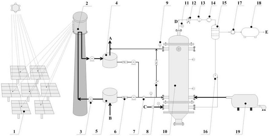
图1是本发明的太阳能驱动的二氧化碳加氢制甲烷的装置示意图;Fig. 1 is the device schematic diagram of the solar-powered carbon dioxide hydrogenation to make methane of the present invention;
图2是本发明的阵列式绝热加氢塔结构示意图;Fig. 2 is the structural representation of the array type adiabatic hydrogenation tower of the present invention;
图3是本发明的加氢反应器列管的横向剖视图;Fig. 3 is the transverse cross-sectional view of the hydrogenation reactor tube of the present invention;
图4是本发明的单根加氢反应器剖面图。Fig. 4 is a sectional view of a single hydrogenation reactor of the present invention.
图中,1-定日镜群,2-高温集热器,3-熔盐泵、4-高温储热塔,5-低温储热塔,6-电磁比例阀,7-流量计,8-旁通阀,9-温度测量变送器,10-阵列式绝热加氢塔,1001不锈钢网堵塞,1002集灰斗,1003熔盐泄出阀1004原料气入口,1005再循环接口,1006烟气入口,1007热熔盐入口,1008列管分布板,1009加氢反应器列管,1010熔盐腔,10011折流板,1012热熔盐出口,1013浮头,1014阵列式绝热加氢塔端盖,1015波纹接管,1016产物气出口,11-压力测量变送器,12-冷凝器,13-水气分离器,14-两级压缩器,15-变压吸附塔,16-气体循环泵,17-压缩器,18-液化塔,19-启动/备用锅炉。In the figure, 1-heliostat group, 2-high temperature collector, 3-molten salt pump, 4-high temperature heat storage tower, 5-low temperature heat storage tower, 6-electromagnetic proportional valve, 7-flow meter, 8- Bypass valve, 9-temperature measuring transmitter, 10-array type adiabatic hydrogenation tower, 1001 stainless steel mesh plug, 1002 ash collecting hopper, 1003 molten salt discharge valve, 1004 raw gas inlet, 1005 recirculation interface, 1006 flue gas Inlet, 1007 hot molten salt inlet, 1008 tube distribution plate, 1009 hydrogenation reactor tube, 1010 molten salt chamber, 10011 baffle, 1012 hot molten salt outlet, 1013 floating head, 1014 array type adiabatic hydrogenation tower end cover , 1015 corrugated pipe, 1016 product gas outlet, 11-pressure measuring transmitter, 12-condenser, 13-water gas separator, 14-two-stage compressor, 15-pressure swing adsorption tower, 16-gas circulating pump, 17- Compressor, 18- Liquefaction tower, 19- Start/standby boiler.
具体实施方式Detailed ways
下面结合附图和具体实施例对本发明作进一步详细说明。The present invention will be further described in detail below with reference to the accompanying drawings and specific embodiments.
如图1所示,本发明的一种太阳能驱动二氧化碳加氢制甲烷的装置,,包括定日镜群1、高温集热器2、熔盐循环泵3高温储热塔4、低温储热塔5、电磁比例阀6、流量计7、旁通阀8、温度测量变送器9、阵列式绝热加氢塔10、变压吸附塔15、液化塔1)和启动/备用锅炉19;As shown in FIG. 1 , a solar-powered device for hydrogenating carbon dioxide to produce methane according to the present invention includes a heliostat group 1, a high-
如图1所示,熔盐泵3、高温储热塔4、低温储热塔5、电磁比例阀6、流量计7、旁通阀8、温度测量变送器9等组成了阵列式绝热加氢塔10的温度控制单元;采用的高温熔融盐二元或者三元硝酸熔盐,包括不同比例混合的KNO3,NaNO3,Ca(NO3)2混合熔盐等。As shown in Figure 1, the
如图1所示,所述阵列式绝热加氢塔10的温度控制方法和步骤如下:As shown in Figure 1, the temperature control method and steps of the array type adiabatic hydrogenation tower 10 are as follows:
a.通过温度测量变送器9分别测量加氢反应器列管1009催化剂床层、熔盐腔1010内、热熔盐入口1007、热熔盐出口1012温度;信号传递至温度控制器;a. The temperature of the
b.通过流量检测器7测量原料气的流速;信号传递至温度控制器;b. The flow rate of the raw gas is measured by the
c.电磁比例阀8接收温度控制器发出信号,分别调节高温热熔盐和低温热熔盐的流量。c. The electromagnetic
d.当加氢反应器列管1009内部温度稳定在工艺设定温度给定误差范围内时,或者在阵列式绝热加氢塔停车时,旁通阀8开启。同时,旁通回路上的电磁比例阀控制旁通回路的熔盐流量。d. When the internal temperature of the
如图1和图2所示,阵列式绝热加氢塔主要部件包括:加氢反应器列管1009、熔盐腔1010、熔盐泄出阀1003、折流板1011、列管分布板1008、浮头1013、波纹管1015、集灰斗1002、阵列式绝热加氢塔上端盖1014。所述的加氢反应器列管1009与阵列式绝热加氢塔10同轴设置,两端分别按通过焊接方式与列管分布板连接;加氢反应器列管1009两端设置了整流层,中间加载有催化剂床层,如图4所示;靠近热熔盐入口1007端的列管分布板采用法兰连接方式与熔盐腔1010壳体固定连接,而靠近热熔盐出口1012端的列管分布板则采用通过法兰与浮头1013连接。浮头1013与阵列式绝热加氢塔上端盖1014联通作为反应产物气的出口通道,中间设置有波纹管1015以抵消加氢反应器列管1009受热或冷却是产生的膨胀和收缩应力。熔盐腔101)内部设置有折流板1011;下部设置有集灰斗1002,和不锈钢网堵塞1001。原料气入口1004和循环气入口1005分别设置在阵列式绝热加氢塔10下部的不同侧。As shown in Figure 1 and Figure 2, the main components of the array type adiabatic hydrogenation tower include:
如图2所示,所述熔盐腔1010内设有多个左右交错布置的折流板1011,形状为为圆形和环形的间隔组合。As shown in FIG. 2 , the
如图2、3所示,加氢反应器列管按多层(本示例中为3层),周向等角度布置。加氢氢反应器列管中整流层,其材料为Al2O3,SiC,SiO2等小球或者颗粒;中间加催化剂床层采用Ni/TiO2、Ni/Al2O3、Ni/CeO2、Ni/SiC、Ni/MgO、Ni/ZrO2、Ni/SBA-15、Ni/MCM-41、Ni/ZSM-5等;催化剂床层位于热熔盐出口法兰和热熔盐入口法兰中心线之间。As shown in Figures 2 and 3, the hydrogenation reactor tubes are arranged in multiple layers (three layers in this example) and are arranged at equal angles in the circumferential direction. The rectifying layer in the tubes of the hydrogenation hydrogenation reactor is made of Al 2 O 3 , SiC, SiO 2 and other small balls or particles; the intermediate catalyst bed is made of Ni/TiO 2 , Ni/Al 2 O 3 , Ni/CeO 2. Ni/SiC, Ni/MgO, Ni/ZrO 2 , Ni/SBA-15, Ni/MCM-41, Ni/ZSM-5, etc.; the catalyst bed is located in the hot molten salt outlet flange and hot molten salt inlet method between the blue centerlines.
如图2所示,浮头1013与阵列式绝热加氢塔上端盖1014中间设置有波纹管1015,以抵消管式加氢反应器加热、膨胀时的位移。As shown in FIG. 2 , a
如图1所示,高温集热器2接收经定日镜群1聚焦后的太阳光,加热由熔盐循环泵3驱动、来至于低温储热塔5的低温热熔盐;再由循环泵驱动进入高温储热塔4。根据加氢反应塔设定的工艺温度和流量,结合温度测量变送器检测到的管式反应器催化剂床层温度、熔盐入口温度和流速、熔盐出口温度,通过调节电磁比例阀6开度,分别调整高温熔盐和低温熔盐的流量,来控制进入到熔盐腔1010内热熔盐的温度和流量,以实现对加氢反应温度的实时、准确控制。从阵列式绝热加氢塔出来的热熔盐和高温储热塔4进入到热力发电系统的热熔盐A汇合,进入太阳能热力发电系统的蒸汽发生系统;而在蒸汽发生系统换热之后的低温热熔盐B循环进入低温储热塔5,再经熔盐泵3送至高温集热器2进行再次加热循环。如图2所示,在阵列式绝热加氢塔10中,热熔盐在熔盐腔1010内、经折流板1011引导,充分加热加氢反应器列管1009至反应工艺温度。CO2与H2的混合气从加氢反应塔入口1005、经集灰斗1002,通过整流层,进入到催化剂床层;反应后产物气D由整流层出,经浮头1013、波纹管1015和阵列式绝热加氢塔端盖1014和下游管道进入到冷凝器12中,在汽水分离器13中脱除水分;然后经两级过压缩,在变压吸附塔15中将产物气D中为反应完全的H2、CO2与CH4分离。得到的CH4经过压缩,再在液化塔18中进行液化得到所需的液化天然气E。变压吸附塔15的残余解吸气,作为原料气由气体循环泵16补充送入到阵列式绝热加氢塔10中。As shown in FIG. 1 , the high-
基于所述的装置进行太阳能驱动的二氧化碳加氢制甲烷的方法,包括以下步骤:A method for solar-driven carbon dioxide hydrogenation to produce methane based on the device, comprising the following steps:
a.太阳能通过定日镜群1,聚焦到高温集热器2;加热在熔盐循环泵3驱动下,从低温储热塔5出来的低温熔盐;被加热后的高温热熔盐被循环泵打入高温储热塔4;a. The solar energy is focused on the
b.高温储热塔4中的部分热熔盐A进入到太阳能热力发电系统中的蒸汽发生器;还有一部分热熔盐进入到阵列式绝热加氢塔10的热力控制系统中;b. Part of the hot molten salt A in the high temperature
c.阵列式绝热加氢塔10开车时,启动启动/备用锅炉,通过燃烧CH4等燃料,将高温烟气导入熔盐腔1010先预热加氢反应器列管1009;在清洗加氢反应器列管1009也采用同样方法,此操作条件下打开下端列管分布板1008上的熔盐泄出阀1003;c. When the array type adiabatic hydrogenation tower 10 is started up, the start-up/standby boiler is started, and the high-temperature flue gas is introduced into the
d.从高温储热塔4出来的高温热熔盐,和从低温储热塔出来的低温热熔盐,分别在电磁比例阀的调节作用下,按照温度控制器给出的控制信号,以一定比例汇合;使加热熔盐以设定温度和流量进入到阵列式绝热加氢塔10中的熔盐腔1010,调节加氢反应器催化剂床层至工艺设定的反应温度200~500℃;换热之后的热熔盐从热熔盐出口1012流出,与热熔盐A汇合进入到太阳能热力发电系统中的蒸汽发生器;d. The high temperature hot molten salt from the high temperature
e.CO2与H2预混合的原料气由原料气入口1004进入阵列式绝热加氢塔10,经列管分布板1008进入加氢反应器列管1009,反应后由波纹管1015进入产物气出口1016管道;e. The feed gas pre-mixed with CO 2 and H 2 enters the array type adiabatic hydrogenation tower 10 from the
f.产物气经过冷凝器12、气液分离器13脱水,再经过压缩14,进入变压吸附塔15;分离得到的CH4被压缩,在液化塔17内液化,得到LNG。变压吸附塔15解吸气主要包含未反应的CO2和H2,经过气体循环泵16再次补充入阵列式绝热加氢塔。f. The product gas is dehydrated through the
本发明不局限于上述具体的实施方式,对于本领域的普通技术人员来说从上述构思出发,不经过创造性的劳动,所作出的种种变换,均落在本发明的保护范围之内。The present invention is not limited to the above-mentioned specific embodiments. For those of ordinary skill in the art, starting from the above-mentioned concept and without creative work, various transformations made all fall within the protection scope of the present invention.
Claims (13)
Priority Applications (1)
| Application Number | Priority Date | Filing Date | Title |
|---|---|---|---|
| CN202010755383.9A CN111908992A (en) | 2020-07-31 | 2020-07-31 | A device and method for producing methane from carbon dioxide driven by solar energy |
Applications Claiming Priority (1)
| Application Number | Priority Date | Filing Date | Title |
|---|---|---|---|
| CN202010755383.9A CN111908992A (en) | 2020-07-31 | 2020-07-31 | A device and method for producing methane from carbon dioxide driven by solar energy |
Publications (1)
| Publication Number | Publication Date |
|---|---|
| CN111908992A true CN111908992A (en) | 2020-11-10 |
Family
ID=73288071
Family Applications (1)
| Application Number | Title | Priority Date | Filing Date |
|---|---|---|---|
| CN202010755383.9A Pending CN111908992A (en) | 2020-07-31 | 2020-07-31 | A device and method for producing methane from carbon dioxide driven by solar energy |
Country Status (1)
| Country | Link |
|---|---|
| CN (1) | CN111908992A (en) |
Cited By (2)
| Publication number | Priority date | Publication date | Assignee | Title |
|---|---|---|---|---|
| CN113416582A (en) * | 2021-08-06 | 2021-09-21 | 宁夏大学 | System for preparing synthesis gas by heating biomass through photo-thermal ceramsite and preparation method thereof |
| CN116716129A (en) * | 2023-07-06 | 2023-09-08 | 太原理工大学 | A solar-driven strake-plate reactor for gasification of carbon-based feedstocks |
Citations (5)
| Publication number | Priority date | Publication date | Assignee | Title |
|---|---|---|---|---|
| US20030006129A1 (en) * | 2001-06-28 | 2003-01-09 | Kazuo Imasaki | Methane/methanol producing system |
| CN102126905A (en) * | 2010-01-15 | 2011-07-20 | 北京长征天民高科技有限公司 | Method and device for preparing liquefied methane by using synthesis ammonia tail gas |
| US20150045458A1 (en) * | 2012-04-24 | 2015-02-12 | Wuhan Kaidi Engineering Technology Research Institute Co., Ltd. | Method and device for converting carbon dioxide in flue gas into natural gas |
| CN105222368A (en) * | 2015-10-30 | 2016-01-06 | 百吉瑞(天津)新能源有限公司 | Based on the solar energy cascade heating high-temperature heat collection system of Molten Salt Heat Transfer accumulation of heat |
| CN108455528A (en) * | 2018-01-15 | 2018-08-28 | 清华大学 | A kind of methane is low-temperature catalyzed to reform the device and method for producing solar energy fuel |
-
2020
- 2020-07-31 CN CN202010755383.9A patent/CN111908992A/en active Pending
Patent Citations (5)
| Publication number | Priority date | Publication date | Assignee | Title |
|---|---|---|---|---|
| US20030006129A1 (en) * | 2001-06-28 | 2003-01-09 | Kazuo Imasaki | Methane/methanol producing system |
| CN102126905A (en) * | 2010-01-15 | 2011-07-20 | 北京长征天民高科技有限公司 | Method and device for preparing liquefied methane by using synthesis ammonia tail gas |
| US20150045458A1 (en) * | 2012-04-24 | 2015-02-12 | Wuhan Kaidi Engineering Technology Research Institute Co., Ltd. | Method and device for converting carbon dioxide in flue gas into natural gas |
| CN105222368A (en) * | 2015-10-30 | 2016-01-06 | 百吉瑞(天津)新能源有限公司 | Based on the solar energy cascade heating high-temperature heat collection system of Molten Salt Heat Transfer accumulation of heat |
| CN108455528A (en) * | 2018-01-15 | 2018-08-28 | 清华大学 | A kind of methane is low-temperature catalyzed to reform the device and method for producing solar energy fuel |
Cited By (2)
| Publication number | Priority date | Publication date | Assignee | Title |
|---|---|---|---|---|
| CN113416582A (en) * | 2021-08-06 | 2021-09-21 | 宁夏大学 | System for preparing synthesis gas by heating biomass through photo-thermal ceramsite and preparation method thereof |
| CN116716129A (en) * | 2023-07-06 | 2023-09-08 | 太原理工大学 | A solar-driven strake-plate reactor for gasification of carbon-based feedstocks |
Similar Documents
| Publication | Publication Date | Title |
|---|---|---|
| CN106762143B (en) | Solar energy chemical recuperation cycle system | |
| CN113090349B (en) | Photothermal coal supercritical water gasification hydrogen cogeneration system and working method | |
| CN102126704B (en) | System and method for producing hydrogen by collecting solar energy in multi-plate mode and coupling biomass supercritical water gasification | |
| CN102444993B (en) | Middle-low temperature solar energy thermochemical energy storage system | |
| CN105508051B (en) | High-temperature gas-cooled reactor helium gas indirect cyclic process hydrogen manufacturing coupled electricity-generation system and method | |
| CN104862010B (en) | A kind of solar energy gasification system based on groove tower combination spot mode | |
| EP4443051A1 (en) | Nitrogen-free combustion and carbon dioxide capture and utilization process for gas-fired boiler | |
| CN114250091B (en) | Biomass gasification unit and artificial natural gas production system | |
| CN104445060B (en) | Comprehensive utilization method for high-temperature energy | |
| CN114540054A (en) | Poly-generation system and method for pyrolyzing biomass by using light-gathering solar energy | |
| CN110357039A (en) | A kind of the synthesis gas preparation system and method for biogas and solar energy complementation | |
| CN111908992A (en) | A device and method for producing methane from carbon dioxide driven by solar energy | |
| CN104456512A (en) | A solar-assisted coal-fired power generation system using CaO to store heat at high temperature and capture CO2 in flue gas | |
| CN109723557B (en) | Oxy-fuel combustion carbon dioxide power generation system with integrated solar methane dry reforming | |
| CN105838450A (en) | Biomass-solar thermal chemical utilization system capable of realizing multi-product output | |
| CN116083125A (en) | Carbon gas co-production system taking carbon dioxide and oxygen as gasifying agents and working method thereof | |
| CN120793960A (en) | Low-temperature low-pressure synthetic ammonia tower and coupling fuel cell renewable flexible synthetic ammonia system | |
| CN120776334A (en) | Wind-solar hydrogen production coupling CO2Polygeneration system and method for trapping and utilizing | |
| CN114163151A (en) | Carbon emission reduction method and system for calcining cement clinker using CO2 storage solar energy | |
| CN119684084A (en) | A method for producing methanol from carbon dioxide by direct combustion of biomass coupled with wind and solar green hydrogen | |
| CN104178234B (en) | Coke-stove gas prepares natural gas and residual-heat utilization method and system with producer gas | |
| CN209586523U (en) | An oxyfuel combustion power generation system integrating solar methane dry reforming | |
| CN117414778A (en) | Flexible carbon storage methanol preparation system and method | |
| CN214032356U (en) | Energy-saving sulfur-tolerant shift system | |
| CN103708417B (en) | A kind of method and device utilizing high-temperature vapor gasified bio-matter hydrogen making |
Legal Events
| Date | Code | Title | Description |
|---|---|---|---|
| PB01 | Publication | ||
| PB01 | Publication | ||
| SE01 | Entry into force of request for substantive examination | ||
| SE01 | Entry into force of request for substantive examination | ||
| RJ01 | Rejection of invention patent application after publication | ||
| RJ01 | Rejection of invention patent application after publication |
Application publication date: 20201110 |