CN1119103C - Display device for displaying goods - Google Patents
Display device for displaying goods Download PDFInfo
- Publication number
- CN1119103C CN1119103C CN99808908A CN99808908A CN1119103C CN 1119103 C CN1119103 C CN 1119103C CN 99808908 A CN99808908 A CN 99808908A CN 99808908 A CN99808908 A CN 99808908A CN 1119103 C CN1119103 C CN 1119103C
- Authority
- CN
- China
- Prior art keywords
- rod
- profiled
- support structure
- support arm
- display device
- Prior art date
- Legal status (The legal status is an assumption and is not a legal conclusion. Google has not performed a legal analysis and makes no representation as to the accuracy of the status listed.)
- Expired - Fee Related
Links
Images







Classifications
-
- A—HUMAN NECESSITIES
- A47—FURNITURE; DOMESTIC ARTICLES OR APPLIANCES; COFFEE MILLS; SPICE MILLS; SUCTION CLEANERS IN GENERAL
- A47F—SPECIAL FURNITURE, FITTINGS, OR ACCESSORIES FOR SHOPS, STOREHOUSES, BARS, RESTAURANTS OR THE LIKE; PAYING COUNTERS
- A47F5/00—Show stands, hangers, or shelves characterised by their constructional features
- A47F5/08—Show stands, hangers, or shelves characterised by their constructional features secured to the wall, ceiling, or the like; Wall-bracket display devices
- A47F5/0807—Display panels, grids or rods used for suspending merchandise or cards supporting articles; Movable brackets therefor
- A47F5/0846—Display panels or rails with elongated channels; Sliders, brackets, shelves, or the like, slidably attached therein
- A47F5/0853—Rail constructions; Brackets
-
- A—HUMAN NECESSITIES
- A47—FURNITURE; DOMESTIC ARTICLES OR APPLIANCES; COFFEE MILLS; SPICE MILLS; SUCTION CLEANERS IN GENERAL
- A47F—SPECIAL FURNITURE, FITTINGS, OR ACCESSORIES FOR SHOPS, STOREHOUSES, BARS, RESTAURANTS OR THE LIKE; PAYING COUNTERS
- A47F5/00—Show stands, hangers, or shelves characterised by their constructional features
- A47F5/08—Show stands, hangers, or shelves characterised by their constructional features secured to the wall, ceiling, or the like; Wall-bracket display devices
- A47F5/0807—Display panels, grids or rods used for suspending merchandise or cards supporting articles; Movable brackets therefor
- A47F5/0815—Panel constructions with apertures for article supports, e.g. hooks
Landscapes
- Display Racks (AREA)
- Mutual Connection Of Rods And Tubes (AREA)
- Vending Machines For Individual Products (AREA)
- Spray Control Apparatus (AREA)
- Chain Conveyers (AREA)
Abstract
Description
本发明涉及商店和展览会上陈列商品用的展示装置。展示装置包括支承结构物,如壁板;至少一根异形杆,它水平地固定在支承结构物上;以及支承臂,它们能装配在此异形杆中。一般说来,展示装置具有若干异形杆,它们有次序、相互间隔地沿水平方向加以布置。支承臂可按需要装配在所有可选择的位置内,并用于直接或间接支承欲展示的商品。典型的用途是用于服装领域,其中悬挂在衣架上的外着服装外衣挂在装配有支承臂的展示装置上。此类展示装置使得所提供的商品能靠近顾客而陈列,销售区域的结构能加以变化,以及装修的改变不复杂。更有甚者,所提供的商品能以仔细的次序加以展示,从而在所有时间内占优势的总体印象总是有利于销售。The invention relates to a display device for displaying goods in shops and exhibitions. The display device comprises a support structure, such as a wall panel; at least one profiled bar, which is fixed horizontally on the support structure; and support arms, which can be fitted in the profiled bar. Generally speaking, the display device has several special-shaped rods, which are arranged in order and spaced apart from each other along the horizontal direction. The support arms can be assembled in all alternative positions as desired and are used to directly or indirectly support the merchandise to be displayed. A typical use is in the field of clothing where outerwear garments hung on hangers are hung on a display fitted with support arms. Such display devices allow the offered goods to be displayed close to customers, the structure of the sales area to be varied, and the decoration to be changed uncomplicated. What's more, the offered merchandise can be presented in a careful sequence so that the overall impression prevailing at all times is always favorable to sales.
提及的普通类型的展示装置已在在前技术中多次加以披露。GB-A-2241426披露了一种展示壁,它具有水平的直线插入窄缝,该窄缝倾斜地向下伸入后壁。设置了形状为数字“1”的钩子,以便装配进入这些窄缝中,在这些钩子上固定地布置了伸入于房间中的支承臂。大部分窄缝表面仍未被占据。可随意地看到,这在视觉上是不利的。此外,在单根支承臂上只能有低的负载,以避免它的脱落。CH-A-650137和DE-A-3428759提出的装置也以后壁为基础,后壁具有水平凹槽,于其中可插入钩子。Display devices of the general type mentioned have been disclosed several times in the prior art. GB-A-2241426 discloses a display wall having a horizontal rectilinear insertion slot which projects obliquely downwards into the rear wall. Hooks in the shape of the number "1" are provided to fit into these slits, on which hooks are fixedly arranged support arms protruding into the room. Most of the slot surface remains unoccupied. It can be seen at will, which is visually disadvantageous. Furthermore, only low loads can be placed on the individual support arms in order to avoid their falling out. The devices proposed by CH-A-650137 and DE-A-3428759 are also based on a rear wall having horizontal grooves into which hooks can be inserted.
GB-A-2206033和GB-A-2222070披露了具有椭圆形异形杆的展示装置,具有支架零件的支承臂可放置于异形杆上。异形杆和支架零件是较笨重的部件,因此,这些装置不符合所有美学要求。GB-A-2206033 and GB-A-2222070 disclose display devices with elliptical profiled bars on which support arms with bracket parts can be placed. The profiled rod and bracket parts are the bulkier components and as such, these units do not meet all aesthetic requirements.
FR-A-2611468提出一种装置,它具有异形零件和支承臂,异形零件在顶部具有钩形边缘,而支承臂具有钢丝圈,钢丝圈装配在钩形边缘中。这样,支承臂不能装配在每一需要的位置上,边缘和圈看起来十分特殊。FR-A-2611468 proposes a device having a profiled part with a hook edge at the top and a support arm with a traveler fitted in the hook edge. Thus, the support arm cannot be fitted in every desired position, and the edges and rings look very peculiar.
WO-A-9114388包括具有不同异形轨道和支承臂的展示装置的各种改型。这时,或应用复杂、粗糙的形状和较复杂的支承臂,或绝大部分的窄缝表面未被占据,它们从外部可看到。WO-A-9114388 includes various modifications of displays with different profiled rails and support arms. In this case, either complex, rough shapes and more complex support arms are used, or most of the slit surfaces are left unoccupied and they are visible from the outside.
由于直到目前为止的现存展示装置的不完善性和有限的使用可能性,本发明的目的是提出改进的展示装置,它允许有很大的可变性,具有牢固的支承能力,能迅速改变设备的周围,安全地支承商品,甚至在买卖兴旺的时候,以及能符合变化多样的美学要求。所使用的异形杆有最可能简单的横截面,而支承臂也具有不复杂的结构,从而整个装置能便宜地生产,并能以灵活的方式进行改变。如果异形杆的宽度是支承臂宽度的若干倍,则后者能装配在沿异形杆的任何要求的水平位置-即以可完全自由选择的方式,或在一个格板之内-然后加以紧固安装。在一个设计方案中,异形杆设计成短的片段,以便能在壁板上成行成列地布置成栅格形状。需避免的一件事是[空缺],没有用已装配的支承臂加以安装的异形杆敞开,可看见不规则的窄缝截面。Due to the imperfections and limited possibilities of use of the existing display devices until now, the object of the present invention is to propose an improved display device, which allows a great variability, has a firm support capacity, and can quickly change the configuration of the equipment. around, securely support merchandise, even when business is booming, and can meet varied aesthetic requirements. The profiled rods used have the simplest possible cross-section, and the support arms also have an uncomplicated construction, so that the entire arrangement can be produced cheaply and can be changed in a flexible manner. If the width of the profiled bar is several times the width of the support arm, the latter can be fitted at any desired horizontal position along the profiled bar - i.e. in a completely freely selectable manner, or within a grid - and then fastened Install. In one refinement, the profiled rods are designed as short segments in order to be able to arrange them in a grid-like arrangement in rows and columns on the wall. One thing to avoid is [vacancy], profiled rods that are not mounted with an assembled support arm open to see irregular narrow slit sections.
展示装置至少具有一根细长的轨道形、杆形或管形的异形杆,该异形杆至少基本水平地紧固在支承结构物上;以及支承臂,它能装配在异形杆上。在支承臂的杆部分的一端垂直或倾斜地连接有插入板,该插入板突出于杆部分的上侧之上,并具有倾斜边缘,该边缘沿杆部分的轴向指向,并能被中央缺口分裂成两个舌状物。支承臂装配在异形杆上的步骤是,相对水平抬高杆部分的自由端,从异形杆的下方将倾斜边缘纳入异形杆,并在装配之后,将自由端降低至端部位置。在装配的端部位置,插入板的平面部分支承在支承结构物的前侧上,而倾斜边缘倚靠在异形杆上的倾斜表面上,或插入至凹槽中,或啮合在异形杆之后,并部分越过异形杆。为异形杆已发展了6个不同的实施例。The display device has at least one elongated rail-shaped, rod-shaped or tubular profiled bar fastened at least substantially horizontally to the support structure and a support arm which can be fitted on the profiled bar. Attached vertically or obliquely to one end of the rod part of the support arm is an insert plate which protrudes above the upper side of the rod part and has an inclined edge which is directed in the axial direction of the rod part and can be covered by a central notch Split into two tongues. The mounting of the support arm on the profiled rod involves raising the free end of the rod part relative to the horizontal, incorporating the beveled edge into the profiled rod from below the profiled rod and, after assembly, lowering the free end into the end position. In the assembled end position, the flat part of the insert plate bears on the front side of the supporting structure, while the inclined edge rests on the inclined surface on the profiled rod, or is inserted into a groove, or engages behind the profiled rod, and part over the profiled rod. Six different embodiments have been developed for profiled rods.
异形杆或至少近似地伸展在壁板的整个宽度之上,从而按选择定位的一根或多根支承臂能沿着各根异形杆而装配。在一个设计方案中,异形杆设计成短片段,在其中只能装配一根支承臂。为将壁板竖立在房中-壁板可从两个侧表面加以接近-这两面壁板表面可装配有异形杆和/或异形杆片段。这时,在各种情况下,相互相对位于侧表面两侧的异形杆和/或异形杆片段最好通过壁板相互连接。The profiled bars extend, or at least approximately, over the entire width of the panel, so that one or more selectively positioned support arms can be fitted along each profiled bar. In one refinement, the profile rod is designed as a short section, into which only one support arm can be fitted. In order to erect the wall panel in the room - the wall panel can be accessed from two side surfaces - these two wall panel surfaces can be equipped with profiled rods and/or profiled rod segments. In each case, the profiled rods and/or the profiled rod segments lying opposite each other on the side surfaces are preferably connected to one another by means of wall panels.
合适的支承臂是商店建设中所有已知类型的支承臂,即首先是具有以弯曲或成角度方式水平伸展的支柱的支承臂。有一种支承臂,此支承臂具有中央支柱,在其上布置着插入板以便装配在异形杆中,从此支承臂可射出若干成岔开分支形的另一些支柱。相对位于插入板上的两根支承杆的端部之间可固定地安置一根横向杆,该横向杆在装配状态平行于支承结构物而延伸。于是横向杆可直接作为商品托架,在其上例如能悬挂挂有服装的衣架,而支承杆具有撑架的作用。搁板可固定在两根或多根支承杆上-它们同样起撑架的作用。由于有如此众多类型的支承杆,就可能将若干支承杆装配在异形杆上,支承杆它们自身,或固定于其上的直接商品托架,则延伸于若干水平平面中。此类布置的一个实例是横向杆固定于两根支承杆之间,而设置于其上的搁板由另两根支承杆加以支承。Suitable support arms are support arms of all types known in shop construction, ie above all support arms with struts running horizontally in a curved or angled manner. There is a support arm with a central support on which an insert plate is arranged for fitting in a profiled rod, from which several further supports in the form of branching branches can be projected. Between the ends of the two supporting rods oppositely located on the insert plate, a transverse rod can be fixedly arranged, which in the assembled state extends parallel to the supporting structure. The transverse bar can then directly serve as a shelf for goods on which, for example, clothes hangers can be hung, while the supporting bar has the effect of a brace. The shelf can be fastened to two or more support rods - which also function as braces. Since there are so many types of support rods, it is possible to fit several support rods on profiled rods, the support rods themselves, or the immediate merchandise carriers fixed thereto, then extending in several horizontal planes. An example of such an arrangement is where a transverse bar is fixed between two support bars and a shelf disposed thereon is supported by the other two support bars.
·第一实施例·First embodiment
异形杆由圆形杆构成,它与之间隔一个距离,水平地放置在,最好拧在支承结构物-例如壁板表面上。垫片套筒放置在紧固螺栓上,用于将圆形杆与支承结构物的前侧相隔开。插入板上成圆形的倾斜边缘能插入于圆形杆与支承结构物的表面之间,如果杆部分的自由端相对水平而抬高。倾斜边缘插入后,支承臂被放至水平位置,这样,倾斜边缘啮合于异形杆之后,并部分位于其上。同时,位于倾斜边缘之下的支承板的平面部分被支承在支承结构物的前侧上。·第二实施例The profiled rods consist of circular rods which are spaced apart and placed horizontally, preferably screwed, onto the surface of the supporting structure, for example a wall panel. Spacer sleeves are placed over the fastening bolts to space the round rod from the front side of the supporting structure. The rounded bevelled edge of the insert plate can be inserted between the round rod and the surface of the supporting structure if the free end of the rod part is raised relative to the horizontal. After the beveled edge has been inserted, the support arm is brought into a horizontal position so that the beveled edge engages behind and partially rests on the profiled rod. At the same time, the planar portion of the support plate located below the inclined edge is supported on the front side of the support structure. ·Second embodiment
异形杆是椭圆横截面的直线片段,它与之间隔一个距离、水平地拧在支承结构物上。轴向连续或片段的插入凹槽沿异形杆的面向支承结构物的表面而伸展。插入板上倾斜边缘的最前部分能插入于插入凹槽中,如果杆部分的自由端相对水平抬高的话。倾斜边缘被插入后,整个支承臂重又被放入水平位置,这样,插入板的平面部分支承在支承结构物的前侧上。作为一种选择,倾斜边缘具有缺口,该缺口伸入至平面部分,从而可能将支承臂装配在异形杆与支承结构物之间,甚至在螺丝连接区域中,于是,紧固螺栓与垫片套筒或其它加厚部分一起位于缺口中。·第三实施例Profiled rods are rectilinear segments of elliptical cross-section screwed horizontally to the supporting structure at a distance therebetween. The axially continuous or segmented insertion grooves run along the surface of the profiled rod facing the support structure. The foremost part of the inclined edge on the insertion plate can be inserted into the insertion groove if the free end of the rod part is raised relative to the horizontal. After the beveled edge has been inserted, the entire support arm is again brought into a horizontal position, so that the planar part of the insert plate bears on the front side of the support structure. As an option, the slanted edge has a notch, which protrudes into the plane part, so that it is possible to fit the support arm between the profiled bar and the support structure, even in the area of the screw connection, so that the fastening bolt and the washer sleeve The barrel or other thickened portion is located in the notch together. · The third embodiment
替代第二实施例中的插入凹槽,在面向支承结构物前侧的这一侧,异形杆具有纵向倾斜表面,在其上安置了插入板的倾斜边缘,如果支承臂已装配的话。倾斜表面朝着杆部分方向及在其上升角下上升,与倾斜边缘的角相互补。·第四实施例Instead of the insertion groove in the second embodiment, on the side facing the front side of the support structure, the profiled bar has a longitudinally inclined surface on which the inclined edge of the insertion plate is seated, if the support arm is assembled. The sloped surface rises towards the stem portion and at its rising angle, complementary to the angle of the sloped edge. · Fourth embodiment
异形杆是T-截面的,T-截面的底分枝水平地放置在支承结构物上,或者,侧向插入至水平地包含在支承结构物中的T-凹槽中,结果,异形杆的中央分枝的自由部分从支承结构物的前侧伸入房中。中央分枝具有规则的窄缝栅格,该窄缝栅格甚至在异形杆插入于其中时仍是可接近的。插入板上的倾斜边缘能通过任何所选的窄缝插入窄缝栅格,如果支承臂的杆部分的自由端相对水平抬高的话。倾斜边缘通过所选的窄缝插入后,整条支承臂被放回至水平位置,这样,倾斜边缘倚靠在中央分枝的上侧,而插入板的平面部分支承在支承结构物的前侧上。·第五实施例The profiled bar is of T-section, the bottom branch of the T-section is placed horizontally on the supporting structure, or inserted laterally into a T-groove contained horizontally in the supporting structure, as a result, the profiled bar's The free part of the central branch protrudes into the room from the front side of the supporting structure. The central branches have a regular grid of slits that are accessible even when the profiled rod is inserted therein. The beveled edge on the insert plate can be inserted into the slot grid through any selected slot if the free ends of the rod parts of the support arms are raised relative to the horizontal. After the beveled edge has been inserted through the selected slit, the entire support arm is brought back to a horizontal position so that the beveled edge rests on the upper side of the central branch and the flat part of the insert plate rests on the front side of the support structure . · Fifth embodiment
替代第四实施例的窄缝栅格,异形杆在中央分枝的下侧具有纵向凹槽,该纵向凹槽朝着自由外边缘倾斜地上升,插入板的倾斜边缘穿透进入纵向凹槽中,如果支承臂被装配的话。凹槽的上升角与倾斜边缘的上升角相互补。在 第一子修改方案中,异形杆在支承结构物中只插入至如此的深度,以及凹槽的进入口以如此的方式进行定位和选定尺度,以致进入口在异形杆的整个长度上可接近,即支承臂能装配在沿异形杆的任何位置上。Instead of the slit grid of the fourth embodiment, the profiled bar has a longitudinal groove on the underside of the central branch, which rises obliquely towards the free outer edge, into which the oblique edge of the insert plate penetrates , if the support arm is assembled. The rise angle of the groove is complementary to the rise angle of the beveled edge. In a first sub-modification , the profiled rod is inserted in the supporting structure only to such a depth, and the entry opening of the groove is positioned and dimensioned in such a way that the entry opening is accessible over the entire length of the profiled rod. Access, ie the support arm can be assembled anywhere along the profiled rod.
在 第二子修改方案中,当异形杆插入支承结构物中时,凹槽的进入口封闭。围绕凹槽下侧的截面使其足以高达支承结构物的表面。这样,进入口就隐蔽地位于支承结构物中的T-凹槽内,异形杆插入于其中。为设置具有一定装配位置的栅格,异形杆的中央分枝的下侧的截面设置有间隙,其结果是,进入口在间隙区域加宽,支承臂只能装配于此处。·第六实施例In a second sub-modification , the access opening of the groove is closed when the profiled rod is inserted into the support structure. The section around the underside of the groove is such that it is sufficiently high up to the surface of the supporting structure. In this way, the access opening is concealed within a T-groove in the support structure, into which the profiled rod is inserted. To provide a grid with a certain assembly position, the section of the underside of the central branch of the profiled bar is provided with a gap, with the result that the access opening is widened in the region of the gap, where the support arm can only be fitted. · The sixth embodiment
具有矩形或方形横截面的该异形杆作为整体被其后固定边缘放置在支承结构物上。紧固最好通过螺纹拧紧实现。凹槽开始于固定边缘,轴向沿异形杆延伸,并朝着外边缘的方向倾斜地上升。支承臂的装配位置在栅格内是隔开的,这些装配位置由在支承臂的插入板的宽度之上、规则地设置于异形杆下侧上的截面中的间隙形成。相应的支承臂只能装配在于间隙位置上放置在支承结构物上的异形杆中。在间隙的外侧,截面围绕凹槽的下侧,该截面至少实际上无间隙地放置在支承结构物上。·第七实施例The profiled bar, having a rectangular or square cross-section, is placed as a whole by its rear fixing edge on the support structure. Fastening is preferably achieved by screwing. The groove starts at the fixed edge, extends axially along the profiled rod, and rises obliquely towards the outer edge. The fitting positions of the support arms are spaced apart within the grid, these fitting positions being formed by gaps in the section regularly arranged on the underside of the profiled rod over the width of the insert plate of the support arms. Corresponding support arms can only be fitted in profiled bars which are placed on the support structure in a gap position. On the outside of the gap, the section surrounds the underside of the groove, which section rests on the support structure at least virtually without gap. · Seventh embodiment
此异形杆相似于第五实施例。异形杆的中央分枝的前边缘在此处也从支承结构物突出,而用于装配支承臂的凹槽可自下方接近。异形杆插入于两块在它们纵向边缘具有凹槽的壁板之间,异形杆的垂直底分枝啮合在这些凹槽中,好似它是连接舌状物。异形杆的背部分重叠两块壁板,并位于支承结构物的后侧上。背部分用于支承连接在一起的壁板,并最终用于直接紧固在墙上,或与垂直的副撑架相连接。沿支承结构物延伸的窄缝栅格设置在中央分枝从支承结构物向前突出的截面上,这样-作为从下方可插入的支承臂的补充-附加的可插入支架臂可自上方装配在异形杆中。This profiled rod is similar to the fifth embodiment. Here too, the front edge of the central branch of the profiled rod protrudes from the support structure, while the recess for fitting the support arm is accessible from below. The profiled rod is inserted between two wall panels having grooves at their longitudinal edges, the vertical bottom branches of the profiled rod engaging in these grooves as if it were a connecting tongue. The back portion of the profiled bar overlaps the two wall panels and is located on the rear side of the supporting structure. The back part is used to support the wall panels connected together, and is finally used to fasten directly to the wall, or to connect with vertical sub-braces. A grid of slits extending along the supporting structure is provided on the section where the central branch protrudes forward from the supporting structure, so that - in addition to the supporting arms insertable from below - additional insertable support arms can be fitted from above on the Shaped rod.
附图表示如下:Accompanying drawing expresses as follows:
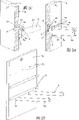
图1A-示意地展示了壁板片段,该壁板片段具有安置在其上的异形杆,而支架臂装配在异形杆上;Figure 1A - schematically shows a panel segment with a profiled rod mounted thereon on which the bracket arms are fitted;
图1B-示意地展示了具有插入的异形杆的壁板片段,而支架臂装配在异形杆上;Figure 1B - schematically shows a panel segment with inserted profiled rods on which the bracket arms are assembled;
图2A-展示装置的第一实施例的局部截面,该展示装置具有形为圆形杆,并放置在支承结构物上的异形杆;Figure 2A - Partial cross-section of a first embodiment of a display device having a profiled rod in the shape of a circular rod placed on a support structure;
图2B-展示装置的第二实施例的局部截面,该展示装置具有异形杆,异形杆安置在支承结构物上,并具有轴向插入凹槽;Fig. 2B - Partial cross-section of a second embodiment of a display device with profiled rods placed on a support structure with axial insertion grooves;
图2C-展示装置的第三实施例的局部截面,该展示装置具有异形杆,异形杆安置在支承结构物上,并具有轴向凹槽型线;Figure 2C - Partial cross-section of a third embodiment of a display device having a profiled rod placed on a support structure and having an axial groove profile;
图2D-墙片段的透视图,该墙片段具有图2C的第三实施例的展示装置;Figure 2D - Perspective view of a wall segment with the display device of the third embodiment of Figure 2C;
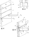
图3A-展示装置的第四实施例的局部截面,该展示装置具有形为T-截面的异形杆,它插入在支承结构物中,并具有轴向窄缝栅格;Fig. 3A - Partial cross-section of a fourth embodiment of a display device with profiled rods in the shape of a T-section inserted in a supporting structure with a grid of axial slits;
图3B-作为第五实施例的第一子修改方案中的展示装置的局部截面,该展示装置具有形为T-截面的异形杆,它插入在支承结构物中,并具有轴向插入凹槽;Figure 3B - Partial section of a display device as a first sub-modification of the fifth embodiment, with a profiled bar in the shape of a T-section, which is inserted in a support structure and has an axial insertion groove ;
图3C-墙片段的透视图,该墙片段具有图3B的第五实施例的展示装置;Figure 3C - Perspective view of a wall segment with the display device of the fifth embodiment of Figure 3B;
图4A-示意地展示了支承臂,该支承臂具有杆部分及放置在其前侧的插入板;Figure 4A - schematically shows a support arm with a rod portion and an insert plate placed on its front side;
图4B-图4A中插入板的两种透视图;Figure 4B—two perspective views of the insert board in Figure 4A;
图5A-图2C中第三实施例的整根异形杆的透视图;The perspective view of the whole special-shaped rod of the third embodiment in Fig. 5A-Fig. 2C;
图5B-图2C和5A中异形杆的垂直横截面;Figure 5B—vertical cross-section of the shaped rod in Figures 2C and 5A;
图5C-图5A的异形杆的透视图,异形杆与支承臂相啮合;5C-Perspective views of the profiled rod of FIG. 5A, the profiled rod engaged with the support arm;
图6A-图3B中第五实施例的第一子修改方案的整根异形杆的透视图;The perspective view of the whole special-shaped rod of the first sub-modification of the fifth embodiment in Fig. 6A-Fig. 3B;
图6B-图3B和6A中异形杆的垂直横截面;Figure 6B—a vertical cross-section of the shaped rod in Figures 3B and 6A;
图7A-取自图3B中位于异形杆最大插入深度时的X的详示图;Figure 7A - a detailed view of X taken from Figure 3B at the maximum insertion depth of the profiled rod;
图7B-取自图3B中位于异形杆最小插入深度时的X的详示图;Figure 7B - a detailed view of X taken from Figure 3B at the minimum insertion depth of the profiled rod;
图8A-壁板的示意展示,该壁板具有成行成列放置于其上的短异形杆片段,支架臂装配在两段异形杆片段上;Figure 8A - Schematic representation of a wall panel having short profiled rod segments placed on it in rows and columns, with bracket arms assembled on two profiled rod segments;
图8B-异形杆的透视图,该异形杆具有装配的支架臂;Figure 8B - Perspective view of a profiled rod with assembled bracket arms;
图9A-壁板的角,它具有布置在壁板两侧上的异形杆片段;Figure 9A - Corner of a panel with profiled rod segments arranged on both sides of the panel;
图9B-图9A中的壁板角的分解图,壁板角具有异形杆片段;Figure 9B - an exploded view of the wall panel corner in Figure 9A with profiled rod segments;
图9C-图9A中壁板角的透明展示图,壁板角具有装配的异形杆片段;Figure 9C - a transparent representation of the corner of the siding in Figure 9A with the assembled profiled rod segments;
图10-异形杆具有装配的支承臂,这些支承臂伸展于两个一个位于另一个之上的平面中;Figure 10 - Profiled bars with assembled support arms extending in two planes one above the other;
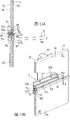
图11A-作为图3B和6A中第五实施例的第二子修改方案的整根异形杆的透视图,该异形杆具有在中央分枝的下侧上的规则的间隙;Figure 11A - a perspective view of a whole profiled rod as a second sub-modification of the fifth embodiment in Figures 3B and 6A, with regular gaps on the underside of the central branch;
图11B-取自图11C中Y的详示图;Figure 11B - Detailed view taken from Y in Figure 11C;
图11C-图11A中的异形杆,该异形杆插入在支承结构物中,并具有装配的支承臂;Fig. 11C - the profiled rod in Fig. 11A, which is inserted in the support structure and has the support arm assembled;
图12A-第六实施例的整根异形杆的透视图;The perspective view of the whole special-shaped rod of Fig. 12A-the sixth embodiment;
图12B-取自图12C中Z的详示图;Figure 12B - a detailed view taken from Z in Figure 12C;
图12C-图12A中的异形杆,该异形杆插入在支承结构物中,并具有装配的支承臂;Fig. 12C - the profiled rod in Fig. 12A, which is inserted in the support structure and has the support arm assembled;
图13A-第七实施例的异形杆的局部垂直截面图,异形杆位于壁板内,并装配有支承臂;Figure 13A - Partial vertical cross-sectional view of a seventh embodiment of a shaped rod located within a wall panel and fitted with a support arm;
图13B-图13A的异形杆的局部透视图,异形杆位于壁板内,在壁板的后侧具有竖直的副撑架;Fig. 13B - partial perspective view of the shaped rod of Fig. 13A, the shaped rod is located in the wall panel, with a vertical sub-bracket on the rear side of the wall panel;
图13C-图13A的异形杆的局部透视图,异形杆位于壁板内,并具有支架臂;Figure 13C-Partial perspective view of the shaped rod of Figure 13A, the shaped rod is located in the wall panel and has a bracket arm;
图13D-图13C的局部垂直截面,它具有支架臂;Figure 13D - a partial vertical section of Figure 13C, which has a stand arm;
图13E-图13C的局部垂直截面,它具有装配的支承臂及附加的支架臂;而Figure 13E - a partial vertical section of Figure 13C with the assembled support arms and additional support arms; and
图13F-整块壁板的透视图,壁板具有若干如图13A的异形杆,在支承结构物的后侧具有副撑架。Figure 13F - Perspective view of a monolithic wall panel with several profiled bars as in Figure 13A, with secondary braces on the rear side of the supporting structure.
本发明提出的展示装置的样板实施例的详细说明将结合附图在下文中给出,最后将提出可能的修改。图1A A detailed description of a sample embodiment of the display device proposed by the invention will be given below with reference to the accompanying drawings, and possible modifications will be suggested at the end. Figure 1A
异形杆1、2、3沿水平方向,按次序并相互平行间隔地放置在支承结构物9上,首先是壁板片段上。异形杆1、2、3计划用于安装支承臂8。这时,为举例起见,杆部分80突出在房间中的两根支承臂8装配在布置于中心高度的异形杆1、2、3上。所设置的杆部分80用于直接或间接地安装需展现的商品,例如,用于悬挂挂在衣架上的服装物品。通常在商店和商品展销会的建筑中,壁板片段具有一定的框格尺寸,这样,若干壁板片段能相互连接,形成一面壁面。The special-shaped
以下说明适用于说明书的所有余下部分。如果图中所含的标号是为了明确这一目的,而不是为了在说明书紧随的有关文本中加以解释,则标号按照在图的先前或随后的说明书中提及的位置中的标号加以标出。为清楚起见,在稍后的图中,部件的重复标记大部分加以避免,只要在附图中能明确地看出,这些部件是“再现的”部件。图1B The following instructions apply to all remaining parts of the manual. If a reference number is included in a figure for this purpose and not for interpretation in the relevant text immediately following the specification, the reference number is indicated in the same position as the reference number in the previous or subsequent description of the figure . For the sake of clarity, in the later figures, the repeated labeling of parts is mostly avoided, as long as it can be clearly seen in the drawings that these parts are "reproduced" parts. Figure 1B
该图的展示装置基本相当于图1A的展示装置,只是异形杆4、5的结构及它们的固定方法不同。沿水平方向,有次序并相互平行间隔地布置的异形杆4、5插入在支承结构物9中-这里,它们又是壁板片段。异形杆4、5也还是计划用于安装支承臂8,它们突出在房间中的杆部分80用于安装欲展示的商品。图2A The display device of this figure is substantially equivalent to the display device of Fig. 1A, except that the structures of special-shaped
在展示装置的第一实施例中,放置在支承结构物9的前侧90上的异形杆1具有圆形横截面。若干螺栓10位于一个平面中,并通过呈现于支承结构物9中的通孔91,于异形杆1的纵向轴线的垂直方向突出伸展。外螺纹12最好设置在自由螺栓端11上,这样,螺母(未表示)能从支承结构物9的后侧92拧在突出的直通螺栓端11上,以便紧固异形杆1。布置在自由螺栓端11的相对侧的是加厚部分13,它形成一个面向自由螺栓端11的环形台肩14。加厚部分13可通过螺栓10的相应设计加以生产,或由推压在螺栓10上的垫片套筒形成。台肩14具有比通孔91大的外径,因此,放置在支承结构物9的前侧90上,这样,异形杆1就被固定,并具有一个相对前侧90的间隙S。In a first embodiment of the display device, the profiled
支承臂8具有插入板81,该插入板81垂直地连接至杆部分80的前侧,因此,支承臂8既能装配在两根螺栓10之间的异形杆1上,也能围绕螺栓10而安装。围绕螺栓10-逻辑上讲是位于加厚部分13的区域-此围绕之所以可能,是由于有了缺口82,该缺口82呈现于插入板81中,并从插入板81的上边缘85中心地向下延伸。两个舌状物83向着杆部分80的方向弯曲,与异形杆1的外圆部分互补,并形成于缺口82的两侧。插入板81至少向上突出在已安置的杆部分80的外径之上,这样,在装配状态,异形杆1不会与杆部分80相碰撞。插入板81可谓是位于间隙S内,这时两个舌状物83啮合于异形杆1之后,并支承在圆形横截面异形杆1的上侧15上。支承臂8的安装只有在杆部分80的自由端相对水平方向抬高时才可能;只有在此情况下,弯曲的舌状物83能通过间隙S。舌状物83插入后,支承臂8重又置于水平位置。支承在异形杆1的上侧15上的舌状物83阻止已装配的支承臂8下落。如要卸去支承臂8,杆部分80的自由端必须预先抬高。支承臂8的固有重量引起与异形杆1接触的那些舌状物83的表面压靠在异形杆1上。同时,位于舌状物83之下的插入板81的平面部分84支承在支承结构物9的前侧90上。随着支承臂8上的负荷增加,舌状物83在异形杆1的按压增加,同时,平面部分84在前侧90上的按压,根据杠杆原理得到加强。图2B The
第二实施例与前一图的不同只在于异形杆2的横截面,在其中设置有插入凹槽20;舌状物83的弯曲以及舌状物83在插入凹槽20中的啮合。异形杆2具有基本为椭圆形的横截面,但这只是圆形杆1的一种替代方案,用其它方式也不重要。异形杆2也可具有圆形横截面。本质性的特点是轴向插入凹槽20,它面向前侧90、沿着异形杆2而延伸,并水平地伸展进入异形杆2。插入板81中的缺口82的深度较小,舌状物83朝着杆部分弯曲的弯曲半径也小一些。这时,舌状物83基本在直角下向外弯曲,从而舌状物83的逐渐变细的部分具有水平取向。The second embodiment differs from the previous figure only in the cross-section of the profiled rod 2 in which the insertion groove 20 is arranged; the bending of the
在装配状态,插入板81还是位于间隙S中,螺栓10的加厚部分13最终位于缺口82中,而舌状物83的水平逐渐变细的部分安置于插入凹槽20中。这时,杆部件80的自由端也必须抬高,以便能将插入板81的,固定地以一端布置在杆部分80上的舌状物83插入至插入凹槽20中。插入板81的平面部分84由于支承臂8的固有重量而压靠着支承结构物9的前侧90,并在支承臂8被加载时受到加强,同时,舌状物83更加牢固地安置于插入凹槽20中。支承臂8的拆除按相反方向进行,从而杆部分80的自由端首先必须抬高,以便舌状物83与插入凹槽20脱开。此后,舌状物83能从间隙S中拉出,支承臂被卸下。图2C、2D和4A至5C In the assembled state, the
第三实施例也具有不同横截面轮廓线的异形杆3以及不同弯曲的舌状物83。异形杆3的横截面大致为椭圆形,并在面向支承结构物9的前侧90的侧边至少具有一个倾斜表面30,该倾斜表面30沿异形杆3轴线纵向地伸展,并从异形杆3的下半部向着异形杆3的水平中心轴线M在螺距角α下上升。最好设置又一倾斜表面31,此表面从异形杆3的上半部向着异形杆3的水平中心轴线M在螺距角α下下降。为装配支承臂8只要求有下倾斜表面30。倾斜表面30、31的对称布置使其可能将转过180°的异形杆3安置在支承结构物9的前侧90上,这样,早先位于顶部的倾斜表面31就位于底部。这简化了组装,因为当具有对称布置的螺栓10时,对异形杆3已转动的位置不须加以注意。The third embodiment also has a profiled
在插入板81缺口82两侧的舌状物83朝杆部分80的方向弯曲,与螺距角α成互补形式,舌状物83的高度对应倾斜表面30、31的宽度。在装配状态,螺栓10的加厚部分13位于缺82内,而插入板81位于间隙S中,即倾斜的舌状物83啮合于异形杆3之后,并倚靠在倾斜表面30或31上,该倾斜表面30或31在每种情况均位于底部。若干有次序地进行分布的螺栓10能插入至互补的通孔91中,以便坚实地紧固异形杆3。支承臂8还能装配在螺栓10之外;在这类布置中,缺82保持未占用状态。支承臂8最好装配在螺栓10的区域,特别当它们装有重负载时,因为装置在该点具有最好的支承能力。如对前述实施例已说明的一样,在装配和卸除支承臂8时,也要求抬高杆部分80的自由端。图3A The
现在介绍的第四实施例与截止目前处理的实施例有明确的差异。异形杆4具有T-横截面,它具有底分枝43和中央分枝44,中央分枝44沿中心并垂直地位于底分枝43上。窄缝栅格40沿中央分枝44延伸,并具有系统成行布置的窄缝42,窄缝栅格40设置在中央分枝44的自由外边缘的附近。为将异形杆4固定在支承结构物9上,由垂直截面94和呈现在前侧90上的水平截面95构成的T-凹槽93被包含于所述支承结构物中。垂直截面94用于安放异形杆4的底分枝43,而中央分枝44位于水平截面95中,中央分枝44从前侧90向外突出,这样,与前侧90相隔距离为间隙S的窄缝栅格40就可接近以便将插入板81的舌状物83安装在任何要求的窄缝42中。The fourth embodiment now presented has definite differences from the embodiments dealt with so far. The profiled rod 4 has a T-cross section with a
设置两个舌状物83可能是明智的,该舌状物83由位于它们之间的缺口82产生,因为这样还能应用图2B提出的装置中的支承臂8。不然,在第四实施例中不要求在插入板81中有缺82,因为此处没有螺栓10需围绕。舌状物83的弯曲与图2A提出的设计相同。在装配状态,舌状物83按支承臂8的所选的位置,通过窄缝42,支承在中央分枝44的上侧45上,向着其外边缘突出。这里,支承臂8的装配和卸除没有任何替换方法,也要求抬高杆部分80的自由端。如所有先前实施例的情况一样,在装配状态,插入板81的平面部分84支承在支承结构物9的前侧90上。T-凹槽93最好由铣削制成,而异形杆4则通过侧向推压插入T一凹槽93中。图3B、3C和6A It may be advisable to provide two
展示装置的第五实施例同样以具有T形横截面的异形杆5作为基础,T形横截面具有底分枝53和沿中心并垂直地位于底分枝53上的中央分枝54。底分枝53又是嵌入在T-凹槽93的垂直截面94中,而中央分枝54位于所述凹槽的水平截面95中,且中央分枝54从支承结构物9的前侧90伸出。中央分枝54的下侧56设置有凹槽50,该凹槽50向着中央分枝54的自由外边缘方向倾斜地上升,并沿异形杆5而伸展,且在使用时仍可接近。当装配支承臂8时,此凹槽50用于安放舌状物83,它按第三实施例(参见图2C、4A和5C)加以弯曲。如果在插入板81中还设置缺口82,则用此方法装配的支承臂8也能装配在第三实施例的异形杆3中。装配和卸除期间的运动学次序与已描述的实例相同。图6B至7B The fifth embodiment of the display is likewise based on a profiled
插入板81的厚度从舌状物83向着平面部分84增加,因而被装配的支承臂8的杆部分80略微上升地进入房中。这用于避免被装配支承臂8的视觉上令人烦恼的向下趋势,并预先抵销高负载的向下弯曲。The thickness of the
凹槽50具有加宽的进入口57、一个最小的用以至少安放舌状物83的长度的主要部分的深度和倾斜表面58,该倾斜表面58面向中央分枝54的外边缘,在装配状态时,舌状物83倚靠于其上。这些结构特点具有补偿效应,特别是对垂直截面94与前侧90之间尺寸容差的补偿效应。按图7A,前侧90突出在进入口57之上。结果,被插入的插入板81更靠近中央分枝54的外边缘,舌状物83沿倾斜表面58被更深地推入于凹槽50中,支承臂8作为整体定位得更高。如图7B所示,前侧90伸展至进入口57为止。结果,被插入的插入板81离中央分枝54的外边缘更远一些,舌状物83沿倾斜表面58被较浅地推入于凹槽50中,支承臂8作为整体定位得低一些。图8A The
在此设计方案中,异形杆1、2、3被分割成短片段,其长度正比于支承结构物9的宽度,并按行,此处例如为6根,按排,此处例如为两根,呈栅格形地布置于支承结构物9的前侧90上。支承臂8能于固定位置装配在异形杆1、2、3的单根片段上。在其它的方案中,其它异形杆也可分割成短片段,其长度正比于支承结构物9的宽度。图8B In this design scheme, special-shaped
在一个优异的设计方案中,异形杆片段3具有圆形横截面,而在面向支承结构物9处,具有倾斜表面30、31(见图9B)。支承臂8的插入板81的舌状物83又能装配在倾斜表面30、31中。用于放置在支承结构物9上,以及用于啮合紧固部件的加厚部分13-例如螺丝-同样被面向支承结构物9地设置在异形杆片段3上。加厚部分13的间隔大小定为插入板81能插入于其间。划分插入板81上的舌状物83的缺口82从而可取消。如果缺口82保留,而异形杆片段3大大超过加厚部分13而突出,则支承臂8能装配在三个不同位置中,即两个加厚部分13之间,或者在每一情况,均以缺口82围绕着加厚部分13。为将异形杆片段3连接至支承结构物9的前侧90上,加厚部分13具有内螺纹孔,从而紧固螺丝能从支承结构物9的后侧92通过支承结构物9而拧进。诸如钉在一起、铆接、楔住或粘结等专家熟悉的其它连接技术均适用于将异形杆片段3紧固至支承结构物9上。图9A至9C In an advantageous design, the profiled
为了将装配有异形杆片段3的支承结构物9竖立在房中,异形杆片段3成对地布置在相互相对的前侧90和后侧92上。这时,加厚部分13和倾斜表面30、31指向支承结构物9的前侧90,或分别朝向支承结构物9的后侧92。两段相对的异形杆片段3最实用的紧固方法是借助螺丝10,它们通过设置在支承结构物9中的通孔91啮合于两段异形杆片段3中。为此,在位于后侧92上的那段异形杆片段3中,加厚部分13在所有情况下均具有内螺纹孔,而位于前侧90上的异形杆片段3则具有通孔,这些通孔通过加厚部分13而伸展,以便装配螺丝。图10 In order to erect the
两条隔开的支承臂8具有安装于它们上的插入板81,这两条隔开的支承臂8被装配在异形杆3中,该异形杆3水平地放置在支承结构物9(未表示)上。杆部分80从插入板81直线伸入房中。在杆部分80的自由端之间固定地布置着横向杆86,从而该杆86平行于支承结构物9而延伸。在用于横向杆86的两根支承臂8之间,另两根支承臂8以它们的插入板81装配在异形杆3中。这些支承臂8具有向上倾斜的杆部分80,在它们之上放置了搁板87。在所示实例中,用于横向杆86和用于搁板87的支承臂8的插入板81相互紧靠而设置。借助向上指向的倾斜的杆部分80支承搁板87,使搁板87位于在横向杆86之上的水平平面中从而形成一个横向杆86与搁板87的一个在另一之上布置的组合。横向杆86可用于,例如悬挂外着服装以展示衣袖,而与服装配套的物品则放置于在它上面的搁板87上。图11A至11C Two spaced apart support
展示装置的第五实施例的第二子修改方案同样采用具有T形横截面的异形杆5,并具有底分枝53以及也是放置在中央,并垂直于其上的中央分枝54。底分枝53嵌入在T-凹槽93的垂直截面94中,而中央分枝54位于所述凹槽的水平截面95中,中央分枝从支承结构物9的前侧90向外突出。凹槽50朝中央分枝54的自由前边缘52的方向倾斜地上升,并沿着异形杆5延伸,凹槽50起始于中央分枝54下侧56上的进入口57。结果,倾斜表面58形成于内侧上。为形成具有一定装配位置的栅格以安装欲装配的支承臂8,异形杆5的中央分枝54的下侧56的截面在支承臂8的插入板81的宽度之上设置了有一定次序的间隙59。如果异形杆5被插入支承结构物9中,则支承臂8只能装配在特定间隙59的区域中。在间隙59之外,截面将凹槽50的下侧56包围至如此程度,以至它尽可能没有缝隙地安置在支承结构物9的前侧90上。A second sub-modification of the fifth embodiment of the display also employs a profiled
轴向延伸的通道51设置于异形杆上底分枝53的上、下边缘上。当粘结剂放入通道51中时,异形杆5能经济地固定在T-凹槽93中。轴向延伸的刃沟55位于中央分枝54至底分枝的过渡处。如果异形杆5的两个端部在T-凹槽93中碰在一起,则能借助插入在刃沟55中的圆柱形销钉将端部连接。一般说来,异形杆5布置在支承结构物9的整个宽度上,但是,根据设计概念的不同,也可能只装配在一些子截面上。具有杆部分80以及带着舌状物83和平面部分84的插入板81的支承臂8没有改变。图12A至12C The axially extending channel 51 is arranged on the upper and lower edges of the
异形杆6的第六实施例作为整体由其后固定边缘63设置在支承结构物9上,紧固最好通过拧紧螺钉来完成。从而与图11A的实施例相比,可省略底分枝53,这样,异形杆6具有矩形或正方形横截面,不然,异形杆6可根据相同的设计原理进行设计。The sixth embodiment of the profiled
凹槽60起始于固定边缘63上的进入口67,朝着前边缘62的方向倾斜地向上伸展,在轴向则沿着异形杆6伸展。从而倾斜表面68形成于内侧上。为形成具有一定装配位置的栅格以安装欲装配的支承臂8,异形杆6的下侧66的截面在支承臂8的插入板81的宽度之上设置了有一定次序的间隙69。如果异形杆6被安置在支承结构物9上,支承臂8只能装配在特定间隙69的区域中。在间隙69之外,截面将凹槽60的下侧66包围至如此程度,以至它尽可能没有缝隙地安置在支承结构物9的前侧90上。异形杆6通常布置在支承结构物9的整个宽度上。但是,根据设计概念的不同,也可能只有异形杆6的子片段安置在支承结构物9上。支承结构物9的后侧92也能以相同方式加以装配。具有杆部分80以及带着舌状物83和平面部分84的插入板81没有其它改变。图13A至13B The
此处应用的异形杆7的第七实施例也计划插入支承结构物9中,并如图3B的第五实施例一样,在垂直的横截面中察看时,具有垂直的底分枝73和与底分枝73在中央并垂直地相交的中央分枝74,该中央分枝74在装配状态从支承结构物9的前侧90突出,并自由地伸入以其前边缘72为结束的空间中。凹槽70沿纵向伸展,并向着靠近的前边缘72上升,凹槽70还是设置在中央分枝74的下侧。但是,在第七实施例中,中央分枝74在底分枝73和支承结构物9的后侧92之上延伸。中央分枝74的背片段740从支承结构物9突出,并接触后侧92,该背片段740直角折叠地向上、下伸展,大约高达底分枝73的上端,低达底分枝73的下端。因此,在底分枝73与背片段740之间,相应在中央分枝74的上、下形成了狭长缝730;并相应在中央分枝的上、下,朝着前侧90的方向,在底分枝73与中央分枝74之间形成了角状制动器731。延伸物741从背片段740分别向上和向下伸出,其中,延伸物741首先平行于后侧92,延长背片段740而伸展,然后折叠、接触后侧92,从而分别包围了螺丝凹槽742。The seventh embodiment of the profiled
当异形杆7插入支承结构物9时,上、下壁板96、96以它们的水平、纵向边缘分别从上、下推入按压中央分枝74。凹槽97设置于纵向边缘中,这样就形成了与凹槽97毗连的两条舌状边缘98。从而每块壁板96、96的一条舌状边缘98位于狭长缝730中,而另一条舌状边缘98则放置在角状制动器731中。中央分枝74位于两块壁板96、96的纵向边缘之间,而分别延伸于凹槽97中的底分枝73形成准舌状物作为两块壁板96、96的连接。增宽的背片段740放置在两块壁板96、96的后侧92上。螺丝凹槽742被包围在后侧92与延伸物741之间。底分枝73可设置有表面锯齿,以改进其在凹槽97内的固定。When the special-shaped
中央分枝74的前边缘72从连接在一起的壁板96、96的前侧90突出的程度,使凹槽70仍能接近,以便插入支承臂8的插入板81的未分割的或分割的弯曲舌状物83。在装配状态,舌状物83啮合在凹槽70中,而插入板81的平面部分84平放在下壁板96的前侧90上。突入空间的杆部分80从平面部分84向外伸展。支承臂8的装配和卸除按前述进行。The
为增加异形杆7的可变性,沿异形杆7伸展的、具有一系列单窄缝744的窄缝栅格743设置在中央分枝74的、从两块壁板96、96的前侧90突出的截面内。这些窄缝744计划用于可选择地装配支架臂,它们能自上方装入,而支承臂8则自下方装配在异形杆7中。在支承结构物9的后侧92上连接着垂直副撑架99,它与异形杆7相交叉,并桥接壁板96、96。副撑架99与异形杆7最好可装拆地用螺丝990加以相互连接,螺丝990放置在螺丝凹槽742中。壁板96、96与副撑架99也最好相互拧在一起,这样,支承结构物9以及插入于壁板96、96之间的异形杆7形成一个牢固的综合体。图13C至13D To increase the variability of the profiled
支架臂8’可自下方附加地插入窄缝744中,支架臂8’具有伸入空间的杆部分80’以及插入板81’,插入板81’布置在杆部分80’上,该插入板81’在其上具有U形的弯曲钩子部分83’,它向下开口。钩子部分83’计划用于啮合在所选窄缝744中的一个窄缝744中,并包围异形杆7的前边缘72。商品可直接挂在杆部分80’上,或者杆部分80’-最终与毗连的支架臂8’一起-支承商品托架,托架上安放着欲展示的商品。最好杆部分80’以桩墩88’穿透通过插入板81’,这样,在装配状态,至支承结构物9的前侧90的距离被桥接。支架臂8’以面向前侧90的杆部分80’的端部,即桩墩88’将其自身支承在前侧90上。图13E The support arm 8' can additionally be inserted into the
异形杆7插入在两块壁板96、96之间,形成支承结构物9,异形杆7铰接有支承臂8以及支架臂8’。支承臂8的插入板81的舌状物83(未表示)已从下方装配在异形杆7中,在沿异形杆7的一个选择位置上啮合在凹槽70中。插入板81的平面部分84将本自身支承在下壁板96的前侧90上。支架臂8’的U形钩子部分83’已自上方装配在异形杆7中,啮合在所选的窄缝744中。钩子部分83’包围着异形杆7的前边缘72,而杆部分80’的桩墩88’按靠着下壁板96的前侧90。支承臂8可装配在沿异形杆7的任何位置上,但支架臂8’只能装配在由窄缝744限定的位置上。图13F The special-shaped
当具有若干水平地插入在两块相应壁板96、96之间的异形杆7的展示装置被竖立时,两根相互平行隔开的垂直副撑架99固定在支承结构物9的后侧上以增加其稳定性。副撑架99与固定于此的异形杆7相交叉。壁板96、96也紧固至副撑架99上,且最好还是拧上。副撑架99它们自身可紧固在后壁,如墙体上。至少放置在螺丝凹槽742中的若干螺丝990可用于此向后的固定。When the display device with some profiled
除以上说明的展示装置外,还能实现其它的结构修改方案。文字叙述如下:In addition to the display device described above, other structural modifications can also be realized. The text description is as follows:
-第一子修改方案中的异形杆4和5具有T-截面的横截面几何形状,它们不一定嵌入在支承结构物9内的T-凹槽93中。异形杆4、5的底分枝43、53也能采用例如拧紧在凹陷中的方法安置和紧固在支承结构物9上,这样,T-凹槽93的较为复杂的生产过程就能省略。- The profiled
-异形杆4、5不是必须设计成T-截面。其作用也可采用二等分的底分枝43、53加以达到-其上或下侧翼可省去,从而形成角形截面。- The shaped
-替代使用的实心材料的异形杆1、2和3,也可采用具有足够稳定性的空心截面,这时,插入凹槽20和倾斜表面30、31最好通过再成型来形成。- Instead of using the profiled
-替代螺栓10通过通孔91而突出在异形杆1、2、3上的螺纹连接,专家也可采用其它类型的紧固。这样,夹持部件可以非刚性或刚性方法将异形杆1、2、3连接至支承结构物9。- Instead of a threaded connection in which the
-又一修改方案在于代替角形截面4、5-通过改变底分枝43、53-而生产实心或空心的截面,其底部分用于安置和紧固至支承结构物9上。- Yet another modification consists in replacing the angular sections 4 , 5 - by changing the
-倾斜表面58也可设计成曲线的倾斜表面58。- The
-截面1、2、3、4、5、6、7最好是轨道形、杆形或管形的。为获得个体设计效应,截面可想象成在长度区域其横截面不是恒定的。这种横截面有改变,且可能有额外弯曲的截面可例如用于以引人注意的方式安装公司商标。- The
-作为异形杆7的第七实施例内的修改方案,由图11A和12A的实施例你可看到,围绕凹槽70的下侧伸展得如此远,以致凹槽70无法接近以便将支承臂8的插入板81装进。如果安排栅格形凹陷,则支承臂8只能装配在凹陷的一定位置上。如果存在窄缝栅格743,则辅助的支架臂8’能从上方加以安置。如果窄缝栅格743和凹陷都设置,则两种替代方案均可使用。窄缝栅格743和凹陷可叠合,即窄缝744被定位和大小规定为,它们竖直地穿透异形杆7,并如凹陷似的向下开口。或者窄缝栅格743和凹陷被布置成互相偏移。- As a modification within the seventh embodiment of the profiled
-具有窄缝栅格40的异形杆4以及第一子实施例的在底部具有凹槽50的异形杆5也能分割成短片段,往其中只能装配一条支承臂8。为将异形杆片段4、5插入支承结构物9而制作的T-凹槽93,为了美学理由,可加以覆盖,如果它们未被占据的话。- The profiled bar 4 with the grid of
-为简化展示装置,可想像通过组合设计插入板81和81’以组合支承臂8和支架臂8’。插入81、81’的一条边缘可具有舌状物83的结构,用于啮合在凹槽50、60、70中,而插入板81、81’上的又一边缘则设计成U形钩子部分83’,用以啮合在窄缝744中。组合的支承臂和支架臂8、8’的舌状物83或钩子部分83’用于将臂8、8’按其转动自下方装配在凹槽50、60、70中,或自上方装配在窄缝744中。舌状物83和钩子部分83’- To simplify the display, it is conceivable to combine the
-从插入板81、81’的中间截面察看时-指向相反方向。- when viewed from the middle section of the
-支承结构物9的前侧90和后侧92仅仅是从观看者的观点来定义的。给定适当的结构,两侧90、92在原则上均适于被异形杆1、2、3、4、5、6、7所占据。- The
Claims (25)
Applications Claiming Priority (8)
| Application Number | Priority Date | Filing Date | Title |
|---|---|---|---|
| EP98810559A EP0965295A1 (en) | 1998-06-18 | 1998-06-18 | Article display device |
| EP98810559.9 | 1998-06-18 | ||
| EP98811096.1 | 1998-11-03 | ||
| EP98811096A EP0965296A1 (en) | 1998-06-18 | 1998-11-03 | Article display device |
| CHPCT/CH98/00554 | 1998-12-28 | ||
| PCT/CH1998/000554 WO1999065367A1 (en) | 1998-06-18 | 1998-12-28 | Display device for presentation of goods |
| PCT/CH1999/000059 WO1999016294A2 (en) | 1998-06-18 | 1999-02-10 | Display device for presenting goods |
| CHPCT/CH99/00059 | 1999-02-10 |
Publications (2)
| Publication Number | Publication Date |
|---|---|
| CN1310591A CN1310591A (en) | 2001-08-29 |
| CN1119103C true CN1119103C (en) | 2003-08-27 |
Family
ID=26151942
Family Applications (1)
| Application Number | Title | Priority Date | Filing Date |
|---|---|---|---|
| CN99808908A Expired - Fee Related CN1119103C (en) | 1998-06-18 | 1999-06-18 | Display device for displaying goods |
Country Status (13)
| Country | Link |
|---|---|
| US (1) | US6561474B1 (en) |
| EP (2) | EP0965296A1 (en) |
| JP (1) | JP4446108B2 (en) |
| CN (1) | CN1119103C (en) |
| AR (1) | AR019684A1 (en) |
| AT (1) | ATE213133T1 (en) |
| AU (1) | AU4128699A (en) |
| BR (1) | BR9911354A (en) |
| CA (1) | CA2335704C (en) |
| DE (1) | DE29923232U1 (en) |
| ES (1) | ES2172329T3 (en) |
| TR (1) | TR200003729T2 (en) |
| WO (3) | WO1999065367A1 (en) |
Cited By (1)
| Publication number | Priority date | Publication date | Assignee | Title |
|---|---|---|---|---|
| CN101915033B (en) * | 2007-01-11 | 2013-06-12 | Invue安全产品公司 | Display hook assembly having a secure free end |
Families Citing this family (41)
| Publication number | Priority date | Publication date | Assignee | Title |
|---|---|---|---|---|
| DE69940653D1 (en) | 1998-06-25 | 2009-05-07 | Idemitsu Kosan Co | Propylene polymer and composition therewith, molded object and laminate therewith, and methods of making propylene polymer and a composition therewith |
| DE50205870D1 (en) | 2001-11-15 | 2006-04-27 | Visplay Internat Ag Muttenz | Suspension device with a vertical rail to be arranged and a bracket suspended therein |
| DE20119392U1 (en) * | 2001-11-28 | 2002-02-21 | Rational Einbauküchen GmbH, 49328 Melle | shelf |
| EP1338220A1 (en) * | 2002-02-21 | 2003-08-27 | Konhäuser GmbH | Variable display system for goods with hook fitting arrangement |
| US20040256338A1 (en) * | 2003-05-19 | 2004-12-23 | Mcgarry Matthew | Wall mountable curvilinear display racks, hangers, and associated display methods |
| US7066435B2 (en) * | 2003-12-04 | 2006-06-27 | Innovation Office Products, Inc. | Universal wall mounting bracket |
| US20060137260A1 (en) * | 2004-09-02 | 2006-06-29 | Jo Shernaman | Modular wall, inventory display and product and service marketing systems |
| DE202005002740U1 (en) * | 2005-02-19 | 2005-06-02 | Visplay International Ag | Article e.g. clothing, holding device for shop, has holders with fixing units for fixing sockets to itself, support carriers each with plugging part inserted into corresponding socket, and locking unit to engage plug-in part into sleeve |
| US7392912B2 (en) | 2005-08-16 | 2008-07-01 | Zandt Jim C | Merchandising display system and method of use |
| US20080099417A1 (en) * | 2005-08-16 | 2008-05-01 | Zandt Jim C | Flexible merchandising display system |
| US7354024B2 (en) * | 2006-03-14 | 2008-04-08 | Ss3 Storage Systems, L.L.C. | Pegboard wall-plug storage system |
| CA2573197C (en) * | 2007-01-08 | 2014-08-12 | Unifor S.P.A. | Iron sheet panel with horizontal groove for interior space partitioning |
| US8540198B2 (en) * | 2007-03-23 | 2013-09-24 | Andreas Klaus GESSWEIN | Support arm system |
| US8407962B2 (en) * | 2007-09-28 | 2013-04-02 | National Shelter Products | Plastic siding panel |
| DE102010021740A1 (en) * | 2010-05-20 | 2011-11-24 | Octanorm-Vertriebs-GmbH für Bauelemente | Wall holder for a magnetic wall system |
| DE202010009767U1 (en) * | 2010-07-02 | 2010-10-14 | Visplay International Ag | Device for presenting articles |
| US9149115B2 (en) * | 2012-06-16 | 2015-10-06 | Stact Wine Displays Inc. | Bottle rack and kit for bottle-supporting assembly |
| USD739190S1 (en) | 2012-10-23 | 2015-09-22 | Stact Wine Displays Inc. | Bottle rack |
| US9032682B2 (en) * | 2012-12-10 | 2015-05-19 | Target Brands, Inc. | Free-standing wall |
| MX2015012355A (en) * | 2013-03-15 | 2016-06-06 | Miller Herman Inc | Screen assembly. |
| US10051961B2 (en) | 2015-02-27 | 2018-08-21 | Skyline Displays, Llc | Modular table system |
| USD821831S1 (en) | 2015-03-24 | 2018-07-03 | Stact Wine Displays Inc. | Bottle rack |
| EP3357849B1 (en) * | 2015-09-29 | 2020-10-28 | Pinto Brasil - Fábrica de Máquinas Industriais, S.A. | Fixing support and its use. |
| US10004330B1 (en) | 2016-12-23 | 2018-06-26 | Stact Wine Displays Inc. | Bottle rack |
| USD834900S1 (en) * | 2017-01-04 | 2018-12-04 | Stact Wine Displays Inc. | Bottle rack |
| USD848802S1 (en) | 2017-01-04 | 2019-05-21 | Stact Wine Displays Inc. | Bottle rack |
| DE102017000851B4 (en) * | 2017-01-31 | 2020-12-10 | Drägerwerk AG & Co. KGaA | Flexible console system for medical devices |
| US10226862B2 (en) * | 2017-05-19 | 2019-03-12 | James Francis Blake | Convertible tool case to a support assembly |
| US9918568B1 (en) * | 2017-05-19 | 2018-03-20 | James Francis Blake | Position adjustable support assembly |
| US10542822B2 (en) * | 2017-05-19 | 2020-01-28 | James Francis Blake | Convertible tool case to a stepstool |
| US10500713B2 (en) * | 2017-09-14 | 2019-12-10 | Black & Decker Inc. | Wall hanging system |
| USD878828S1 (en) | 2017-11-13 | 2020-03-24 | Stact Wine Displays Inc. | Bottle rack |
| USD923987S1 (en) | 2017-11-13 | 2021-07-06 | Stact Wine Displays Inc. | Bottle racks |
| CN111150247A (en) * | 2018-11-08 | 2020-05-15 | 路易斯海曼有限公司 | Floating shelf bracket and method of using same |
| US11272795B2 (en) * | 2019-02-22 | 2022-03-15 | Carl Landgren | Storage system |
| FR3112070B1 (en) * | 2020-07-03 | 2022-12-23 | Fors France | SELF-SERVICE ARTICLES PRESENTATION SYSTEM |
| US11622628B2 (en) | 2021-03-31 | 2023-04-11 | Mcs Industries, Inc. | Wall hanging system |
| USD1113427S1 (en) | 2021-03-31 | 2026-02-17 | Mcs Industries, Inc. | Mounting bracket |
| US12201216B2 (en) | 2021-09-24 | 2025-01-21 | Lewis Hyman, Inc. | Flat pack shelf and bracket system |
| US12193570B2 (en) | 2021-09-24 | 2025-01-14 | Lewis Hyman, Inc. | Flat pack shelf and bracket system |
| USD1092161S1 (en) | 2023-09-22 | 2025-09-09 | Stact Wine Displays Inc. | Bottle rack |
Family Cites Families (22)
| Publication number | Priority date | Publication date | Assignee | Title |
|---|---|---|---|---|
| US1800387A (en) * | 1926-12-30 | 1931-04-14 | Andrew Hoffman Mfg Company | Article-supporting device |
| US2754974A (en) * | 1952-11-21 | 1956-07-17 | Charles O Larson | Home, yard, or garden tool rack |
| US3409260A (en) * | 1967-04-14 | 1968-11-05 | Commercial Wire Products Co | Hanger for perforated panels |
| US4094415A (en) * | 1973-06-21 | 1978-06-13 | Chas. O. Larson Co. | Display rack device |
| US4308961A (en) * | 1980-05-05 | 1982-01-05 | Kunce Thomas M | Article supporting structure |
| US4352478A (en) * | 1980-10-20 | 1982-10-05 | P.O.P. Displays, Inc. | Article holding assembly |
| CH650137A5 (en) | 1981-04-03 | 1985-07-15 | Fehlbaum & Co | BRACKET CARRYING DEVICE. |
| CH658983A5 (en) * | 1983-01-28 | 1986-12-31 | Fehlbaum & Co | CONFECTION SHOW RACK. |
| DE3438759A1 (en) | 1984-01-07 | 1985-07-18 | Barthelmeß GmbH + Co Shop-, Schaufenster- und Industrie- Displays, 8510 Fürth | Display stand |
| US4591058A (en) * | 1984-05-10 | 1986-05-27 | Amstore Corporation | Slatboard |
| US4678151A (en) * | 1984-06-29 | 1987-07-07 | Ready Metal Manufacturing Company | Merchandise hanger for slotted wall display panel |
| FR2611468A1 (en) | 1987-02-27 | 1988-09-09 | Guilpain Jean Paul | Device for mounting accessories on modules by means of an intermediate component |
| GB2206033A (en) | 1987-05-28 | 1988-12-29 | Interior Systems | Display rack |
| GB2222070A (en) | 1988-08-23 | 1990-02-28 | Cil Systems Ltd | Garment display assembly |
| US4869378A (en) * | 1988-08-29 | 1989-09-26 | Hospital Systems, Inc. | Mounting rail for hospital appliances and bracket |
| GB2241426B (en) | 1990-01-03 | 1993-09-22 | Osters & Fleming Construction | Display apparatus |
| GB9006152D0 (en) | 1990-03-19 | 1990-05-16 | Cil Shopfitters Ltd | Shelving/display system |
| US4989815A (en) * | 1990-05-22 | 1991-02-05 | Superior Jewelry Company | Releasable connector system |
| US5138803A (en) * | 1991-01-11 | 1992-08-18 | Commercial And Architectural Products, Inc. | Display panel assembly |
| US5125518A (en) * | 1991-08-12 | 1992-06-30 | Innovative Accessories | Interlocking hanging system |
| NL9200779A (en) * | 1992-04-28 | 1993-11-16 | Cmc B V | CARRIER ELEMENT FOR A HINGE FRAME. |
| CA2245809A1 (en) * | 1998-08-27 | 2000-02-27 | Vic De Zen | Support and attachment wall mount assembly |
-
1998
- 1998-11-03 EP EP98811096A patent/EP0965296A1/en not_active Withdrawn
- 1998-12-28 WO PCT/CH1998/000554 patent/WO1999065367A1/en not_active Ceased
-
1999
- 1999-02-10 WO PCT/CH1999/000059 patent/WO1999016294A2/en not_active Ceased
- 1999-06-17 AR ARP990102909A patent/AR019684A1/en active IP Right Grant
- 1999-06-18 US US09/719,716 patent/US6561474B1/en not_active Expired - Fee Related
- 1999-06-18 DE DE29923232U patent/DE29923232U1/en not_active Expired - Lifetime
- 1999-06-18 JP JP2000554252A patent/JP4446108B2/en not_active Expired - Fee Related
- 1999-06-18 BR BR9911354-6A patent/BR9911354A/en not_active IP Right Cessation
- 1999-06-18 CN CN99808908A patent/CN1119103C/en not_active Expired - Fee Related
- 1999-06-18 ES ES99924641T patent/ES2172329T3/en not_active Expired - Lifetime
- 1999-06-18 AT AT99924641T patent/ATE213133T1/en not_active IP Right Cessation
- 1999-06-18 EP EP99924641A patent/EP0991349B1/en not_active Expired - Lifetime
- 1999-06-18 CA CA002335704A patent/CA2335704C/en not_active Expired - Fee Related
- 1999-06-18 WO PCT/CH1999/000264 patent/WO1999065368A1/en not_active Ceased
- 1999-06-18 TR TR2000/03729T patent/TR200003729T2/en unknown
- 1999-06-18 AU AU41286/99A patent/AU4128699A/en not_active Abandoned
Cited By (1)
| Publication number | Priority date | Publication date | Assignee | Title |
|---|---|---|---|---|
| CN101915033B (en) * | 2007-01-11 | 2013-06-12 | Invue安全产品公司 | Display hook assembly having a secure free end |
Also Published As
| Publication number | Publication date |
|---|---|
| JP2003520614A (en) | 2003-07-08 |
| TR200003729T2 (en) | 2001-06-21 |
| DE29923232U1 (en) | 2000-08-10 |
| AU4128699A (en) | 2000-01-05 |
| EP0991349A1 (en) | 2000-04-12 |
| BR9911354A (en) | 2001-03-13 |
| JP4446108B2 (en) | 2010-04-07 |
| CA2335704C (en) | 2006-08-22 |
| CA2335704A1 (en) | 1999-12-23 |
| EP0965296A1 (en) | 1999-12-22 |
| US6561474B1 (en) | 2003-05-13 |
| ES2172329T3 (en) | 2002-09-16 |
| AR019684A1 (en) | 2002-03-13 |
| WO1999065367A1 (en) | 1999-12-23 |
| ATE213133T1 (en) | 2002-02-15 |
| CN1310591A (en) | 2001-08-29 |
| WO1999016294A3 (en) | 1999-06-17 |
| EP0991349B1 (en) | 2002-02-13 |
| WO1999016294A2 (en) | 1999-04-08 |
| WO1999065368A1 (en) | 1999-12-23 |
Similar Documents
| Publication | Publication Date | Title |
|---|---|---|
| CN1310591A (en) | Display device for presenting goods | |
| US6371313B1 (en) | System of supporting bars for use in goods and services establishments | |
| US4898355A (en) | Shelf support for glass shelving | |
| US20260033648A1 (en) | Display panel spreader tool | |
| AU713032B2 (en) | A modular tiered rack assembly | |
| CN101330852B (en) | Hanging equipment for displaying merchandise | |
| US20090211997A1 (en) | Shelving system with removable shelves | |
| US4928913A (en) | Wall mounting system | |
| US20070200035A1 (en) | Modular retail merchandise display system | |
| JP6285726B2 (en) | Multiple bookshelf | |
| HK1038168A (en) | Display device for presentation of goods | |
| AU2008264216B2 (en) | Adjustable shelving | |
| KR200498032Y1 (en) | A prefabricated shelf which is easy to level | |
| CN201243794Y (en) | Furniture supporting component | |
| CN214945522U (en) | A furniture frame connection structure and a desk | |
| KR0130757Y1 (en) | Support for rack or showcase | |
| CN221635428U (en) | Net frame adjustable structure of display cabinet and display cabinet | |
| DE19650815C2 (en) | Utensil wall | |
| WO2007138631A1 (en) | Post assembly for partitioning walls | |
| KR200265311Y1 (en) | A panel system | |
| RU22012U1 (en) | DEMO STAND | |
| KR0142749B1 (en) | Hanger member of point rack and panel rack | |
| KR20050091839A (en) | Showcase shelf and shelf supporting structure | |
| CN209436572U (en) | A kind of backboard bracket | |
| JP2005264549A (en) | Bracket mounting structure for low partition |
Legal Events
| Date | Code | Title | Description |
|---|---|---|---|
| C06 | Publication | ||
| PB01 | Publication | ||
| C10 | Entry into substantive examination | ||
| SE01 | Entry into force of request for substantive examination | ||
| C14 | Grant of patent or utility model | ||
| GR01 | Patent grant | ||
| REG | Reference to a national code |
Ref country code: HK Ref legal event code: WD Ref document number: 1038168 Country of ref document: HK |
|
| C17 | Cessation of patent right | ||
| CF01 | Termination of patent right due to non-payment of annual fee |
Granted publication date: 20030827 Termination date: 20110618 |