CN111920650A - A kind of rotation buffering booster mechanism and exoskeleton ankle joint buffer booster device - Google Patents
A kind of rotation buffering booster mechanism and exoskeleton ankle joint buffer booster device Download PDFInfo
- Publication number
- CN111920650A CN111920650A CN202011037284.3A CN202011037284A CN111920650A CN 111920650 A CN111920650 A CN 111920650A CN 202011037284 A CN202011037284 A CN 202011037284A CN 111920650 A CN111920650 A CN 111920650A
- Authority
- CN
- China
- Prior art keywords
- piece
- rotating
- rotary
- assembly
- connecting rod
- Prior art date
- Legal status (The legal status is an assumption and is not a legal conclusion. Google has not performed a legal analysis and makes no representation as to the accuracy of the status listed.)
- Granted
Links
Images


Classifications
-
- A—HUMAN NECESSITIES
- A61—MEDICAL OR VETERINARY SCIENCE; HYGIENE
- A61H—PHYSICAL THERAPY APPARATUS, e.g. DEVICES FOR LOCATING OR STIMULATING REFLEX POINTS IN THE BODY; ARTIFICIAL RESPIRATION; MASSAGE; BATHING DEVICES FOR SPECIAL THERAPEUTIC OR HYGIENIC PURPOSES OR SPECIFIC PARTS OF THE BODY
- A61H1/00—Apparatus for passive exercising; Vibrating apparatus; Chiropractic devices, e.g. body impacting devices, external devices for briefly extending or aligning unbroken bones
- A61H1/02—Stretching or bending or torsioning apparatus for exercising
- A61H1/0214—Stretching or bending or torsioning apparatus for exercising by rotating cycling movement
-
- A—HUMAN NECESSITIES
- A61—MEDICAL OR VETERINARY SCIENCE; HYGIENE
- A61H—PHYSICAL THERAPY APPARATUS, e.g. DEVICES FOR LOCATING OR STIMULATING REFLEX POINTS IN THE BODY; ARTIFICIAL RESPIRATION; MASSAGE; BATHING DEVICES FOR SPECIAL THERAPEUTIC OR HYGIENIC PURPOSES OR SPECIFIC PARTS OF THE BODY
- A61H1/00—Apparatus for passive exercising; Vibrating apparatus; Chiropractic devices, e.g. body impacting devices, external devices for briefly extending or aligning unbroken bones
- A61H1/02—Stretching or bending or torsioning apparatus for exercising
- A61H1/0274—Stretching or bending or torsioning apparatus for exercising for the upper limbs
-
- A—HUMAN NECESSITIES
- A61—MEDICAL OR VETERINARY SCIENCE; HYGIENE
- A61F—FILTERS IMPLANTABLE INTO BLOOD VESSELS; PROSTHESES; DEVICES PROVIDING PATENCY TO, OR PREVENTING COLLAPSING OF, TUBULAR STRUCTURES OF THE BODY, e.g. STENTS; ORTHOPAEDIC, NURSING OR CONTRACEPTIVE DEVICES; FOMENTATION; TREATMENT OR PROTECTION OF EYES OR EARS; BANDAGES, DRESSINGS OR ABSORBENT PADS; FIRST-AID KITS
- A61F5/00—Orthopaedic methods or devices for non-surgical treatment of bones or joints; Nursing devices ; Anti-rape devices
- A61F5/01—Orthopaedic devices, e.g. long-term immobilising or pressure directing devices for treating broken or deformed bones such as splints, casts or braces
- A61F5/0102—Orthopaedic devices, e.g. long-term immobilising or pressure directing devices for treating broken or deformed bones such as splints, casts or braces specially adapted for correcting deformities of the limbs or for supporting them; Ortheses, e.g. with articulations
- A61F5/0127—Orthopaedic devices, e.g. long-term immobilising or pressure directing devices for treating broken or deformed bones such as splints, casts or braces specially adapted for correcting deformities of the limbs or for supporting them; Ortheses, e.g. with articulations for the feet
-
- A—HUMAN NECESSITIES
- A61—MEDICAL OR VETERINARY SCIENCE; HYGIENE
- A61F—FILTERS IMPLANTABLE INTO BLOOD VESSELS; PROSTHESES; DEVICES PROVIDING PATENCY TO, OR PREVENTING COLLAPSING OF, TUBULAR STRUCTURES OF THE BODY, e.g. STENTS; ORTHOPAEDIC, NURSING OR CONTRACEPTIVE DEVICES; FOMENTATION; TREATMENT OR PROTECTION OF EYES OR EARS; BANDAGES, DRESSINGS OR ABSORBENT PADS; FIRST-AID KITS
- A61F5/00—Orthopaedic methods or devices for non-surgical treatment of bones or joints; Nursing devices ; Anti-rape devices
- A61F5/01—Orthopaedic devices, e.g. long-term immobilising or pressure directing devices for treating broken or deformed bones such as splints, casts or braces
- A61F5/0102—Orthopaedic devices, e.g. long-term immobilising or pressure directing devices for treating broken or deformed bones such as splints, casts or braces specially adapted for correcting deformities of the limbs or for supporting them; Ortheses, e.g. with articulations
- A61F5/013—Orthopaedic devices, e.g. long-term immobilising or pressure directing devices for treating broken or deformed bones such as splints, casts or braces specially adapted for correcting deformities of the limbs or for supporting them; Ortheses, e.g. with articulations for the arms, hands or fingers
-
- A—HUMAN NECESSITIES
- A61—MEDICAL OR VETERINARY SCIENCE; HYGIENE
- A61H—PHYSICAL THERAPY APPARATUS, e.g. DEVICES FOR LOCATING OR STIMULATING REFLEX POINTS IN THE BODY; ARTIFICIAL RESPIRATION; MASSAGE; BATHING DEVICES FOR SPECIAL THERAPEUTIC OR HYGIENIC PURPOSES OR SPECIFIC PARTS OF THE BODY
- A61H1/00—Apparatus for passive exercising; Vibrating apparatus; Chiropractic devices, e.g. body impacting devices, external devices for briefly extending or aligning unbroken bones
- A61H1/02—Stretching or bending or torsioning apparatus for exercising
- A61H1/0218—Drawing-out devices
-
- A—HUMAN NECESSITIES
- A61—MEDICAL OR VETERINARY SCIENCE; HYGIENE
- A61H—PHYSICAL THERAPY APPARATUS, e.g. DEVICES FOR LOCATING OR STIMULATING REFLEX POINTS IN THE BODY; ARTIFICIAL RESPIRATION; MASSAGE; BATHING DEVICES FOR SPECIAL THERAPEUTIC OR HYGIENIC PURPOSES OR SPECIFIC PARTS OF THE BODY
- A61H1/00—Apparatus for passive exercising; Vibrating apparatus; Chiropractic devices, e.g. body impacting devices, external devices for briefly extending or aligning unbroken bones
- A61H1/02—Stretching or bending or torsioning apparatus for exercising
- A61H1/0237—Stretching or bending or torsioning apparatus for exercising for the lower limbs
- A61H1/0266—Foot
-
- A—HUMAN NECESSITIES
- A61—MEDICAL OR VETERINARY SCIENCE; HYGIENE
- A61H—PHYSICAL THERAPY APPARATUS, e.g. DEVICES FOR LOCATING OR STIMULATING REFLEX POINTS IN THE BODY; ARTIFICIAL RESPIRATION; MASSAGE; BATHING DEVICES FOR SPECIAL THERAPEUTIC OR HYGIENIC PURPOSES OR SPECIFIC PARTS OF THE BODY
- A61H1/00—Apparatus for passive exercising; Vibrating apparatus; Chiropractic devices, e.g. body impacting devices, external devices for briefly extending or aligning unbroken bones
- A61H1/02—Stretching or bending or torsioning apparatus for exercising
- A61H1/0274—Stretching or bending or torsioning apparatus for exercising for the upper limbs
- A61H1/0281—Shoulder
-
- A—HUMAN NECESSITIES
- A61—MEDICAL OR VETERINARY SCIENCE; HYGIENE
- A61H—PHYSICAL THERAPY APPARATUS, e.g. DEVICES FOR LOCATING OR STIMULATING REFLEX POINTS IN THE BODY; ARTIFICIAL RESPIRATION; MASSAGE; BATHING DEVICES FOR SPECIAL THERAPEUTIC OR HYGIENIC PURPOSES OR SPECIFIC PARTS OF THE BODY
- A61H3/00—Appliances for aiding patients or disabled persons to walk about
-
- F—MECHANICAL ENGINEERING; LIGHTING; HEATING; WEAPONS; BLASTING
- F16—ENGINEERING ELEMENTS AND UNITS; GENERAL MEASURES FOR PRODUCING AND MAINTAINING EFFECTIVE FUNCTIONING OF MACHINES OR INSTALLATIONS; THERMAL INSULATION IN GENERAL
- F16F—SPRINGS; SHOCK-ABSORBERS; MEANS FOR DAMPING VIBRATION
- F16F15/00—Suppression of vibrations in systems; Means or arrangements for avoiding or reducing out-of-balance forces, e.g. due to motion
- F16F15/02—Suppression of vibrations of non-rotating, e.g. reciprocating systems; Suppression of vibrations of rotating systems by use of members not moving with the rotating systems
- F16F15/04—Suppression of vibrations of non-rotating, e.g. reciprocating systems; Suppression of vibrations of rotating systems by use of members not moving with the rotating systems using elastic means
- F16F15/06—Suppression of vibrations of non-rotating, e.g. reciprocating systems; Suppression of vibrations of rotating systems by use of members not moving with the rotating systems using elastic means with metal springs
- F16F15/067—Suppression of vibrations of non-rotating, e.g. reciprocating systems; Suppression of vibrations of rotating systems by use of members not moving with the rotating systems using elastic means with metal springs using only wound springs
-
- F—MECHANICAL ENGINEERING; LIGHTING; HEATING; WEAPONS; BLASTING
- F16—ENGINEERING ELEMENTS AND UNITS; GENERAL MEASURES FOR PRODUCING AND MAINTAINING EFFECTIVE FUNCTIONING OF MACHINES OR INSTALLATIONS; THERMAL INSULATION IN GENERAL
- F16F—SPRINGS; SHOCK-ABSORBERS; MEANS FOR DAMPING VIBRATION
- F16F15/00—Suppression of vibrations in systems; Means or arrangements for avoiding or reducing out-of-balance forces, e.g. due to motion
- F16F15/02—Suppression of vibrations of non-rotating, e.g. reciprocating systems; Suppression of vibrations of rotating systems by use of members not moving with the rotating systems
- F16F15/04—Suppression of vibrations of non-rotating, e.g. reciprocating systems; Suppression of vibrations of rotating systems by use of members not moving with the rotating systems using elastic means
- F16F15/08—Suppression of vibrations of non-rotating, e.g. reciprocating systems; Suppression of vibrations of rotating systems by use of members not moving with the rotating systems using elastic means with rubber springs ; with springs made of rubber and metal
-
- A—HUMAN NECESSITIES
- A61—MEDICAL OR VETERINARY SCIENCE; HYGIENE
- A61F—FILTERS IMPLANTABLE INTO BLOOD VESSELS; PROSTHESES; DEVICES PROVIDING PATENCY TO, OR PREVENTING COLLAPSING OF, TUBULAR STRUCTURES OF THE BODY, e.g. STENTS; ORTHOPAEDIC, NURSING OR CONTRACEPTIVE DEVICES; FOMENTATION; TREATMENT OR PROTECTION OF EYES OR EARS; BANDAGES, DRESSINGS OR ABSORBENT PADS; FIRST-AID KITS
- A61F5/00—Orthopaedic methods or devices for non-surgical treatment of bones or joints; Nursing devices ; Anti-rape devices
- A61F5/01—Orthopaedic devices, e.g. long-term immobilising or pressure directing devices for treating broken or deformed bones such as splints, casts or braces
- A61F5/0102—Orthopaedic devices, e.g. long-term immobilising or pressure directing devices for treating broken or deformed bones such as splints, casts or braces specially adapted for correcting deformities of the limbs or for supporting them; Ortheses, e.g. with articulations
- A61F2005/0132—Additional features of the articulation
- A61F2005/0155—Additional features of the articulation with actuating means
-
- A—HUMAN NECESSITIES
- A61—MEDICAL OR VETERINARY SCIENCE; HYGIENE
- A61F—FILTERS IMPLANTABLE INTO BLOOD VESSELS; PROSTHESES; DEVICES PROVIDING PATENCY TO, OR PREVENTING COLLAPSING OF, TUBULAR STRUCTURES OF THE BODY, e.g. STENTS; ORTHOPAEDIC, NURSING OR CONTRACEPTIVE DEVICES; FOMENTATION; TREATMENT OR PROTECTION OF EYES OR EARS; BANDAGES, DRESSINGS OR ABSORBENT PADS; FIRST-AID KITS
- A61F5/00—Orthopaedic methods or devices for non-surgical treatment of bones or joints; Nursing devices ; Anti-rape devices
- A61F5/01—Orthopaedic devices, e.g. long-term immobilising or pressure directing devices for treating broken or deformed bones such as splints, casts or braces
- A61F5/0102—Orthopaedic devices, e.g. long-term immobilising or pressure directing devices for treating broken or deformed bones such as splints, casts or braces specially adapted for correcting deformities of the limbs or for supporting them; Ortheses, e.g. with articulations
- A61F2005/0132—Additional features of the articulation
- A61F2005/0169—Additional features of the articulation with damping means
-
- A—HUMAN NECESSITIES
- A61—MEDICAL OR VETERINARY SCIENCE; HYGIENE
- A61F—FILTERS IMPLANTABLE INTO BLOOD VESSELS; PROSTHESES; DEVICES PROVIDING PATENCY TO, OR PREVENTING COLLAPSING OF, TUBULAR STRUCTURES OF THE BODY, e.g. STENTS; ORTHOPAEDIC, NURSING OR CONTRACEPTIVE DEVICES; FOMENTATION; TREATMENT OR PROTECTION OF EYES OR EARS; BANDAGES, DRESSINGS OR ABSORBENT PADS; FIRST-AID KITS
- A61F5/00—Orthopaedic methods or devices for non-surgical treatment of bones or joints; Nursing devices ; Anti-rape devices
- A61F5/01—Orthopaedic devices, e.g. long-term immobilising or pressure directing devices for treating broken or deformed bones such as splints, casts or braces
- A61F5/0102—Orthopaedic devices, e.g. long-term immobilising or pressure directing devices for treating broken or deformed bones such as splints, casts or braces specially adapted for correcting deformities of the limbs or for supporting them; Ortheses, e.g. with articulations
- A61F2005/0132—Additional features of the articulation
- A61F2005/0179—Additional features of the articulation with spring means
-
- A—HUMAN NECESSITIES
- A61—MEDICAL OR VETERINARY SCIENCE; HYGIENE
- A61H—PHYSICAL THERAPY APPARATUS, e.g. DEVICES FOR LOCATING OR STIMULATING REFLEX POINTS IN THE BODY; ARTIFICIAL RESPIRATION; MASSAGE; BATHING DEVICES FOR SPECIAL THERAPEUTIC OR HYGIENIC PURPOSES OR SPECIFIC PARTS OF THE BODY
- A61H1/00—Apparatus for passive exercising; Vibrating apparatus; Chiropractic devices, e.g. body impacting devices, external devices for briefly extending or aligning unbroken bones
- A61H1/02—Stretching or bending or torsioning apparatus for exercising
- A61H2001/0207—Nutating movement of a body part around its articulation
-
- A—HUMAN NECESSITIES
- A61—MEDICAL OR VETERINARY SCIENCE; HYGIENE
- A61H—PHYSICAL THERAPY APPARATUS, e.g. DEVICES FOR LOCATING OR STIMULATING REFLEX POINTS IN THE BODY; ARTIFICIAL RESPIRATION; MASSAGE; BATHING DEVICES FOR SPECIAL THERAPEUTIC OR HYGIENIC PURPOSES OR SPECIFIC PARTS OF THE BODY
- A61H3/00—Appliances for aiding patients or disabled persons to walk about
- A61H2003/007—Appliances for aiding patients or disabled persons to walk about secured to the patient, e.g. with belts
-
- A—HUMAN NECESSITIES
- A61—MEDICAL OR VETERINARY SCIENCE; HYGIENE
- A61H—PHYSICAL THERAPY APPARATUS, e.g. DEVICES FOR LOCATING OR STIMULATING REFLEX POINTS IN THE BODY; ARTIFICIAL RESPIRATION; MASSAGE; BATHING DEVICES FOR SPECIAL THERAPEUTIC OR HYGIENIC PURPOSES OR SPECIFIC PARTS OF THE BODY
- A61H2201/00—Characteristics of apparatus not provided for in the preceding codes
- A61H2201/01—Constructive details
- A61H2201/0165—Damping, vibration related features
-
- A—HUMAN NECESSITIES
- A61—MEDICAL OR VETERINARY SCIENCE; HYGIENE
- A61H—PHYSICAL THERAPY APPARATUS, e.g. DEVICES FOR LOCATING OR STIMULATING REFLEX POINTS IN THE BODY; ARTIFICIAL RESPIRATION; MASSAGE; BATHING DEVICES FOR SPECIAL THERAPEUTIC OR HYGIENIC PURPOSES OR SPECIFIC PARTS OF THE BODY
- A61H2201/00—Characteristics of apparatus not provided for in the preceding codes
- A61H2201/14—Special force transmission means, i.e. between the driving means and the interface with the user
- A61H2201/1454—Special bearing arrangements
-
- A—HUMAN NECESSITIES
- A61—MEDICAL OR VETERINARY SCIENCE; HYGIENE
- A61H—PHYSICAL THERAPY APPARATUS, e.g. DEVICES FOR LOCATING OR STIMULATING REFLEX POINTS IN THE BODY; ARTIFICIAL RESPIRATION; MASSAGE; BATHING DEVICES FOR SPECIAL THERAPEUTIC OR HYGIENIC PURPOSES OR SPECIFIC PARTS OF THE BODY
- A61H2201/00—Characteristics of apparatus not provided for in the preceding codes
- A61H2201/16—Physical interface with patient
- A61H2201/1602—Physical interface with patient kind of interface, e.g. head rest, knee support or lumbar support
- A61H2201/1614—Shoulder, e.g. for neck stretching
-
- A—HUMAN NECESSITIES
- A61—MEDICAL OR VETERINARY SCIENCE; HYGIENE
- A61H—PHYSICAL THERAPY APPARATUS, e.g. DEVICES FOR LOCATING OR STIMULATING REFLEX POINTS IN THE BODY; ARTIFICIAL RESPIRATION; MASSAGE; BATHING DEVICES FOR SPECIAL THERAPEUTIC OR HYGIENIC PURPOSES OR SPECIFIC PARTS OF THE BODY
- A61H2201/00—Characteristics of apparatus not provided for in the preceding codes
- A61H2201/16—Physical interface with patient
- A61H2201/1602—Physical interface with patient kind of interface, e.g. head rest, knee support or lumbar support
- A61H2201/164—Feet or leg, e.g. pedal
- A61H2201/1642—Holding means therefor
-
- A—HUMAN NECESSITIES
- A61—MEDICAL OR VETERINARY SCIENCE; HYGIENE
- A61H—PHYSICAL THERAPY APPARATUS, e.g. DEVICES FOR LOCATING OR STIMULATING REFLEX POINTS IN THE BODY; ARTIFICIAL RESPIRATION; MASSAGE; BATHING DEVICES FOR SPECIAL THERAPEUTIC OR HYGIENIC PURPOSES OR SPECIFIC PARTS OF THE BODY
- A61H2201/00—Characteristics of apparatus not provided for in the preceding codes
- A61H2201/16—Physical interface with patient
- A61H2201/1602—Physical interface with patient kind of interface, e.g. head rest, knee support or lumbar support
- A61H2201/165—Wearable interfaces
-
- A—HUMAN NECESSITIES
- A61—MEDICAL OR VETERINARY SCIENCE; HYGIENE
- A61H—PHYSICAL THERAPY APPARATUS, e.g. DEVICES FOR LOCATING OR STIMULATING REFLEX POINTS IN THE BODY; ARTIFICIAL RESPIRATION; MASSAGE; BATHING DEVICES FOR SPECIAL THERAPEUTIC OR HYGIENIC PURPOSES OR SPECIFIC PARTS OF THE BODY
- A61H2201/00—Characteristics of apparatus not provided for in the preceding codes
- A61H2201/16—Physical interface with patient
- A61H2201/1657—Movement of interface, i.e. force application means
- A61H2201/1671—Movement of interface, i.e. force application means rotational
-
- A—HUMAN NECESSITIES
- A61—MEDICAL OR VETERINARY SCIENCE; HYGIENE
- A61H—PHYSICAL THERAPY APPARATUS, e.g. DEVICES FOR LOCATING OR STIMULATING REFLEX POINTS IN THE BODY; ARTIFICIAL RESPIRATION; MASSAGE; BATHING DEVICES FOR SPECIAL THERAPEUTIC OR HYGIENIC PURPOSES OR SPECIFIC PARTS OF THE BODY
- A61H2201/00—Characteristics of apparatus not provided for in the preceding codes
- A61H2201/16—Physical interface with patient
- A61H2201/1657—Movement of interface, i.e. force application means
- A61H2201/1676—Pivoting
-
- F—MECHANICAL ENGINEERING; LIGHTING; HEATING; WEAPONS; BLASTING
- F16—ENGINEERING ELEMENTS AND UNITS; GENERAL MEASURES FOR PRODUCING AND MAINTAINING EFFECTIVE FUNCTIONING OF MACHINES OR INSTALLATIONS; THERMAL INSULATION IN GENERAL
- F16F—SPRINGS; SHOCK-ABSORBERS; MEANS FOR DAMPING VIBRATION
- F16F2230/00—Purpose; Design features
- F16F2230/0052—Physically guiding or influencing
- F16F2230/0064—Physically guiding or influencing using a cam
-
- F—MECHANICAL ENGINEERING; LIGHTING; HEATING; WEAPONS; BLASTING
- F16—ENGINEERING ELEMENTS AND UNITS; GENERAL MEASURES FOR PRODUCING AND MAINTAINING EFFECTIVE FUNCTIONING OF MACHINES OR INSTALLATIONS; THERMAL INSULATION IN GENERAL
- F16F—SPRINGS; SHOCK-ABSORBERS; MEANS FOR DAMPING VIBRATION
- F16F2232/00—Nature of movement
- F16F2232/02—Rotary
Landscapes
- Health & Medical Sciences (AREA)
- Engineering & Computer Science (AREA)
- Veterinary Medicine (AREA)
- General Health & Medical Sciences (AREA)
- Animal Behavior & Ethology (AREA)
- Life Sciences & Earth Sciences (AREA)
- Public Health (AREA)
- Rehabilitation Therapy (AREA)
- Epidemiology (AREA)
- Pain & Pain Management (AREA)
- Physical Education & Sports Medicine (AREA)
- General Engineering & Computer Science (AREA)
- Physics & Mathematics (AREA)
- Mechanical Engineering (AREA)
- Aviation & Aerospace Engineering (AREA)
- Acoustics & Sound (AREA)
- Nursing (AREA)
- Orthopedic Medicine & Surgery (AREA)
- Biomedical Technology (AREA)
- Heart & Thoracic Surgery (AREA)
- Vascular Medicine (AREA)
- Combustion & Propulsion (AREA)
- Chemical & Material Sciences (AREA)
- Rehabilitation Tools (AREA)
- Prostheses (AREA)
Abstract
Description
技术领域technical field
本发明涉及医疗康复器械技术领域,尤其涉及一种旋转缓冲助力机构和外骨骼踝关节缓冲助力装置。The invention relates to the technical field of medical rehabilitation equipment, in particular to a rotation buffering booster mechanism and an exoskeleton ankle joint buffer booster device.
背景技术Background technique
随着医疗科学技术的不断发展,康复治疗成为一门促进患者和残疾人身心功能康复的新的治疗学科,同时也是一门新的技术专业。它的目的是使人们能够尽可能地恢复日常生活、学习、工作和劳动,以及社会生活的能力,融入社会,改善生活质量。With the continuous development of medical science and technology, rehabilitation therapy has become a new therapeutic discipline that promotes the physical and mental recovery of patients and disabled people, and is also a new technical specialty. Its purpose is to enable people to restore their ability to daily life, study, work and labor, as well as social life as much as possible, integrate into society and improve their quality of life.
由于脑血管病、脑外伤等病因导致肢体失去活动能力,肌肉萎缩的患者,往往靠借助外力被动运动进行康复训练,从而帮助患者恢复肢体力量。在患者通过康复机器人实现被动训练时,既有效地避免穿戴者因缺乏运动而造成的肌肉萎缩问题,又有效的提高穿戴者的康复效果。在康复训练中,关节的康复是较为重要的康复对象,以踝关节为例,在现有踝关节装置中:Patients with muscle atrophy due to cerebrovascular disease, traumatic brain injury and other causes of limb loss of mobility often rely on passive exercise with external force for rehabilitation training to help patients restore limb strength. When the patient realizes passive training through the rehabilitation robot, the problem of muscle atrophy caused by the lack of exercise of the wearer can be effectively avoided, and the rehabilitation effect of the wearer can be effectively improved. In rehabilitation training, joint rehabilitation is a more important rehabilitation object. Taking the ankle joint as an example, in the existing ankle joint devices:
①参考“东南大学”“一种用于下肢助力外骨骼的被动储能足部机构”专利,专利申请公布号CN105616113 A。此种外骨骼踝关节采用了背屈被动弹簧储能单元与跖屈被动弹簧储能单元,通过弹簧支撑单元与踝关节单元连接,并以足侧面板为固定基座,运动时分别完成背屈与跖屈被动储能。可以在使用者行走时储存和释放能量实现缓冲减震和自动复位。1、该方案在产品定型后,完成背屈和跖屈动作时,踝关节处的转动扭力也被设定而无法调整,针对不同用户群体,因体型的差异如肥胖、标准、瘦小,踝关节处所需的扭力也略有不同,用户体验不够完美。2、若弹簧弹性选择较小,则缓冲效果不好,如弹簧弹性选择较大,则在安装预紧时,装配体验不是很好。3、该设计方案体积稍大,对外观造型略有影响。①Refer to the patent of "Southeast University" "A Passive Energy Storage Foot Mechanism for Lower Limb Assisted Exoskeleton", patent application publication number CN105616113 A. This exoskeleton ankle joint adopts a dorsiflexion passive spring energy storage unit and a plantar flexion passive spring energy storage unit, which are connected to the ankle joint unit through a spring support unit, and use the foot side panel as a fixed base to complete dorsiflexion respectively during exercise. Passive energy storage with plantar flexion. It can store and release energy when the user walks to achieve shock absorption and automatic reset. 1. After the product is finalized, the rotation torque at the ankle joint is also set and cannot be adjusted when the dorsiflexion and plantar flexion actions are completed. For different user groups, due to differences in body shape, such as obesity, standard, thin, ankle joint The torque required is also slightly different, and the user experience is not perfect. 2. If the choice of spring elasticity is small, the cushioning effect is not good. If the choice of spring elasticity is large, the assembly experience will not be very good when installing preload. 3. The volume of the design is slightly larger, which has a slight impact on the appearance.
②参考“浙江大学”的“外骨骼缓冲助力的踝关节”专利,专利授权公告号CN104161610B。包括踝球窝、踝球头、橡胶垫圈和踝座;所述踝座中间开有一孔,该孔与所述踝球头上的轴过盈配合连接,所述踝球窝与踝球头铰接,该踝球头上焊接着一个凸台,踝球窝上开有一个槽,踝球头上的凸台可以从槽内伸出,所述橡胶垫圈置于踝座与踝球窝之间,橡胶垫圈与踝球窝的接触面是平面;踝关节在足部屈伸、外展内收的时候橡胶垫圈会被压缩,储存能量,恢复原形时候释放能量,从而达到缓冲、助力的作用。该方案在产品定型后,完成背屈和跖屈动作时,踝关节处的转动扭力也被设定而无法调整,针对不同用户群体,因体型的差异如肥胖、标准、瘦小,踝关节处所需的扭力也略有不同,用户体验不够完美。使用橡胶垫圈储能,长久之后橡胶会磨损和老化,影响产品可靠性和使用寿命,而且该方案使用的橡胶储能效果有待考量。②Refer to the patent of "Ankle Joint with Exoskeleton Cushioning Assisted" of "Zhejiang University", patent authorization announcement number CN104161610B. It includes an ankle ball socket, an ankle ball head, a rubber gasket and an ankle seat; a hole is opened in the middle of the ankle ball, and the hole is connected with the shaft on the ankle ball head with interference fit, and the ankle ball socket and the ankle ball head are hinged , a boss is welded on the ankle ball head, a groove is opened on the ankle ball socket, the boss on the ankle ball head can protrude from the groove, and the rubber gasket is placed between the ankle seat and the ankle ball socket, The contact surface between the rubber gasket and the ankle ball socket is a plane; when the ankle joint is flexed, extended, abducted, and adducted, the rubber gasket will be compressed, store energy, and release energy when it returns to its original shape, so as to achieve the effect of buffering and assisting. After the product is finalized, when the dorsiflexion and plantar flexion actions are completed, the rotational torque at the ankle joint is also set and cannot be adjusted. The torque required is also slightly different, and the user experience is not perfect. Using rubber gaskets to store energy, the rubber will wear and age after a long time, affecting the reliability and service life of the product, and the energy storage effect of the rubber used in this solution needs to be considered.
③参考“北京工道风行智能技术有限公司”的“液压仿生踝关节”专利,专利申请公布号CN111084681 A。包括:固定座,下端可与碳纤维储能脚连接;液压缓冲机构,压装在固定座上,且液压缓冲机构的转轴与冠状轴相平行,用来提供仿生踝关节跖曲运动和背曲运动时的阻尼力;四棱台结构件,上端可与假肢接受腔连接,下端与液压缓冲机构的转轴连接,四棱台结构件可围绕液压缓冲机构的转轴进行前后向的旋转摆动。该方案需要液压装置,成本高,而且会带来重量和体积的增加。为此本发明才应运而生。③ Refer to the "Hydraulic Bionic Ankle Joint" patent of "Beijing Gongdao Fengxing Intelligent Technology Co., Ltd.", patent application publication number CN111084681 A. Including: a fixed seat, the lower end can be connected with the carbon fiber energy storage foot; a hydraulic buffer mechanism, press-fitted on the fixed seat, and the rotation axis of the hydraulic buffer mechanism is parallel to the coronal axis, used to provide bionic ankle joint plantar flexion and dorsiflexion motion The upper end of the four-sided table structure can be connected with the prosthesis receiving cavity, and the lower end can be connected with the rotating shaft of the hydraulic buffer mechanism. This solution requires a hydraulic device, which is costly and increases weight and volume. Therefore, the present invention came into being.
发明内容SUMMARY OF THE INVENTION
鉴于上述情况,本发明首要目的在于提供一种旋转缓冲助力机构,用于针对不同体型所需,能够调节关节扭力大小,带有缓冲和复位功能(即阻力缓冲和助力复位)的外骨骼关节机构。该机构包括:In view of the above situation, the primary purpose of the present invention is to provide a rotational buffering power-assisting mechanism for an exoskeleton joint mechanism with buffering and reset functions (ie resistance buffering and power-assisted reset) that can adjust the joint torsion according to the needs of different body types . The agency includes:
旋转外扩组件,所述旋转外扩组件包括第一旋转件和第二旋转件,所述第一旋转件和所述第二旋转件围合形成一可外扩舱室,所述第一旋转件和所述第二旋转件的一端均为枢接的枢接端,另一端均为自由端;A rotating and expanding assembly, the rotating expanding assembly includes a first rotating member and a second rotating member, the first rotating member and the second rotating member are enclosed to form an externally expandable cabin, the first rotating member One end of the second rotating member is a pivoted end, and the other end is a free end;
弹性复位件,所述弹性复位件连接于所述第一旋转件和第二旋转件的自由端;以及an elastic reset member, the elastic reset member is connected to the free ends of the first rotating member and the second rotating member; and
内撑异构件,所述内撑异构件可旋转地设于所述可外扩舱室内,并随着内撑异构件的旋转对所述可外扩舱室两侧的第一旋转件和第二旋转件施加一个向外扩张的力来拉伸所述弹性复位件。A different inner support member, which is rotatably arranged in the externally expandable cabin, and rotates with the rotation of the inner support different member to the first rotating parts on both sides of the externally expandable cabin. And the second rotating member exerts an outwardly expanding force to stretch the elastic restoring member.
采取以上技术方案,使得本发明具有以下技术效果:Taking the above technical solutions, the present invention has the following technical effects:
本发明通过弹性复位件连接第一旋转件和第二旋转件的自由端,当外力驱使内撑异构件在可外扩舱室内旋转时,会对第一旋转件和第二旋转件施加一个向外扩张的力让两个自由端远离,使得弹性复位件随着两个旋转件的自由端远离时被拉伸;此时,内撑异构件施加力做功被转化成弹性势能存储,存储过程中起到了一个对外力缓冲和阻尼的作用,当外力结束后,弹性势能被释放转化为动能帮助两个旋转件的自由端靠近,起到复位助力的作用。In the present invention, the free ends of the first rotating member and the second rotating member are connected by an elastic reset member. When the external force drives the inner support member to rotate in the externally expandable cabin, an elastic force is applied to the first rotating member and the second rotating member. The outward expansion force keeps the two free ends away, so that the elastic restoring member is stretched as the free ends of the two rotating members move away; at this time, the force exerted by the inner support member is converted into elastic potential energy storage, storage In the process, it plays a role of buffering and damping of external force. When the external force ends, the elastic potential energy is released and converted into kinetic energy to help the free ends of the two rotating parts approach, and play the role of reset assist.
进一步的,还包括一可调距组件,所述弹性复位件一端通过所述可调距组件连接于所述第一旋转件,另一端连接于所述第二旋转件;所述可调距组件包括:Further, it also includes an adjustable distance assembly, one end of the elastic reset member is connected to the first rotating member through the adjustable distance assembly, and the other end is connected to the second rotating member; the adjustable distance assembly include:
滑槽,所述滑槽开设于所述第一旋转件的自由端;a chute, which is opened at the free end of the first rotating member;
限位固定座,所述限位固定座设于所述滑槽并被限止于所述滑槽的滑动方向,所述限位固定座上设有穿孔;a limit fixing seat, the limit fixing seat is arranged on the chute and limited to the sliding direction of the chute, and the limit fixing seat is provided with a perforation;
调距滑块,所述调距滑块滑动设于所述滑槽内并面向所述穿孔处开设有螺纹孔,所述弹性复位件连接于所述调距滑块;以及a distance-adjusting slider, the distance-adjusting slider is slidably arranged in the chute and is provided with a threaded hole facing the perforation, and the elastic reset member is connected to the distance-adjusting slider; and
调距螺纹件,所述调距螺纹件的一端穿设于所述穿孔并螺接于所述螺纹孔,所述调距螺纹件的另一端具有止挡于所述限位固定座的止挡部。A distance-adjusting screw piece, one end of the distance-adjusting screw piece is penetrated through the through hole and screwed to the threaded hole, and the other end of the distance-adjusting screw piece is provided with a stopper that stops at the limit fixing seat department.
通过调距螺纹件在调距滑块中的螺纹深度来带动调距滑块在滑槽中的位置,实现弹性复位件的预拉伸,从而起到调节扭力大小的作用来适应不同的适用对象。The position of the distance-adjustable slider in the chute is driven by the thread depth of the distance-adjustable threaded member in the distance-adjustable slider, so as to realize the pre-stretching of the elastic reset member, thereby adjusting the size of the torque to adapt to different applicable objects .
进一步的,所述限位固定座还可以设于所述第一旋转件的自由端上。限位固定座作为配合调距螺纹件的构件,核心作用是保持位置不变,设于滑槽或第一旋转件自由端是一种实际选择。Further, the position-limiting fixing seat may also be arranged on the free end of the first rotating member. As a component for matching the distance-adjusting screw, the core function of the limit fixing seat is to keep the position unchanged, and it is a practical choice to set it on the chute or the free end of the first rotating piece.
进一步的,所述弹性复位件为弹簧或者弹性橡胶树脂。或者,其他能够实现弹性拉伸并复位的构件均可。Further, the elastic restoring member is a spring or elastic rubber resin. Or, other components that can achieve elastic stretching and reset may be used.
进一步的,还包括一连杆,所述连杆包括杆体和安装壳体,所述杆体一端连接于所述安装壳体,另一端连接于外部结构;所述旋转外扩组件位于所述安装壳体内,所述旋转外扩组件的外扩限度被所述安装壳体的壳壁限定。安装壳体的主要作用一是防止旋转外扩组件的易位,另一方面是给旋转外扩组件的外扩设定一个限制和极限。Further, it also includes a connecting rod, the connecting rod includes a rod body and an installation casing, one end of the rod body is connected to the installation casing, and the other end is connected to the external structure; the rotating external expansion assembly is located in the installation casing Inside the body, the outer expansion limit of the rotating outer expansion assembly is defined by the shell wall of the mounting housing. The main function of installing the housing is to prevent the translocation of the rotating external expansion component, and to set a limit and limit for the external expansion of the rotating external expansion component on the other hand.
本发明还公开了一种上述旋转缓冲助力机构在外骨骼关节康复锻炼中进行缓冲力和助力的应用。具体的,只要涉及关节的多自由度运动,能够利用到本发明的阻尼力缓冲和复位助力的原理,本发明旋转缓冲助力机构都有理由被利用。本发明可针对不同体型所需,能够调节关节扭力大小,带有缓冲和复位功能的外骨骼关节方案。The invention also discloses an application of the above-mentioned rotating buffering boosting mechanism to buffer force and boosting in exoskeleton joint rehabilitation exercise. Specifically, as long as the multi-degree-of-freedom motion of the joint is involved, the principles of damping force buffering and reset assisting of the present invention can be utilized, and the rotating buffering assisting mechanism of the present invention has a reason to be used. The present invention is an exoskeleton joint scheme with buffering and repositioning functions, which can adjust the torque of the joints according to the needs of different body shapes.
本发明还公开了一种外骨骼踝关节缓冲助力装置,包括连杆、小腿连杆、鞋履组件和上述的旋转缓冲助力机构;所述小腿连杆连接于所述内撑异构件,所述鞋履组件通过所述连杆连接于所述旋转外扩组件。The invention also discloses an exoskeleton ankle joint buffering assist device, comprising a connecting rod, a calf connecting rod, a shoe component and the above-mentioned rotating buffering assisting mechanism; the calf connecting rod is connected to the inner support different member, so the The footwear assembly is connected to the rotating flare assembly through the connecting rod.
采取以上技术方案,使得本发明具有以下技术效果:Taking the above technical solutions, the present invention has the following technical effects:
本发明通过将所述小腿连杆连接于所述内撑异构件,所述鞋履组件连接于所述旋转外扩组件;当足部做出跖屈动作和背屈动作,驱使内撑异构件在可外扩舱室内旋转时,会对第一旋转件和第二旋转件施加一个向外扩张的力让两个自由端远离,使得弹性复位件随着两个旋转件的自由端远离时被拉伸;此时,内撑异构件施加力做功被转化成弹性势能存储,存储过程中起到了一个缓冲和阻尼的作用,当外力结束后,弹性势能被释放转化为动能帮助两个旋转件的自由端靠近,起到助力的作用。In the present invention, the lower leg connecting rod is connected to the inner support member, and the shoe assembly is connected to the rotating outer expansion assembly; when the foot performs plantar flexion and dorsiflexion, the inner support is driven to be different. When the component rotates in the expandable cabin, it will exert an outward expansion force on the first rotating part and the second rotating part to keep the two free ends away, so that the elastic reset part moves away from the free ends of the two rotating parts. At this time, the force exerted by the different members of the inner support is converted into elastic potential energy for storage, which plays a role of buffering and damping during the storage process. When the external force ends, the elastic potential energy is released and converted into kinetic energy to help the two The free end of the rotating part is close to play a role of boosting.
进一步的,所述连杆包括杆体和安装壳体,所述连杆一端连接于所述安装壳体,另一端连接于所述鞋履组件;所述旋转外扩组件位于所述安装壳体内,所述旋转外扩组件的外扩限度被所述安装壳体的壳壁限定。安装壳体的主要作用一是防止旋转外扩组件的易位,另一方面是给旋转外扩组件的外扩设定一个限制和极限,进而对足部作出跖屈动作和背屈动作进行限度保护。Further, the connecting rod includes a rod body and an installation casing, one end of the connecting rod is connected to the installation casing, and the other end is connected to the footwear assembly; the rotating outward expansion assembly is located in the installation casing, The outer expansion limit of the rotating outer expansion assembly is defined by the shell wall of the mounting housing. The main function of installing the shell is to prevent the translocation of the rotating external expansion component, and to set a limit and limit for the external expansion of the rotating external expansion component, so as to limit the plantar flexion and dorsiflexion of the foot. Protect.
进一步的,还包括一转轴和枢接轴;所述转轴设于所述安装壳体内,所述内撑异构件设于所述转轴上;所述第一旋转件上设有第一枢接孔,所述第二旋转件上设有第二枢接孔,所述第一枢接孔和所述第二枢接孔相互配合对齐后安装于所述枢接轴上。连杆是为了方便安装,将转轴安装在连杆上,使得内撑异构件的旋转相比于没有转轴,更加的稳定,但不是说没有转轴或不能唯一确定使用转轴就不能达到旋转的效果;枢接轴安装在连杆上也是为了旋转外扩组件的工作稳定,枢接点不会易位,但并不是说枢接轴不安装在连杆上就不能实现,只是相对来说不能足够稳定,但也能足以实现旋转外扩组件的外扩。Further, it also includes a rotating shaft and a pivot shaft; the rotating shaft is arranged in the installation housing, and the inner support different member is arranged on the rotating shaft; the first rotating member is provided with a first pivot connection The second pivot hole is provided with a second pivot hole, the first pivot hole and the second pivot hole are aligned with each other and then mounted on the pivot shaft. The connecting rod is for the convenience of installation. The rotating shaft is installed on the connecting rod, so that the rotation of the different components of the inner support is more stable than that without the rotating shaft, but it does not mean that the rotating shaft cannot be used without the rotating shaft. ;The pivot shaft is installed on the connecting rod for the stable operation of the rotating outer expansion assembly, and the pivot point will not be displaced, but it does not mean that the pivot shaft cannot be realized without being installed on the connecting rod, but it is relatively not stable enough. , but it can also be enough to realize the expansion of the rotating expansion component.
进一步的,还包括一滑动轴承,所述滑动轴承的内圈套设于所述转轴上,所述内撑异构件设有安装口,所述滑动轴承的外圈固定于所述安装口内。滑动轴承是为了减少不必要的摩擦力,浪费用力做功。Further, it also includes a sliding bearing, the inner ring of the sliding bearing is sleeved on the rotating shaft, the inner support different member is provided with an installation opening, and the outer ring of the sliding bearing is fixed in the installation opening. Sliding bearings are designed to reduce unnecessary friction and waste effort.
附图说明Description of drawings
图1是本发明旋转缓冲助力机构的结构示意图。FIG. 1 is a schematic structural diagram of the rotation buffering booster mechanism of the present invention.
图2是本发明旋转缓冲助力机构的外扩示意图。FIG. 2 is a schematic diagram of the outward expansion of the rotation buffering booster mechanism of the present invention.
图3是本发明外骨骼踝关节缓冲助力装置的结构示意图。FIG. 3 is a schematic structural diagram of the exoskeleton ankle joint buffering and assisting device of the present invention.
图4是本发明外骨骼踝关节缓冲助力装置的结构分解爆炸图。Fig. 4 is an exploded view of the structure of the exoskeleton ankle joint buffering and assisting device of the present invention.
图5是本发明外扩旋转组件的结构分解爆炸图。Fig. 5 is an exploded view of the structure of the external expansion rotating assembly of the present invention.
图6是本发明外骨骼踝关节缓冲助力装置中小腿组件的结构示意图。FIG. 6 is a schematic structural diagram of the calf assembly in the exoskeleton ankle joint cushioning and assisting device of the present invention.
图7是本发明外骨骼踝关节缓冲助力装置初始状态图。FIG. 7 is an initial state diagram of the exoskeleton ankle joint cushioning and assisting device of the present invention.
图8是本发明外骨骼踝关节缓冲助力装置跖屈状态图。Fig. 8 is a view showing the plantar flexion state of the exoskeleton ankle joint cushioning assist device of the present invention.
图9是本发明外骨骼踝关节缓冲助力装置背屈状态图。Fig. 9 is a view of the dorsiflexion state of the exoskeleton ankle joint buffering assist device of the present invention.
其中:in:
具体实施方式Detailed ways
以下通过特定的具体实例说明本发明的实施方式,本领域技术人员可由本说明书所揭露的内容轻易地了解本发明的其他优点与功效。本发明还可以通过另外不同的具体实施方式加以实施或应用,本说明书中的各项细节也可以基于不同观点与应用,在没有背离本发明的精神下进行各种修饰或改变。The embodiments of the present invention are described below through specific specific examples, and those skilled in the art can easily understand other advantages and effects of the present invention from the contents disclosed in this specification. The present invention can also be implemented or applied through other different specific embodiments, and various details in this specification can also be modified or changed based on different viewpoints and applications without departing from the spirit of the present invention.
请参阅图1和图2,本发明首要提供了一种用于针对不同体型所需,能够调节关节扭力大小,带有缓冲和复位功能(即阻力缓冲和助力复位)的外骨骼关节机构。该机构包括旋转外扩组件、弹性复位件3和内撑异构件2;其中,所述旋转外扩组件包括第一旋转件11和第二旋转件12,所述第一旋转件11和所述第二旋转件12围合形成一可外扩舱室,所述第一旋转件11和所述第二旋转件12的一端均为枢接的枢接端,另一端均为自由端;所述弹性复位件3连接于所述第一旋转件11和第二旋转件12的自由端;所述内撑异构件2可旋转地设于所述可外扩舱室内,并随着内撑异构件2的旋转对所述可外扩舱室两侧的第一旋转件11和第二旋转件12施加一个向外扩张的力来拉伸所述弹性复位件3。通过弹性复位件3连接第一旋转件11和第二旋转件12的自由端,当外力驱使内撑异构件2在可外扩舱室内旋转时,会对第一旋转件11和第二旋转件12施加一个向外扩张的力让两个自由端远离,使得弹性复位件3随着两个旋转件的自由端远离时被拉伸;此时,内撑异构件2施加力做功被转化成弹性势能存储,存储过程中起到了一个对外力缓冲和阻尼的作用,当外力结束后,弹性势能被释放转化为动能帮助两个旋转件的自由端靠近,起到复位助力的作用。Referring to Figures 1 and 2, the present invention primarily provides an exoskeleton joint mechanism with buffering and reset functions (ie, resistance buffering and assisted reset) that can adjust the joint torque for different body types. The mechanism includes a rotating outer expansion assembly, an
以下通过附图和具体实施方式来对本发明进行进一步的描述:The present invention is further described below through the accompanying drawings and specific embodiments:
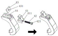
请结合图4和图5,为了使能够提供不同大小的阻尼力(缓冲力),需要调节弹性复位件3的扭力或者叫预紧力来适应不同的使用需求。因此,还包括一可调距组件4,所述弹性复位件3一端通过所述可调距组件4连接于所述第一旋转件11,另一端连接于所述第二旋转件12;所述可调距组件4包括滑槽44、限位固定座43、调距滑块41和调距螺纹件42;其中,所述滑槽44开设于所述第一旋转件11的自由端;所述限位固定座43设于所述滑槽44并被限止于所述滑槽44的滑动方向,所述限位固定座43上设有穿孔431;所述调距滑块41滑动设于所述滑槽44内并面向所述穿孔431处开设有螺纹孔411,所述弹性复位件3连接于所述调距滑块41;所述调距螺纹件42的一端穿设于所述穿孔431并螺接于所述螺纹孔411,所述调距螺纹件42的另一端具有止挡于所述限位固定座43的止挡部421。通过调距螺纹件42在调距滑块41中的螺纹深度来带动调距滑块41在滑槽44中的位置,实现弹性复位件3的预拉伸,众所周知的是,弹性带来的弹力是随着弹性件的拉伸而等比提高,所以起到调节扭力大小的作用来适应不同的适用对象。Please refer to Figure 4 and Figure 5. In order to provide damping force (buffering force) of different sizes, it is necessary to adjust the torsion force or preload force of the
作为本实施例一较佳的实施方式,所述限位固定座43还可以设于所述第一旋转件11的自由端上,在本实施例中未予以具体图示,但本领域人员应该得知的是,限位固定座43作为配合调距螺纹件42的止挡部421提供调距支点的构件,核心作用是保持位置不变,设于滑槽44或第一旋转件11自由端是一种实际选择。As a preferred implementation of this embodiment, the
作为本实施例一较佳的实施方式,所述弹性复位件3包括但不限于弹簧或者弹性橡胶树脂。其他的能够实现弹性拉伸并复位的构件理论上也可被采纳使用。As a preferred implementation of this embodiment, the elastic restoring
以上提供的方案在外部构件连接在内撑异构件2进行旋转时,足以完成用力的阻尼缓冲和复位的助力。The solution provided above is sufficient to achieve the damping and buffering of the force and the assisting of the reset when the outer member is connected to the inner support
然而,单就上述记载的方案虽能够达到目的效果,但是还不够稳定,不能起到一个限位保护的作用。因此,本发明还包括一连杆5,所述连杆5包括杆体52和安装壳体51,所述杆体52一端连接于所述安装壳体51,另一端连接于外部结构;所述旋转外扩组件位于所述安装壳体51内,所述旋转外扩组件的外扩限度被所述安装壳体51的壳壁限定。安装壳体51的主要作用一是配合下述枢接轴13防止旋转外扩组件的易位,另一方面是给旋转外扩组件的外扩设定一个限制和极限,使外扩到一定程度即限止。However, although the above-mentioned solution alone can achieve the desired effect, it is not stable enough to play a role in limiting protection. Therefore, the present invention also includes a connecting
作为本实施例一较佳实施方式,还包括一转轴14和枢接轴13;所述转轴14设于所述安装壳体51内,所述内撑异构件2设于所述转轴14上;所述第一旋转件11上设有第一枢接孔,所述第二旋转件12上设有第二枢接孔,所述第一枢接孔和所述第二枢接孔相互配合对齐后安装于所述枢接轴13上。连杆5是为了方便安装,将转轴14安装在连杆5上,使得内撑异构件2的旋转相比于没有转轴14,更加的稳定,但不是说没有转轴14或不能唯一确定使用转轴14就不能达到旋转的效果;枢接轴13安装在连杆5上也是为了旋转外扩组件的工作稳定,枢接点不会易位。As a preferred implementation of this embodiment, it also includes a
作为本实施例一较佳实施方式,还包括一滑动轴承15,所述滑动轴承15的内圈套设于所述转轴14上,所述内撑异构件2设有安装口21,所述滑动轴承15的外圈固定于所述安装口21内。滑动轴承15是为了减少不必要的摩擦力,浪费用力做功。As a preferred implementation of this embodiment, it further includes a sliding
作为本实施例一较佳实施方式,所述可外扩舱室的形状匹配于所述内撑异构件2的形状。所述内撑异构件2为一长方块,所述长方体的一相对两面被设置为弧形面。As a preferred implementation of this embodiment, the shape of the externally expandable cabin matches the shape of the
本发明还公开了一种上述旋转缓冲助力机构在外骨骼关节康复锻炼中进行缓冲力和助力的应用。具体的,只要涉及关节的多自由度运动,能够利用到本发明的阻尼力缓冲和复位助力的原理,本发明旋转缓冲助力机构都有理由被利用。本发明可针对不同体型所需,能够调节关节扭力大小,带有缓冲和复位功能的外骨骼关节方案。The invention also discloses an application of the above-mentioned rotating buffering boosting mechanism to buffer force and boosting in exoskeleton joint rehabilitation exercise. Specifically, as long as the multi-degree-of-freedom motion of the joint is involved, the principles of damping force buffering and reset assisting of the present invention can be utilized, and the rotating buffering assisting mechanism of the present invention has a reason to be used. The present invention is an exoskeleton joint scheme with buffering and repositioning functions, which can adjust the torque of the joints according to the needs of different body shapes.
应用实施例:Application example:
1、旋转缓冲助力机构在外骨骼肩关节康复锻炼中进行缓冲力和助力的应用,可以对手臂的摆动进行康复训练,具体的,将本机构适应性绑在肩部,手臂与内撑异构件2联动即可实现,本实施例未予以具体图示,但本领域技术人员能够无疑义得出。1. The application of the rotating buffering power-assisting mechanism in the exoskeleton shoulder joint rehabilitation exercise for buffering force and power-assisting can be used for rehabilitation training of the arm swing. Specifically, the mechanism is adaptively tied to the shoulder, and the arm and the inner support are different components. 2. The linkage can be realized. This embodiment is not shown in detail, but those skilled in the art can draw it without doubt.
2、旋转缓冲助力机构在外骨骼踝关节康复锻炼中进行缓冲力和助力的应用,可以对足部作出跖屈/背曲进行足部踝关节康复训练,具体的,将本机构适应性安装在踝关节,本效果实施例由下述技术方案一同呈现。2. The application of the rotating buffering assist mechanism in the rehabilitation of exoskeleton ankle joints for cushioning and assisting, can perform plantar flexion/dorsiflexion of the foot for foot and ankle rehabilitation training. Specifically, the mechanism is adaptively installed on the ankle. Joints, this effect embodiment is presented together with the following technical solutions.
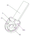
请结合图1、图2、图3和图4,本发明还公开了一种外骨骼踝关节缓冲助力装置,包括小腿连杆6、鞋履组件7和上述的旋转缓冲助力机构;所述小腿连杆6连接于所述内撑异构件2,所述鞋履组件7连接于所述旋转外扩组件。本发明通过将所述小腿连杆6连接于所述内撑异构件2,所述鞋履组件7连接于所述旋转外扩组件;当足部做出跖屈动作和背屈动作,驱使内撑异构件2在可外扩舱室内旋转时,会对第一旋转件11和第二旋转件12施加一个向外扩张的力让两个自由端远离,使得弹性复位件3随着两个旋转件的自由端远离时被拉伸;此时,内撑异构件2施加力做功被转化成弹性势能存储,存储过程中起到了一个缓冲和阻尼的作用,当外力结束后,弹性势能被释放转化为动能帮助两个旋转件的自由端靠近,起到助力的作用。Please refer to Fig. 1, Fig. 2, Fig. 3 and Fig. 4, the present invention also discloses an exoskeleton ankle joint buffering and assisting device, including a
以下通过附图和具体实施方式来对本发明进行进一步的描述:The present invention is further described below through the accompanying drawings and specific embodiments:
为了使旋转缓冲助力机构能够适应性安装于踝关节,作为本实施例一较佳实施方式,还包括一连杆5,所述连杆5包括杆体52和安装壳体51,所述连杆5一端连接于所述安装壳体51,另一端连接于所述鞋履组件7,所述小腿连杆6连接于所述内撑异构件2。从而使得足部与小腿的相对转动被作用于内撑异构件2和旋转外扩组件。In order to enable the rotation buffering power-assisting mechanism to be adaptively installed on the ankle joint, as a preferred implementation of this embodiment, a connecting
进一步的,所述旋转外扩组件位于所述安装壳体51内,所述旋转外扩组件的外扩限度被所述安装壳体51的壳壁限定。安装壳体51的主要作用一是防止旋转外扩组件的易位,另一方面是给旋转外扩组件的外扩设定一个限制和极限,进而对足部做出跖屈动作和背屈动作进行限度保护。Further, the rotating outer expansion assembly is located in the installation casing 51 , and the outer expansion limit of the rotating outer expansion assembly is defined by the shell wall of the installation casing 51 . The main function of installing the housing 51 is to prevent the translocation of the rotating external expansion component, and to set a limit and limit for the external expansion of the rotating external expansion component, so as to perform plantar flexion and dorsiflexion of the foot. limited protection.
作为本实施例一较佳实施方式,还包括一转轴14和枢接轴13;所述转轴14设于所述安装壳体51内,所述内撑异构件2设于所述转轴14上;所述第一旋转件11上设有第一枢接孔,所述第二旋转件12上设有第二枢接孔,所述第一枢接孔和所述第二枢接孔相互配合对齐后安装于所述枢接轴13上。连杆5是为了方便安装,将转轴14安装在连杆5上,使得内撑异构件2的旋转相比于没有转轴14,更加的稳定,但不是说没有转轴14或不能唯一确定使用转轴14就不能达到旋转的效果;枢接轴13安装在连杆5上也是为了旋转外扩组件的工作稳定,枢接点不会易位,但并不是说枢接轴13不安装在连杆5上就不能实现,只是相对来说不能足够稳定,但也能足以实现旋转外扩组件的外扩。As a preferred implementation of this embodiment, it also includes a
作为本实施例一较佳实施方式,还包括一滑动轴承15,所述滑动轴承15的内圈套设于所述转轴14上,所述内撑异构件2设有安装口21,所述滑动轴承15的外圈固定于所述安装口21内。滑动轴承15是为了减少不必要的摩擦力,浪费用力做功。As a preferred implementation of this embodiment, it further includes a sliding
请结合图4和图6,作为本实施例一较佳实施方式,小腿连杆6包括小腿连接杆体61和连接于小腿连接杆体61的安装壳座62,所述内撑异构件2设于所述安装壳座62内,且内撑异构件2的外壁与安装壳座62的内壁之间设有加固肋板621,所述内撑异构件2的所述安装口21安装于转轴14之后通过卡簧8进行固定。4 and 6, as a preferred implementation of this embodiment, the lower
作为本实施例一较佳实施方式,所述可外扩舱室的形状匹配于所述内撑异构件2的形状,配合内撑异构件2内的安装口21形成一个“0”形异构件。所述内撑异构件2为一长方块,所述长方体的一相对两面被设置为弧形面。As a preferred implementation of this embodiment, the shape of the externally expandable cabin matches the shape of the
请结合图7、图8和图9,本实施例作用于踝关节的原理为:Please refer to Figure 7, Figure 8 and Figure 9, the principle of this embodiment acting on the ankle joint is:
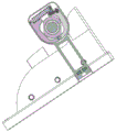
初始状态时,小腿连杆6与连杆5成180°夹角,第一旋转件11与第二旋转件12以转轴14支点在弹性复位件3的作用下,抱紧小腿连杆6的内撑异构件2。In the initial state, the
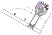
当足部做出跖屈动作时,小腿连杆6上的内撑异构件2支撑打开第一旋转件11和第二旋转件12,带动弹性复位件3拉伸,存储弹性势能。当旋转外扩组件的外侧与安装壳体51的内侧壁接触时,实现跖屈角度的限位,此时回转释放弹性势能,实现助力。When the foot performs plantar flexion, the
当足部做出背屈动作时,其原理和跖屈动作一样,不再多述。When the foot performs dorsiflexion, its principle is the same as that of plantar flexion, so it will not be described further.
当用户体型差异较大或其它原因,需要对踝关节缓冲进行调整时,可在初始状态时,调节调距螺纹件42,带动调距滑块41滑动,改变弹性复位件3的预紧张力,变换踝关节处的扭力数值,实现缓冲调整。When there is a big difference in the user's body shape or other reasons, it is necessary to adjust the ankle joint cushioning, in the initial state, adjust the
需要说明的是,本说明书所附图式所绘示的结构、比例、大小等,均仅用以配合说明书所揭示的内容,以供熟悉此技术的人士了解与阅读,并非用以限定本发明可实施的限定条件,故不具技术上的实质意义,任何结构的修饰、比例关系的改变或大小的调整,在不影响本发明所能产生的功效及所能达成的目的下,均应仍落在本发明所揭示的技术内容得能涵盖的范围内。同时,本说明书中所引用的如“上”、“下”、“左”、“右”、“中间”及“一”等的用语,亦仅为便于叙述的明了,而非用以限定本发明可实施的范围,其相对关系的改变或调整,在无实质变更技术内容下,当亦视为本发明可实施的范畴。It should be noted that the structures, proportions, sizes, etc. shown in the drawings attached in this specification are only used to cooperate with the contents disclosed in the specification, so as to be understood and read by those who are familiar with the technology, and are not intended to limit the present invention. The limited conditions that can be implemented have no technical significance. Any modification of the structure, change of the proportional relationship or adjustment of the size should still fall within the scope of the present invention without affecting the effect and the purpose that the present invention can achieve. It is within the scope that the technical content disclosed in the present invention can cover. At the same time, the terms such as "up", "down", "left", "right", "middle" and "one" quoted in this specification are only for the convenience of description and clarity, and are not used to limit this specification. The implementable scope of the invention, and the change or adjustment of the relative relationship thereof, shall also be regarded as the implementable scope of the present invention without substantially changing the technical content.
本领域中普通技术人员可根据上述说明对本发明做出多种变化。因而,在不违反本发明的权利要求宗旨的前提下,实施例中的某些细节不应构成对本发明的限定,本发明将以所附权利要求书界定的范围作为保护范围。Numerous variations of the present invention can be made by those of ordinary skill in the art in light of the above description. Therefore, under the premise of not violating the spirit of the claims of the present invention, some details in the embodiments should not be construed to limit the present invention, and the present invention will take the scope defined by the appended claims as the protection scope.
Claims (10)
Priority Applications (4)
| Application Number | Priority Date | Filing Date | Title |
|---|---|---|---|
| CN202011037284.3A CN111920650B (en) | 2020-09-28 | 2020-09-28 | Rotary buffering power-assisted mechanism and exoskeleton ankle joint buffering power-assisted device |
| US18/027,923 US12558281B2 (en) | 2020-09-28 | 2021-08-05 | Rotating cushioning and assisting mechanism and an exoskeleton ankle joint cushioning and assisting device |
| EP21871083.8A EP4197514B1 (en) | 2020-09-28 | 2021-08-05 | Rotary buffering power-assisted mechanism and exoskeleton ankle-joint-buffering power-assisted device |
| PCT/CN2021/110784 WO2022062706A1 (en) | 2020-09-28 | 2021-08-05 | Rotary buffering power-assisted mechanism and exoskeleton ankle-joint-buffering power-assisted device |
Applications Claiming Priority (1)
| Application Number | Priority Date | Filing Date | Title |
|---|---|---|---|
| CN202011037284.3A CN111920650B (en) | 2020-09-28 | 2020-09-28 | Rotary buffering power-assisted mechanism and exoskeleton ankle joint buffering power-assisted device |
Publications (2)
| Publication Number | Publication Date |
|---|---|
| CN111920650A true CN111920650A (en) | 2020-11-13 |
| CN111920650B CN111920650B (en) | 2021-01-08 |
Family
ID=73333660
Family Applications (1)
| Application Number | Title | Priority Date | Filing Date |
|---|---|---|---|
| CN202011037284.3A Active CN111920650B (en) | 2020-09-28 | 2020-09-28 | Rotary buffering power-assisted mechanism and exoskeleton ankle joint buffering power-assisted device |
Country Status (4)
| Country | Link |
|---|---|
| US (1) | US12558281B2 (en) |
| EP (1) | EP4197514B1 (en) |
| CN (1) | CN111920650B (en) |
| WO (1) | WO2022062706A1 (en) |
Cited By (2)
| Publication number | Priority date | Publication date | Assignee | Title |
|---|---|---|---|---|
| CN113693803A (en) * | 2021-07-30 | 2021-11-26 | 杭州程天科技发展有限公司 | Ankle correction wearing equipment |
| WO2022062706A1 (en) * | 2020-09-28 | 2022-03-31 | 上海傅利叶智能科技有限公司 | Rotary buffering power-assisted mechanism and exoskeleton ankle-joint-buffering power-assisted device |
Families Citing this family (2)
| Publication number | Priority date | Publication date | Assignee | Title |
|---|---|---|---|---|
| CN116276899B (en) * | 2023-01-31 | 2023-08-29 | 哈尔滨商业大学 | A robot joint device |
| CN119526364B (en) * | 2025-01-17 | 2025-05-27 | 昆明理工大学 | An exoskeleton arm that suppresses resting tremors |
Citations (21)
| Publication number | Priority date | Publication date | Assignee | Title |
|---|---|---|---|---|
| EP0027762A1 (en) * | 1979-10-18 | 1981-04-29 | ETABLISSEMENTS MAYZAUD Maurice | Anti-adductus short articulated boot |
| DE3610570A1 (en) * | 1986-03-27 | 1987-10-01 | Gerd Dr Jungkunz | Sports and training device for strengthening the jumping power of the foot during the jumping phase |
| DE4038511A1 (en) * | 1990-12-03 | 1992-06-04 | Gerd Dr Jungkunz | Training appts. for increasing spring force when jumping - has two plastics shells with abutments and interchangeable adjustable tension spring |
| WO1993009734A1 (en) * | 1991-11-14 | 1993-05-27 | Takumi Hino | Joint for human body-attaching devices and human body-attaching device |
| US5242379A (en) * | 1990-07-02 | 1993-09-07 | Exoflex, Inc. | Ankle brace with floating pivot hinge |
| US5267924A (en) * | 1993-01-07 | 1993-12-07 | Advanced Kinetics, Inc. | Apparatus and method for imparting continuous passive motion to the foot |
| US5348532A (en) * | 1991-09-24 | 1994-09-20 | Ipos Gmbh & Co. Kg | Orthopedic redressment splint |
| US5520627A (en) * | 1993-06-30 | 1996-05-28 | Empi, Inc. | Range-of-motion ankle splint |
| US20030093018A1 (en) * | 2000-02-10 | 2003-05-15 | Erich Albrecht | Orthesis comprising a flexion and an extension stop that can be adjusted by means of rail pivoting movements |
| EP1053767B1 (en) * | 1999-05-05 | 2005-05-04 | Giuseppe Carbone | Fitness equipment for carrying out exercises involving the muscles and the articulations of the legs |
| CN101829005A (en) * | 2010-05-24 | 2010-09-15 | 哈尔滨工程大学 | Gait rehabilitation robot footrest device with metatarsal joints |
| CN104771292A (en) * | 2015-03-17 | 2015-07-15 | 浙江大学 | Wearable quasi-passive ankle joint exoskeleton recovery device |
| US9398970B1 (en) * | 2010-02-05 | 2016-07-26 | Grant C. Meyer | Rooster boot ankle foot orthosis |
| CN106236502A (en) * | 2016-08-04 | 2016-12-21 | 沈研 | A kind of portable passive ankle pump training aids |
| WO2017050824A1 (en) * | 2015-09-23 | 2017-03-30 | Albrecht Gmbh | Dynamic joint support |
| CN207462306U (en) * | 2017-04-06 | 2018-06-08 | 西安交通大学医学院第一附属医院 | Prevent the ankle flexion movement device of lower limb vein thrombus |
| CN108784902A (en) * | 2018-03-07 | 2018-11-13 | 陈秀莲 | A kind of multi-functional hemiplegic patient's legs and feet ankle orthosis panel assembly |
| CN109381841A (en) * | 2017-08-02 | 2019-02-26 | 三星电子株式会社 | Exercise aid device |
| US20190224031A1 (en) * | 2018-01-22 | 2019-07-25 | Adrian Dunca | Ankle rehabilitation device |
| CN111249047A (en) * | 2020-01-17 | 2020-06-09 | 武汉尚诚源健康科技有限公司 | A stepless adjustment ankle correction plate |
| CN210991569U (en) * | 2019-08-01 | 2020-07-14 | 遵义医学院附属医院 | An anti-rotation exercise device for lower extremity thrombosis prevention |
Family Cites Families (38)
| Publication number | Priority date | Publication date | Assignee | Title |
|---|---|---|---|---|
| US2295758A (en) * | 1941-05-12 | 1942-09-15 | Truman S Safford | Brake adjuster |
| FR2589360B1 (en) * | 1985-10-30 | 1987-12-24 | Chareire Jean Louis | APPARATUS FOR MECHANICAL ASSISTANCE OF LEG PROPULSION |
| US5031606A (en) * | 1991-01-17 | 1991-07-16 | Randolph Austin Company | Brace and hinge apparatus and method |
| DE19645076A1 (en) * | 1996-10-31 | 1998-05-14 | Albrecht Gmbh | Device for reducing extension or flexion deficits of a distal limb compared to a proximal limb |
| CN101021239B (en) | 2007-01-09 | 2010-05-26 | 任秀军 | Drum type brake for prolonging friction lining service life |
| US10314680B2 (en) * | 2010-04-06 | 2019-06-11 | Horsepower Technologies Inc. | Limb protection device |
| US9480618B2 (en) * | 2010-10-05 | 2016-11-01 | Elizabeth T. Hsiao-Wecksler | Portable active pneumatically powered ankle-foot orthosis |
| JP5633577B2 (en) * | 2010-11-26 | 2014-12-03 | トヨタ自動車株式会社 | Torsional vibration damping device |
| JP5316708B2 (en) * | 2010-12-16 | 2013-10-16 | トヨタ自動車株式会社 | Walking support device |
| US11400010B2 (en) * | 2011-07-29 | 2022-08-02 | Leonis Medical Corporation | Method and system for control and operation of motorized orthotic exoskeleton joints |
| US9539168B2 (en) * | 2012-08-01 | 2017-01-10 | Gary Lawrence Johnston | Leg therapy apparatus |
| WO2014092162A1 (en) * | 2012-12-14 | 2014-06-19 | 国立大学法人名古屋工業大学 | Walking assistance machine |
| US10251451B2 (en) * | 2013-03-05 | 2019-04-09 | Boa Technology Inc. | Closure devices including incremental release mechanisms and methods therefor |
| MX361630B (en) * | 2013-04-10 | 2018-12-13 | Ultraflex Systems Inc | A bi-directional dampening and assisting unit. |
| ES2776374T3 (en) * | 2014-07-18 | 2020-07-30 | Univ Brussel Vrije | Prosthesis or orthosis comprising a hinge joint system to functionally assist, enhance and / or replace a hinge joint of a human or animal subject |
| CN104161610B (en) | 2014-08-03 | 2016-07-06 | 浙江大学 | The ankle joint of ectoskeleton buffering power-assisted |
| JP5807888B1 (en) | 2015-01-28 | 2015-11-10 | 有限会社出水義肢装具製作所 | Prosthetic joint joint joint |
| KR101677935B1 (en) * | 2015-04-07 | 2016-11-22 | 주식회사 에스지메카트로닉스 | Joint Driving Unit And Joint Structure Of Lower-limb Assistance Robot Having The Same |
| US10518404B2 (en) * | 2015-07-17 | 2019-12-31 | Lockheed Martin Corporation | Variable force exoskeleton hip joint |
| CN105616113B (en) | 2016-02-23 | 2017-10-20 | 东南大学 | A kind of passive energy storage foot mechanism for lower limb assistance exoskeleton |
| US11096816B2 (en) * | 2016-04-04 | 2021-08-24 | Ossur Iceland Ehf | Orthopedic device |
| EP3442472B1 (en) * | 2016-04-14 | 2021-12-08 | Marquette University | Passive ankle prosthesis with energy return |
| EP3525729B1 (en) * | 2016-10-13 | 2023-08-02 | Dephy, Inc. | Unidirectional actuated exoskeleton device |
| KR101836413B1 (en) * | 2016-10-28 | 2018-03-09 | 재단법인대구경북과학기술원 | Tendon device of suit type exoskeleton for human power assistance |
| US10912666B2 (en) * | 2016-12-08 | 2021-02-09 | University Of Washington | Energy storage device for an exoskeleton |
| JP6816622B2 (en) * | 2017-04-11 | 2021-01-20 | トヨタ自動車株式会社 | Joint control device |
| US11491074B2 (en) * | 2017-07-17 | 2022-11-08 | Carnegie Mellon University | Exoskeleton device emulation system |
| IT201700081177A1 (en) * | 2017-07-18 | 2019-01-18 | Iuvo S R L | "Operator assistance assistance system" |
| IT201700084346A1 (en) * | 2017-07-24 | 2019-01-24 | Scuola Superiore Santanna | ASSISTABLE WALKING ASSISTED DEVICE |
| DE102017124337B4 (en) * | 2017-10-18 | 2019-05-23 | Ottobock Se & Co. Kgaa | Orthopedic technical joint |
| US12036669B2 (en) * | 2018-03-08 | 2024-07-16 | Apptronik, Inc. | Exoskeleton device with improved actuation system |
| DE102018204597B4 (en) | 2018-03-27 | 2021-01-14 | Audi Ag | Valve drive for an internal combustion engine and a corresponding internal combustion engine |
| US10973670B2 (en) * | 2018-06-08 | 2021-04-13 | Industrial Technology Research Institute | Adjustable brace |
| CN111084681A (en) | 2018-10-24 | 2020-05-01 | 北京工道风行智能技术有限公司 | Hydraulic Bionic Ankle |
| CN109262596B (en) | 2018-11-19 | 2020-10-27 | 西安交通大学 | Power-assisted exoskeleton robot |
| PL3897477T3 (en) * | 2018-12-20 | 2024-09-23 | Djo, Llc | MOTION LIMITING BRACE AND HOW TO USE IT |
| CN209662127U (en) * | 2019-01-31 | 2019-11-22 | 深圳市迈步机器人科技有限公司 | A kind of exoskeleton ankle joint mechanism and exoskeleton system |
| CN111920650B (en) * | 2020-09-28 | 2021-01-08 | 上海傅利叶智能科技有限公司 | Rotary buffering power-assisted mechanism and exoskeleton ankle joint buffering power-assisted device |
-
2020
- 2020-09-28 CN CN202011037284.3A patent/CN111920650B/en active Active
-
2021
- 2021-08-05 US US18/027,923 patent/US12558281B2/en active Active
- 2021-08-05 EP EP21871083.8A patent/EP4197514B1/en active Active
- 2021-08-05 WO PCT/CN2021/110784 patent/WO2022062706A1/en not_active Ceased
Patent Citations (21)
| Publication number | Priority date | Publication date | Assignee | Title |
|---|---|---|---|---|
| EP0027762A1 (en) * | 1979-10-18 | 1981-04-29 | ETABLISSEMENTS MAYZAUD Maurice | Anti-adductus short articulated boot |
| DE3610570A1 (en) * | 1986-03-27 | 1987-10-01 | Gerd Dr Jungkunz | Sports and training device for strengthening the jumping power of the foot during the jumping phase |
| US5242379A (en) * | 1990-07-02 | 1993-09-07 | Exoflex, Inc. | Ankle brace with floating pivot hinge |
| DE4038511A1 (en) * | 1990-12-03 | 1992-06-04 | Gerd Dr Jungkunz | Training appts. for increasing spring force when jumping - has two plastics shells with abutments and interchangeable adjustable tension spring |
| US5348532A (en) * | 1991-09-24 | 1994-09-20 | Ipos Gmbh & Co. Kg | Orthopedic redressment splint |
| WO1993009734A1 (en) * | 1991-11-14 | 1993-05-27 | Takumi Hino | Joint for human body-attaching devices and human body-attaching device |
| US5267924A (en) * | 1993-01-07 | 1993-12-07 | Advanced Kinetics, Inc. | Apparatus and method for imparting continuous passive motion to the foot |
| US5520627A (en) * | 1993-06-30 | 1996-05-28 | Empi, Inc. | Range-of-motion ankle splint |
| EP1053767B1 (en) * | 1999-05-05 | 2005-05-04 | Giuseppe Carbone | Fitness equipment for carrying out exercises involving the muscles and the articulations of the legs |
| US20030093018A1 (en) * | 2000-02-10 | 2003-05-15 | Erich Albrecht | Orthesis comprising a flexion and an extension stop that can be adjusted by means of rail pivoting movements |
| US9398970B1 (en) * | 2010-02-05 | 2016-07-26 | Grant C. Meyer | Rooster boot ankle foot orthosis |
| CN101829005A (en) * | 2010-05-24 | 2010-09-15 | 哈尔滨工程大学 | Gait rehabilitation robot footrest device with metatarsal joints |
| CN104771292A (en) * | 2015-03-17 | 2015-07-15 | 浙江大学 | Wearable quasi-passive ankle joint exoskeleton recovery device |
| WO2017050824A1 (en) * | 2015-09-23 | 2017-03-30 | Albrecht Gmbh | Dynamic joint support |
| CN106236502A (en) * | 2016-08-04 | 2016-12-21 | 沈研 | A kind of portable passive ankle pump training aids |
| CN207462306U (en) * | 2017-04-06 | 2018-06-08 | 西安交通大学医学院第一附属医院 | Prevent the ankle flexion movement device of lower limb vein thrombus |
| CN109381841A (en) * | 2017-08-02 | 2019-02-26 | 三星电子株式会社 | Exercise aid device |
| US20190224031A1 (en) * | 2018-01-22 | 2019-07-25 | Adrian Dunca | Ankle rehabilitation device |
| CN108784902A (en) * | 2018-03-07 | 2018-11-13 | 陈秀莲 | A kind of multi-functional hemiplegic patient's legs and feet ankle orthosis panel assembly |
| CN210991569U (en) * | 2019-08-01 | 2020-07-14 | 遵义医学院附属医院 | An anti-rotation exercise device for lower extremity thrombosis prevention |
| CN111249047A (en) * | 2020-01-17 | 2020-06-09 | 武汉尚诚源健康科技有限公司 | A stepless adjustment ankle correction plate |
Cited By (3)
| Publication number | Priority date | Publication date | Assignee | Title |
|---|---|---|---|---|
| WO2022062706A1 (en) * | 2020-09-28 | 2022-03-31 | 上海傅利叶智能科技有限公司 | Rotary buffering power-assisted mechanism and exoskeleton ankle-joint-buffering power-assisted device |
| CN113693803A (en) * | 2021-07-30 | 2021-11-26 | 杭州程天科技发展有限公司 | Ankle correction wearing equipment |
| CN113693803B (en) * | 2021-07-30 | 2023-09-01 | 杭州程天科技发展有限公司 | Ankle correction wearing equipment |
Also Published As
| Publication number | Publication date |
|---|---|
| WO2022062706A1 (en) | 2022-03-31 |
| EP4197514A4 (en) | 2024-01-24 |
| EP4197514A1 (en) | 2023-06-21 |
| CN111920650B (en) | 2021-01-08 |
| US12558281B2 (en) | 2026-02-24 |
| US20230372180A1 (en) | 2023-11-23 |
| EP4197514B1 (en) | 2025-10-01 |
Similar Documents
| Publication | Publication Date | Title |
|---|---|---|
| WO2022062706A1 (en) | Rotary buffering power-assisted mechanism and exoskeleton ankle-joint-buffering power-assisted device | |
| CN104644381B (en) | A three-degree-of-freedom flexible ankle joint device for exoskeleton | |
| US11638673B2 (en) | Hip-knee passive exoskeleton device based on clutch time-sharing control | |
| CN105616113B (en) | A kind of passive energy storage foot mechanism for lower limb assistance exoskeleton | |
| WO2021109205A1 (en) | Rigid-flexible hybrid exoskeleton | |
| CN113478466B (en) | A passive lower extremity exoskeleton with load conduction and walking energy saving | |
| CN110559162B (en) | Lower limb exoskeleton driver | |
| CN111745624A (en) | A passive power-assisted exoskeleton load-bearing robot | |
| CN105643598B (en) | The semi-passive lower limb exoskeleton of energy-conservation driven based on lasso trick | |
| CN108095976A (en) | A kind of bionic knee joint device for healing and training with passively rebound | |
| CN111906752B (en) | A passive exoskeleton robot for enhanced human payload transport | |
| CN111419652B (en) | Power-source-free knee joint mechanism | |
| CN108670732B (en) | A hemiplegia auxiliary walking device | |
| CN108938338B (en) | Three-degree-of-freedom ankle joint device of exoskeleton robot | |
| CN107625565A (en) | Wearable active bionical artificial limb anklebone joint mechanism based on metamorphic mechanisms | |
| CN114434421A (en) | Active and passive combined wearable lower limb assistance exoskeleton device | |
| CN114571439A (en) | Compact type joint braking lower limb assistance exoskeleton device | |
| CN204501524U (en) | A kind of ectoskeleton three-degree of freedom flexible ankle device | |
| CN215021619U (en) | Hip joint torsional spring booster unit | |
| CN110623817A (en) | Unpowered hip joint energy storage walking aid exoskeleton | |
| CN217091328U (en) | An ankle joint device and exoskeleton system | |
| CN218488396U (en) | A kind of knee joint load-reducing device | |
| CN207578393U (en) | A kind of exoskeleton robot | |
| CN211442538U (en) | A walking structure of a humanoid biped robot | |
| CN205054518U (en) | A foot device for dressing formula low limbs ectoskeleton robot |
Legal Events
| Date | Code | Title | Description |
|---|---|---|---|
| PB01 | Publication | ||
| PB01 | Publication | ||
| SE01 | Entry into force of request for substantive examination | ||
| SE01 | Entry into force of request for substantive examination | ||
| GR01 | Patent grant | ||
| GR01 | Patent grant | ||
| CP03 | Change of name, title or address |
Address after: 201315 No. 12, Xiu Pu Road, Pudong New Area, Shanghai, 1st floor, Room 101, 2nd floor Patentee after: Shanghai Fourier Intelligent Technology Co.,Ltd. Country or region after: China Address before: Room 101, 1st and 2nd floors, Building 12, No. 2388 Xiupu Road, Pudong New Area, Shanghai Patentee before: SHANGHAI FOURIER INTELLIGENCE Co.,Ltd. Country or region before: China |
|
| CP03 | Change of name, title or address |