CN111982980A - Boiler pipeline leakage detection device - Google Patents
Boiler pipeline leakage detection device Download PDFInfo
- Publication number
- CN111982980A CN111982980A CN202010773748.0A CN202010773748A CN111982980A CN 111982980 A CN111982980 A CN 111982980A CN 202010773748 A CN202010773748 A CN 202010773748A CN 111982980 A CN111982980 A CN 111982980A
- Authority
- CN
- China
- Prior art keywords
- detection device
- water
- conductivity detection
- conductivity
- boiler
- Prior art date
- Legal status (The legal status is an assumption and is not a legal conclusion. Google has not performed a legal analysis and makes no representation as to the accuracy of the status listed.)
- Pending
Links
Images


Classifications
-
- G—PHYSICS
- G01—MEASURING; TESTING
- G01N—INVESTIGATING OR ANALYSING MATERIALS BY DETERMINING THEIR CHEMICAL OR PHYSICAL PROPERTIES
- G01N27/00—Investigating or analysing materials by the use of electric, electrochemical, or magnetic means
- G01N27/02—Investigating or analysing materials by the use of electric, electrochemical, or magnetic means by investigating impedance
- G01N27/04—Investigating or analysing materials by the use of electric, electrochemical, or magnetic means by investigating impedance by investigating resistance
- G01N27/06—Investigating or analysing materials by the use of electric, electrochemical, or magnetic means by investigating impedance by investigating resistance of a liquid
Landscapes
- Chemical & Material Sciences (AREA)
- Chemical Kinetics & Catalysis (AREA)
- Electrochemistry (AREA)
- Physics & Mathematics (AREA)
- Health & Medical Sciences (AREA)
- Life Sciences & Earth Sciences (AREA)
- Analytical Chemistry (AREA)
- Biochemistry (AREA)
- General Health & Medical Sciences (AREA)
- General Physics & Mathematics (AREA)
- Immunology (AREA)
- Pathology (AREA)
- Investigating Or Analyzing Materials By The Use Of Electric Means (AREA)
Abstract
本申请涉及一种锅炉管道泄漏检测装置,涉及锅炉检测领域,其括依次通过管道连接的第一电导率检测装置、阳离子交换柱、第二电导率检测装置、脱气装置和第三电导率检测装置,所述脱气装置包括管道依次连接的换热器、加热器和水气分离器,所述水气分离器通过管道连接至所述换热器,从水气分离器输出的水样与进入加热器前的水样在换热器中进行热量交换,第一电导率检测装置用于检测初始的氢电导率σ1,第二电导率检测装置用于检测阳离子交换后的氢电导率σ2,第三电导率检测装置用于检测脱气氢电导率σ3。本申请能够检测锅炉水的腐蚀性以及锅炉内是否泄漏。
The present application relates to a boiler pipeline leakage detection device, and relates to the field of boiler detection, which includes a first conductivity detection device, a cation exchange column, a second conductivity detection device, a degassing device and a third conductivity detection device which are sequentially connected through pipes The degassing device includes a heat exchanger, a heater and a water-gas separator connected in sequence by pipelines, the water-gas separator is connected to the heat exchanger through a pipeline, and the water sample output from the water-gas separator is The water sample before entering the heater undergoes heat exchange in the heat exchanger. The first conductivity detection device is used to detect the initial hydrogen conductivity σ 1 , and the second conductivity detection device is used to detect the hydrogen conductivity σ after cation exchange. 2. The third conductivity detection device is used to detect the conductivity σ 3 of degassed hydrogen. The application can detect the corrosiveness of boiler water and whether there is leakage in the boiler.
Description
技术领域technical field
本申请涉及锅炉检测的技术领域,尤其是涉及一种锅炉管道泄漏检测装置。The present application relates to the technical field of boiler detection, and in particular, to a boiler pipeline leak detection device.
背景技术Background technique
锅炉的主要工作原理是一种利用燃料燃烧后释放的热能或工业生产中的余热传递给容器内的水,使水达到所需要的温度或一定压力蒸汽的热力设备。多用于火电站、船舶、机车和工矿企业。The main working principle of the boiler is a thermal equipment that uses the heat energy released after the combustion of fuel or the waste heat in industrial production to transfer to the water in the container, so that the water can reach the required temperature or a certain pressure of steam. It is mostly used in thermal power stations, ships, locomotives and industrial and mining enterprises.
锅炉水中的钙、镁离子较多时,容易结生水垢,水垢会引起锅炉腐蚀,造成炉管泄漏,锅炉内的高压气体会进入进入到泄漏的炉管中,锅炉腐蚀会缩短锅炉的使用寿命,造成安全隐患。氢电导率是表征锅炉水纯度及浸蚀性的重要指标,指被测水样中阳离子被转换为H+后对其电导率进行监测所得的电导率值。现有的检测方式一般通过氢电导率来反应水对锅炉的腐蚀性,但无法直接判断锅炉是否已经发生泄漏。When there are many calcium and magnesium ions in the boiler water, it is easy to form scale. The scale will cause the boiler to corrode and cause the leakage of the furnace tube. The high-pressure gas in the boiler will enter into the leaking furnace tube, and the boiler corrosion will shorten the service life of the boiler. cause a safety hazard. Hydrogen conductivity is an important indicator to characterize the purity and corrosiveness of boiler water. It refers to the conductivity value obtained by monitoring the conductivity after the cations in the tested water sample are converted into H + . The existing detection method generally reflects the corrosiveness of water to the boiler through the hydrogen conductivity, but it is impossible to directly judge whether the boiler has leaked.
发明内容SUMMARY OF THE INVENTION
针对现有技术存在的不足,本申请提供一种锅炉管道泄漏检测装置,能够检测锅炉水的腐蚀性以及锅炉内是否泄漏。In view of the shortcomings of the prior art, the present application provides a boiler pipeline leakage detection device, which can detect the corrosiveness of boiler water and whether there is leakage in the boiler.
本申请的上述效果是通过以下技术方案得以实现的:The above-mentioned effects of the present application are achieved through the following technical solutions:
一种锅炉泄漏检测装置,包括依次通过管道连接的第一电导率检测装置、阳离子交换柱、第二电导率检测装置、脱气装置和第三电导率检测装置,所述脱气装置包括管道依次连接的换热器、加热器和水气分离器,所述水气分离器通过管道连接至所述换热器,从水气分离器输出的水样与进入加热器前的水样在换热器中进行热量交换,第一电导率检测装置用于检测初始的氢电导率σ1,第二电导率检测装置用于检测阳离子交换后的氢电导率σ2,第三电导率检测装置用于检测脱气氢电导率σ3。A boiler leakage detection device, comprising a first conductivity detection device, a cation exchange column, a second conductivity detection device, a degassing device and a third conductivity detection device connected in sequence through pipelines, the degassing device comprising pipelines in sequence A connected heat exchanger, a heater and a water-gas separator, the water-gas separator is connected to the heat exchanger through a pipeline, and the water sample output from the water-gas separator is in heat exchange with the water sample before entering the heater Heat exchange is carried out in the device, the first conductivity detection device is used to detect the initial hydrogen conductivity σ 1 , the second conductivity detection device is used to detect the hydrogen conductivity σ 2 after cation exchange, and the third conductivity detection device is used for Degassed hydrogen conductivity σ 3 was detected.
通过采用上述技术方案,第一电导率检测装置测得的检测值σ1为锅炉水初始状态的阳离子导电率,锅炉水经过阳离子交换柱后,水中阳离子被置换为H+,第二导电率检测装置的检测值σ2为阳离子置换后的氢电导率,计算σ2-σ1=Δ1,Δ1能够反映锅炉水中阳离子的含量,阳离子含量越高,锅炉水对锅炉的腐蚀能力越强,反之越弱;若锅炉管道发生泄漏,炉内气体会溶解到锅炉水中,锅炉水经过脱气装置加热后,二氧化碳从水中分离出,第三导电率检测装置的检测值为脱去二氧化碳的脱气氢电导率σ3,计算σ2-σ3=Δ2,Δ2能够反映锅炉水中二氧化碳的含量,从而反映锅炉中的气体是否泄漏至锅炉水中;脱气装置的加热器对锅炉水加热,降低气体在水中的溶解度,从而使气体脱离,脱气后的锅炉水需要进行降温,然后检测脱气氢电导率σ3,水样先后进入换热器进行热量交换,进入加热器前的水样能够进行预加热,提高加热器的加热速度,排出水气分离器的水样能够降低温度,以便检测脱气氢电导率σ3,该设置能够简化设备结构,节省能源。By adopting the above technical solution, the detection value σ1 measured by the first conductivity detection device is the cation conductivity of the boiler water in the initial state. After the boiler water passes through the cation exchange column, the cations in the water are replaced by H + , and the second conductivity detects The detected value σ 2 of the device is the hydrogen conductivity after cation replacement. Calculate σ 2 -σ 1 =Δ 1 , Δ 1 can reflect the content of cations in boiler water. The higher the cation content, the stronger the corrosion ability of boiler water to the boiler. On the contrary, the weaker; if the boiler pipeline leaks, the gas in the furnace will dissolve into the boiler water. After the boiler water is heated by the degassing device, the carbon dioxide is separated from the water. The detection value of the third conductivity detection device is the degassed carbon dioxide removed. Hydrogen conductivity σ 3 , calculate σ 2 -σ 3 =Δ 2 , Δ 2 can reflect the content of carbon dioxide in the boiler water, so as to reflect whether the gas in the boiler leaks into the boiler water; the heater of the degassing device heats the boiler water, reducing the The solubility of the gas in water, so that the gas is separated, the degassed boiler water needs to be cooled, and then the degassed hydrogen conductivity σ 3 is detected. The water sample enters the heat exchanger successively for heat exchange, and the water sample before entering the heater can Pre-heating is performed to increase the heating speed of the heater, and the temperature of the water sample discharged from the water-gas separator can be lowered so as to detect the conductivity σ 3 of degassed hydrogen. This setting can simplify the equipment structure and save energy.
本申请进一步设置为:所述水气分离器包括罐体,所述罐体内设置有气液分离网,所述气液分离网将罐体内分隔为上腔室和下腔室,所述罐体上开设有与所述上腔室连通的进水口和出气口,以及与所述下腔室连通的出水口,水样从所述进水口进入上腔室,然后经过所述气液分离网进入下腔室并从出水口排出,水样中的气体被气液分离网分隔在上腔室中,并从出气口排出。The present application is further provided as follows: the water-gas separator includes a tank body, and a gas-liquid separation net is arranged in the tank body, and the gas-liquid separation net divides the tank body into an upper chamber and a lower chamber, and the tank body The upper part is provided with a water inlet and an air outlet that communicate with the upper chamber, and a water outlet communicated with the lower chamber. The water sample enters the upper chamber from the water inlet, and then enters through the gas-liquid separation net. The lower chamber is discharged from the water outlet, and the gas in the water sample is separated in the upper chamber by the gas-liquid separation net and discharged from the gas outlet.
通过采用上述技术方案,水样从水气分离器的进水口进入上腔室,然后经过气液分离网进入下腔室,并从出水口排出,从水样逸出的气体从出气口排出,气液分离网能够阻隔气体,进一步防止泡沫等少量气体进入下腔室中,从而提高脱气氢电导率σ3的准确性。By adopting the above technical solution, the water sample enters the upper chamber from the water inlet of the water-gas separator, then enters the lower chamber through the gas-liquid separation net, and is discharged from the water outlet, and the gas escaping from the water sample is discharged from the air outlet, The gas-liquid separation net can block the gas and further prevent a small amount of gas such as foam from entering the lower chamber, thereby improving the accuracy of the degassed hydrogen conductivity σ3.
本申请进一步设置为:所述水气分离器的出气口连接有水封。The present application is further provided that: the air outlet of the water-gas separator is connected with a water seal.
通过采用上述技术方案,水封能够防止外界空气从出气口倒吸至水气分离器的上腔体中,影响水气分离的效率。By adopting the above technical solution, the water seal can prevent the outside air from being sucked back from the air outlet into the upper cavity of the water-gas separator, thereby affecting the efficiency of water-gas separation.
本申请进一步设置为:所述第一电导率检测装置的上游管道安装有水泵。The present application is further provided that: a water pump is installed on the upstream pipeline of the first conductivity detection device.
通过采用上述技术方案,水泵将水样泵送至本申请的管道中。By adopting the above technical solution, the water sample is pumped into the pipeline of the present application by the water pump.
本申请进一步设置为:所述第一电导率检测装置的上游管道安装有流量阀。The present application further provides that: a flow valve is installed on the upstream pipeline of the first conductivity detection device.
通过采用上述技术方案,流量阀能够控制进入本申请中的水样的流量,流量过大则阳离子交换柱效率不足,导致检测数据不准确,流量过小则检测效率低。By adopting the above technical solution, the flow valve can control the flow rate of the water sample entering the present application. If the flow rate is too large, the efficiency of the cation exchange column will be insufficient, resulting in inaccurate detection data. If the flow rate is too small, the detection efficiency will be low.
本申请进一步设置为:所述第一电导率检测装置的上游管道安装有流量计。The present application further provides that: a flow meter is installed on the upstream pipeline of the first conductivity detection device.
通过采用上述技术方案,流量计能够检测水样的流量,以便在流量过大或过小时,通过流量阀将水样调整在合适范围。By adopting the above technical solution, the flowmeter can detect the flow rate of the water sample, so that when the flow rate is too large or too small, the water sample can be adjusted in an appropriate range through the flow valve.
本申请进一步设置为:所述阳离子交换柱内盛放有强酸型阳离子树脂。The present application is further configured as follows: a strong acid type cation resin is contained in the cation exchange column.
通过采用上述技术方案,强酸型阳离子树脂离解能力强,在酸性溶液中能够离解并进行离子交换作用。By adopting the above technical scheme, the strong acid type cation resin has strong dissociation ability, and can dissociate and perform ion exchange in an acidic solution.
本申请进一步设置为:还包括控制器和显示器,所述控制器与第一电导率检测装置、第二电导率检测装置、第三电导率检测装置以及显示器连接,所述第一电导率检测装置、第二电导率检测装置和第三电导率检测装置向所述控制器传送信号,所述控制器向所述显示器传送信号。The present application is further configured to further include a controller and a display, wherein the controller is connected to the first conductivity detection device, the second conductivity detection device, the third conductivity detection device and the display, the first conductivity detection device , the second conductivity detection device and the third conductivity detection device transmit signals to the controller, which transmits signals to the display.
通过采用上述技术方案,显示器能够显示第一电导率检测装置、第二电导率检测装置、第三电导率检测装置的检测数值,以便于工作人员直接获取数值。By adopting the above technical solution, the display can display the detection values of the first conductivity detection device, the second conductivity detection device, and the third conductivity detection device, so that the staff can directly obtain the values.
本申请进一步设置为:所述第一电导率检测装置、所述阳离子交换柱、所述第二电导率检测装置、所述第三电导率检测装置、所述控制器以及所述显示器均固定连接在安装板的一侧,所述脱气装置以及大部分管道都固定连接在安装板的另一侧,所述安装板底部固定连接有接水槽,所述接水槽位于脱气装置所在的安装板一侧,所述接水槽的槽底连接有排水管。The present application further provides that: the first conductivity detection device, the cation exchange column, the second conductivity detection device, the third conductivity detection device, the controller and the display are all fixedly connected On one side of the mounting plate, the degassing device and most of the pipes are fixedly connected to the other side of the mounting plate, and a water receiving groove is fixedly connected to the bottom of the mounting plate, and the water receiving groove is located on the mounting plate where the degassing device is located On one side, a drain pipe is connected to the bottom of the water receiving tank.
通过采用上述技术方案,当位于安装板一侧的脱气装置和大部分的管道漏水时,水能够滴落至接水槽中,并通过排水管排出,方便于清理。By adopting the above technical solution, when the degassing device located on one side of the mounting plate and most of the pipes leak water, the water can drip into the water receiving tank and be discharged through the drain pipe, which is convenient for cleaning.
综上所述,本申请包括以下至少一种有益技术效果:To sum up, the present application includes at least one of the following beneficial technical effects:
1.第一电导率检测装置检测锅炉水初始状态的阳离子导电率σ1,第二导电率检测装置检测阳离子转换后的氢电导率的检测值σ2,计算σ2-σ1=Δ1,Δ1能够反映锅炉水对锅炉的腐蚀能力强弱;第三导电率检测装置检测脱去二氧化碳的脱气氢电导率σ3,计算σ2-σ3=Δ2,Δ2能够反映锅炉中的气体是否泄漏至锅炉水中;换热器能够对进入加热器前的水样进行预加热,并对排出水气分离器的水样进行温度,简化了设备结构,并节省了能源;1. The first conductivity detection device detects the cation conductivity σ 1 in the initial state of the boiler water, the second conductivity detection device detects the hydrogen conductivity value σ 2 after cation conversion, and calculates σ 2 -σ 1 =Δ 1 , Δ 1 can reflect the corrosion ability of boiler water to the boiler; the third conductivity detection device detects the conductivity σ 3 of degassed hydrogen from which carbon dioxide has been removed, and calculates σ 2 -σ 3 =Δ 2 , and Δ 2 can reflect the electrical conductivity in the boiler. Whether the gas leaks into the boiler water; the heat exchanger can preheat the water sample before entering the heater, and conduct the temperature of the water sample discharged from the water-gas separator, which simplifies the equipment structure and saves energy;
2.水气分离器的气液分离网能够阻隔气体,提高脱气效果,从而提高脱气氢电导率σ3的准确性;2. The gas-liquid separation net of the water-gas separator can block the gas and improve the degassing effect, thereby improving the accuracy of the degassed hydrogen conductivity σ3;
3.显示器能够显示第一电导率检测装置、第二电导率检测装置、第三电导率检测装置的检测数值,以便于工作人员直接获取数值。3. The display can display the detection values of the first conductivity detection device, the second conductivity detection device, and the third conductivity detection device, so that the staff can directly obtain the values.
附图说明Description of drawings
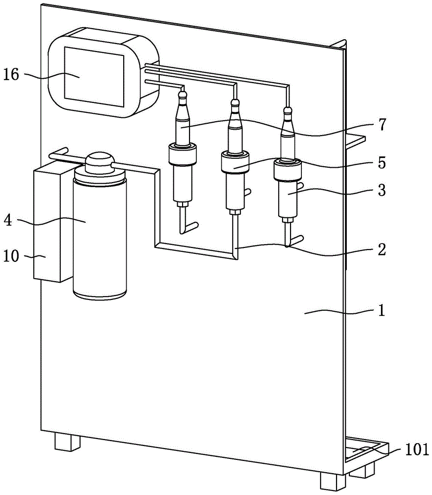
图1是锅炉管道泄漏检测装置的安装板的阳离子交换柱所在一侧的结构示意图。FIG. 1 is a schematic structural diagram of the side where the cation exchange column of the installation plate of the boiler pipeline leak detection device is located.
图2是锅炉管道泄漏检测装置的安装板的脱气装置所在一侧的结构示意图。Fig. 2 is a schematic view of the structure of the side where the degassing device of the installation plate of the boiler pipeline leak detection device is located.
图3是锅炉管道泄漏检测装置的整体连接结构示意图。Figure 3 is a schematic diagram of the overall connection structure of the boiler pipeline leak detection device.
图4是锅炉管道泄漏检测装置的水气分离器的结构示意图。FIG. 4 is a schematic structural diagram of the water-gas separator of the boiler pipeline leak detection device.
图5是锅炉管道泄漏检测装置的水封的结构示意图。FIG. 5 is a schematic structural diagram of the water seal of the boiler pipeline leak detection device.
图6是锅炉管道泄漏检测装置的控制器的控制原理图。Fig. 6 is a control principle diagram of the controller of the boiler pipe leakage detection device.
附图标记:1、安装板;101、接水槽;102、排水管;2、管道;3、第一电导率检测装置;4、阳离子交换柱;5、第二电导率检测装置;6、脱气装置;601、换热器;602、加热器;603、水气分离器;6031、罐体;6032、气液分离网;6033、上腔室;6034、下腔室;6035、进水口;6036、出气口;6037、出水口;7、第三电导率检测装置;8、流量阀;9、水泵;10、流量计;11、水封;1101、水容器;1102、进气管;1103、出气管;15、控制器;16、显示器。Reference numerals: 1. Mounting plate; 101. Water receiving tank; 102. Drain pipe; 2. Pipeline; 3. First conductivity detection device; 4. Cation exchange column; 5. Second conductivity detection device; Gas device; 601, heat exchanger; 602, heater; 603, water gas separator; 6031, tank body; 6032, gas-liquid separation net; 6033, upper chamber; 6034, lower chamber; 6035, water inlet; 6036, air outlet; 6037, water outlet; 7, third conductivity detection device; 8, flow valve; 9, water pump; 10, flow meter; 11, water seal; 1101, water container; 1102, air inlet pipe; 1103, Outlet pipe; 15. Controller; 16. Display.
具体实施方式Detailed ways
以下结合附图对本申请作进一步详细说明。The present application will be further described in detail below with reference to the accompanying drawings.
参照图1和图2,为本申请公开的一种锅炉管道泄漏检测装置,包括安装板1,安装板1上固定设置有通过管道2依次连接的第一电导率检测装置3、阳离子交换柱4、第二电导率检测装置5、脱气装置6和第三电导率检测装置7。检测装置的具体的连接结构原理图参照附图3所示。将锅炉中的水样通入管道2中,第一电导率检测装置3用于首先检测水样的初始的氢电导率σ1,阳离子交换柱4中放置有强酸型阳离子树脂,用于将水样中的阳离子置换为H+,第二电导率检测装置5用于检测水样经过阳离子交换后的氢电导率σ2,脱气装置6用于脱离溶于水样中的二氧化碳气体,第三电导率检测装置7用于检测水样的脱气氢电导率σ3。Referring to FIGS. 1 and 2 , a boiler pipeline leak detection device disclosed in the present application includes a mounting
水中的Ga+、Mg+等阳离子能够造成锅炉的腐蚀,计算阳离子置交换后的氢电导率σ2与初始的氢电导率σ1的差值,即σ2-σ1=Δ1,Δ1能够反映锅炉水中阳离子的含量,Δ1值越高则阳离子含量越高,锅炉水对锅炉的腐蚀能力越强,反之越弱。锅炉正常工作状态下,要求氢电导率σ2不高于0.20.06μS/cm。当锅炉已经腐蚀且炉管发生泄漏时,会有气体进入到锅炉水中,计算阳离子置交换后的氢电导率σ2与脱气氢电导率σ3的差值,即σ2-σ3=Δ2,Δ2能够反映锅炉水中二氧化碳的含量,从而反映锅炉的泄漏情况,锅炉正常工作状态下,要求Δ2不超过0.06μS/cm。The cations such as Ga+ and Mg+ in the water can cause corrosion of the boiler. Calculate the difference between the hydrogen conductivity σ2 after cation exchange and the initial hydrogen conductivity σ1, that is, σ2-σ1=Δ1, Δ1 can reflect the content of cations in the boiler water, The higher the Δ1 value, the higher the cation content, the stronger the corrosive ability of boiler water to the boiler, and vice versa. Under the normal working state of the boiler, the hydrogen conductivity σ2 is required not to be higher than 0.20.06μS/cm. When the boiler is corroded and the furnace tube leaks, gas will enter the boiler water. Calculate the difference between the hydrogen conductivity σ2 after cation exchange and the degassed hydrogen conductivity σ3, that is, σ2-σ3=Δ2, Δ2 can reflect The content of carbon dioxide in the boiler water reflects the leakage of the boiler. Under the normal working state of the boiler, Δ2 is required not to exceed 0.06μS/cm.
参照图1和图2,第一电导率检测装置3的上游管道2上还依次连接有流量阀8、水泵9和流量计10。水泵9用于将水样泵送至检测装置的管道2中,流量计10用于显示水样的流量,流量阀8用于调节水样的流量,水样流量过大会导致阳离子交换柱4效率不足,从而检测数据不准确,水样流量过小会导致检测效率低,通过流量阀8能够将水样流量控制在适应阳离子交换柱4工作效率范围内。1 and 2 , a
参照图2,脱气装置6包括通过管道2依次连接的换热器601、加热器602和水气分离器603,水样经过第二电导率检测装置5后进入换热器601中,然后进入加热器602,加热器602将水样加热至100°C,使水样中的二氧化碳气体逸出,然后进入水气分离器603,分离水样中逸出的二氧化碳。Referring to FIG. 2, the
参照图4,水气分离器603包括罐体6031,罐体6031内设置有气液分离网6032,气液分离网6032为金属网,水样能够在气液分离网6032上铺摊,增加与空气的接触面积,有利于二氧化碳逸出。气液分离网6032将罐体6031内分隔为上腔室6033和下腔室6034,罐体6031顶部开设有进水口6035和出气口6036,进水口6035和出气口6036与上腔室6033连通,罐体6031底部开设有出水口6037,出水口6027与下腔室6034连通。4, the water-
参照图3,水样从水气分离器603的进水口6035进入上腔室6033,然后经过气液分离网6032进入下腔室6034,再从出水口6037排出,水样中逸出的二氧化碳气体从出气口6036排出。水样经过水气分离器603后温度依然较高,在进入第三电导率检测装置7前需要降低温度,出水口6037通过管道2连接至换热器601,高温水样在换热器601中与进入加热器602之前的水样进行热量交换,水样在进入加热器602之前能够预加热至40°C-50°C,从而能够在加热器602中快速加热至100°C,水样离开水气分离器603后,能够在换热器601中降温至40°C-50°C,达到第三电导率检测装置7需要的检测温度。换热器601的设置即实现了水样的预加热,又实现了水样的降温,简化了设备结构,并节省了能源。3, the water sample enters the
参照图2和图5,水气分离器603的出气口6036连接有水封11,水封11包括水容器1101、进气管1102和出气管1103,进气管1102的下端伸入水容器1101内并靠近于水容器1101底部,进气管1102的上端从水容器1101顶部穿出,并通过管道2与水气分离器603的出气口6036连接,出气管1103的下端连通于水容器1101的顶部且不穿入水容器1101内,另一端可以连接排水的管道2。水容器1101内盛放有没过进气管1102下端的积水,从水气分离器603排出气口6036排出的气体和水汽从进气管1102进入水容器1101中,并通过出水管排出,水容器1101内的积水能够防止外界气体倒吸至水气分离器603中,影响水气分离的效率。2 and 5 , the
参照图1和图6,安装板1上还安装有控制器15(未在图中显示)和显示器16,控制器15与第一电导率检测装置3、第二电导率检测装置5、第三电导率检测装置7以及显示器16连接,第一电导率检测装置3、第二电导率检测装置5和第三电导率检测装置7检测出σ1、σ2和σ3 的数值后,向控制器15传送信号,控制器15然后向显示器16传送信号,显示器16上从而显示σ1、σ2和σ3 的数值,以便于工作人员直接获取数值。1 and 6, a controller 15 (not shown in the figure) and a
参照图1和图2,安装板1竖直设置,流量计10、阳离子交换柱4、第一电导率检测装置3、第二电导率检测装置5、第三电导率检测装置7、控制器15以及显示器16均固定连接在安装板1的一侧,流量阀8、水泵9、换热器601、加热器602、水气分离器603、水封11以及大部分管道2都固定连接在安装板1的另一侧。安装板1的底部固定连接有接水槽101,接水槽101水平设置,且位于安装板1的大部分管道2所在的一侧,接水槽101的槽底连接有排水管102。当安装板1上接水槽101所在一侧的部件漏水时,水能够滴落到接水槽101中,并通过排水管102排出。1 and 2 , the mounting
本申请中的锅炉管道泄漏检测装置可以持续通入水样,实时监测锅炉内的腐蚀情况,也可以间隔的通入水样进行检测。间隔检测时,应当先通入水样一段时间,对检测装置进行冲洗,然后再读取显示器16上的数值,减小前一次检测时残留的水样对本次检测造成影响。The boiler pipeline leak detection device in the present application can continuously feed water samples to monitor the corrosion situation in the boiler in real time, and can also feed water samples at intervals for detection. During interval detection, the water sample should be passed in for a period of time to rinse the detection device, and then read the value on the
本具体实施方式的实施例均为本申请的较佳实施例,并非依此限制本申请的保护范围,故:凡依本申请的结构、形状、原理所做的等效变化,均应涵盖于本申请的保护范围之内。The embodiments of this specific embodiment are all preferred embodiments of the present application, and do not limit the protection scope of the present application accordingly. Therefore: all equivalent changes made according to the structure, shape and principle of the present application should be covered in within the scope of protection of this application.
Claims (9)
Priority Applications (1)
| Application Number | Priority Date | Filing Date | Title |
|---|---|---|---|
| CN202010773748.0A CN111982980A (en) | 2020-08-04 | 2020-08-04 | Boiler pipeline leakage detection device |
Applications Claiming Priority (1)
| Application Number | Priority Date | Filing Date | Title |
|---|---|---|---|
| CN202010773748.0A CN111982980A (en) | 2020-08-04 | 2020-08-04 | Boiler pipeline leakage detection device |
Publications (1)
| Publication Number | Publication Date |
|---|---|
| CN111982980A true CN111982980A (en) | 2020-11-24 |
Family
ID=73445472
Family Applications (1)
| Application Number | Title | Priority Date | Filing Date |
|---|---|---|---|
| CN202010773748.0A Pending CN111982980A (en) | 2020-08-04 | 2020-08-04 | Boiler pipeline leakage detection device |
Country Status (1)
| Country | Link |
|---|---|
| CN (1) | CN111982980A (en) |
Cited By (1)
| Publication number | Priority date | Publication date | Assignee | Title |
|---|---|---|---|---|
| CN116718323A (en) * | 2023-06-12 | 2023-09-08 | 西安热工研究院有限公司 | A real-time monitoring and diagnosis method and device for leakage of heating network heater in power plant |
Citations (11)
| Publication number | Priority date | Publication date | Assignee | Title |
|---|---|---|---|---|
| JPH1130564A (en) * | 1997-07-10 | 1999-02-02 | Kansai Electric Power Co Inc:The | Seawater leak detector |
| CN101066517A (en) * | 2007-06-05 | 2007-11-07 | 浙江大学 | Gas-water separator |
| CN101070991A (en) * | 2006-05-11 | 2007-11-14 | 叶萍 | Energy-saving thermoelectric heater device |
| CN203577476U (en) * | 2013-10-29 | 2014-05-07 | 中国石油化工集团公司 | Hydrogen sulfide-resistant and acid corrosion-resistant water diversion separator |
| WO2014140993A1 (en) * | 2013-03-15 | 2014-09-18 | Koninklijke Philips N.V. | Sensing a characteristic of aqueous solution |
| CN205516730U (en) * | 2015-12-21 | 2016-08-31 | 云南滇金投资有限公司 | Solid water gas separat device of abacusing |
| CN106644678A (en) * | 2017-01-23 | 2017-05-10 | 北京华科仪科技股份有限公司 | Method and apparatus for measuring power plant water degassed cation conductivity |
| CN107648939A (en) * | 2017-10-17 | 2018-02-02 | 太仓塑料助剂厂有限公司 | The waste gas recovering device of cumyl peroxide |
| CN208959566U (en) * | 2018-10-15 | 2019-06-11 | 北京苏瑞海科技有限公司 | High efficient gas and liquid separator system and its efficient wire mesh demister |
| CN110763734A (en) * | 2019-10-18 | 2020-02-07 | 河北冀研能源科学技术研究院有限公司 | Volatile permeation membrane method for removing CO2Hydrogen conductivity measuring device |
| CN110806428A (en) * | 2019-10-21 | 2020-02-18 | 华电电力科学研究院有限公司 | A special pH measuring device for cooling water system in a generator and its working method |
-
2020
- 2020-08-04 CN CN202010773748.0A patent/CN111982980A/en active Pending
Patent Citations (11)
| Publication number | Priority date | Publication date | Assignee | Title |
|---|---|---|---|---|
| JPH1130564A (en) * | 1997-07-10 | 1999-02-02 | Kansai Electric Power Co Inc:The | Seawater leak detector |
| CN101070991A (en) * | 2006-05-11 | 2007-11-14 | 叶萍 | Energy-saving thermoelectric heater device |
| CN101066517A (en) * | 2007-06-05 | 2007-11-07 | 浙江大学 | Gas-water separator |
| WO2014140993A1 (en) * | 2013-03-15 | 2014-09-18 | Koninklijke Philips N.V. | Sensing a characteristic of aqueous solution |
| CN203577476U (en) * | 2013-10-29 | 2014-05-07 | 中国石油化工集团公司 | Hydrogen sulfide-resistant and acid corrosion-resistant water diversion separator |
| CN205516730U (en) * | 2015-12-21 | 2016-08-31 | 云南滇金投资有限公司 | Solid water gas separat device of abacusing |
| CN106644678A (en) * | 2017-01-23 | 2017-05-10 | 北京华科仪科技股份有限公司 | Method and apparatus for measuring power plant water degassed cation conductivity |
| CN107648939A (en) * | 2017-10-17 | 2018-02-02 | 太仓塑料助剂厂有限公司 | The waste gas recovering device of cumyl peroxide |
| CN208959566U (en) * | 2018-10-15 | 2019-06-11 | 北京苏瑞海科技有限公司 | High efficient gas and liquid separator system and its efficient wire mesh demister |
| CN110763734A (en) * | 2019-10-18 | 2020-02-07 | 河北冀研能源科学技术研究院有限公司 | Volatile permeation membrane method for removing CO2Hydrogen conductivity measuring device |
| CN110806428A (en) * | 2019-10-21 | 2020-02-18 | 华电电力科学研究院有限公司 | A special pH measuring device for cooling water system in a generator and its working method |
Cited By (1)
| Publication number | Priority date | Publication date | Assignee | Title |
|---|---|---|---|---|
| CN116718323A (en) * | 2023-06-12 | 2023-09-08 | 西安热工研究院有限公司 | A real-time monitoring and diagnosis method and device for leakage of heating network heater in power plant |
Similar Documents
| Publication | Publication Date | Title |
|---|---|---|
| CN101477843B (en) | High temperature high pressure water circulation system | |
| CN1590981B (en) | Method for manufacturing heat exchanger tube corrosion monitoring sensor | |
| CN204882440U (en) | Degasification hydrogen conductivity measuring device | |
| CN217359268U (en) | Degassing conductivity detection device | |
| CN102435546B (en) | Supercritical autoclave bubbling deoxygenation system | |
| CN113981470A (en) | PEM hydrogen production test system and PEM hydrogen production test process | |
| CN111982980A (en) | Boiler pipeline leakage detection device | |
| CN108105753A (en) | A kind of dry cooling oxygen remover dead steam recovery system | |
| CN201359593Y (en) | High-temperature and high-pressure water circulating system | |
| CN212514376U (en) | Boiler pipeline leakage detection device | |
| CN203502327U (en) | Device and system for monitoring corrosion of thermodynamic system of thermal power generating unit on line | |
| CN105334155B (en) | A kind of steel Macroscopic tissue heat acid attack device | |
| CN101995316A (en) | Method for detecting slight leakage of condenser | |
| CN211345280U (en) | A boiler heat deaerator system | |
| CN218573642U (en) | Outer wall temperature monitoring and controlling means of high temperature reaction furnace | |
| CN112146819A (en) | Hydrogen conductivity measuring device and method for condenser leak detection device | |
| RU2417357C1 (en) | Tightness control device | |
| CN117054002A (en) | Monitoring system and method for safe operation of heat supply network | |
| CN111593152A (en) | A method for rapid leak detection of blast furnace cooling stave damage | |
| CN206786692U (en) | A kind of pressure-maintaining nitrogen-charging anti-corrosion device for industrial boilers | |
| CN205351285U (en) | Waste heat boiler hunt leak on line device, online leak detection system and waste heat boiler system | |
| CN214584791U (en) | A dynamic simulation test device for performance evaluation of ultra-high temperature thermal network scale and corrosion inhibitor | |
| CN211013760U (en) | Water sample sampling system for determining conductivity | |
| CN202048821U (en) | Energy-saving secondary steam buffer tank for circulating water monitoring heat exchanger | |
| CN204986957U (en) | Boiler equipment |
Legal Events
| Date | Code | Title | Description |
|---|---|---|---|
| PB01 | Publication | ||
| PB01 | Publication | ||
| SE01 | Entry into force of request for substantive examination | ||
| SE01 | Entry into force of request for substantive examination | ||
| RJ01 | Rejection of invention patent application after publication | ||
| RJ01 | Rejection of invention patent application after publication |
Application publication date: 20201124 |