CN111987705A - Direct current energy consumption system, electric power system and energy consumption method - Google Patents
Direct current energy consumption system, electric power system and energy consumption method Download PDFInfo
- Publication number
- CN111987705A CN111987705A CN201910421563.0A CN201910421563A CN111987705A CN 111987705 A CN111987705 A CN 111987705A CN 201910421563 A CN201910421563 A CN 201910421563A CN 111987705 A CN111987705 A CN 111987705A
- Authority
- CN
- China
- Prior art keywords
- switch
- branch
- power
- node
- energy consumption
- Prior art date
- Legal status (The legal status is an assumption and is not a legal conclusion. Google has not performed a legal analysis and makes no representation as to the accuracy of the status listed.)
- Pending
Links
Images




Classifications
-
- H—ELECTRICITY
- H02—GENERATION; CONVERSION OR DISTRIBUTION OF ELECTRIC POWER
- H02H—EMERGENCY PROTECTIVE CIRCUIT ARRANGEMENTS
- H02H9/00—Emergency protective circuit arrangements for limiting excess current or voltage without disconnection
- H02H9/04—Emergency protective circuit arrangements for limiting excess current or voltage without disconnection responsive to excess voltage
- H02H9/042—Emergency protective circuit arrangements for limiting excess current or voltage without disconnection responsive to excess voltage comprising means to limit the absorbed power or indicate damaged over-voltage protection device
-
- H—ELECTRICITY
- H02—GENERATION; CONVERSION OR DISTRIBUTION OF ELECTRIC POWER
- H02J—ELECTRIC POWER NETWORKS; CIRCUIT ARRANGEMENTS OR SYSTEMS FOR SUPPLYING OR DISTRIBUTING ELECTRIC POWER; SYSTEMS FOR STORING ELECTRIC ENERGY
- H02J3/00—Circuit arrangements for AC mains or AC distribution networks
- H02J3/36—Arrangements for transfer of electric power between AC networks via high-voltage DC [HVDC] links; Arrangements for transfer of electric power between generators and networks via HVDC links
-
- Y—GENERAL TAGGING OF NEW TECHNOLOGICAL DEVELOPMENTS; GENERAL TAGGING OF CROSS-SECTIONAL TECHNOLOGIES SPANNING OVER SEVERAL SECTIONS OF THE IPC; TECHNICAL SUBJECTS COVERED BY FORMER USPC CROSS-REFERENCE ART COLLECTIONS [XRACs] AND DIGESTS
- Y02—TECHNOLOGIES OR APPLICATIONS FOR MITIGATION OR ADAPTATION AGAINST CLIMATE CHANGE
- Y02E—REDUCTION OF GREENHOUSE GAS [GHG] EMISSIONS, RELATED TO ENERGY GENERATION, TRANSMISSION OR DISTRIBUTION
- Y02E60/00—Enabling technologies; Technologies with a potential or indirect contribution to GHG emissions mitigation
- Y02E60/60—Arrangements for transfer of electric power between AC networks or generators via a high voltage DC link [HVCD]
Landscapes
- Engineering & Computer Science (AREA)
- Power Engineering (AREA)
- Inverter Devices (AREA)
Abstract
本公开涉及直流耗能系统以及电力系统。提供了一种直流耗能系统,包括:耗能部,其包括耗能装置;以及与所述耗能部串联连接的开关部,所述开关部包括至少一个开关模块,所述开关模块包括:第一节点和第二节点;并联连接在所述第一节点和第二节点之间的开关支路和缓冲支路,其中所述开关支路包括电力电子开关,所述缓冲支路至少包括电容器;以及保护模块,被配置用于保护所述电力电子开关免受过电压和/或过电流。

The present disclosure relates to DC energy consumption systems and power systems. Provided is a DC energy consumption system, comprising: an energy consumption part, which includes an energy consumption device; and a switch part connected in series with the energy consumption part, the switch part includes at least one switch module, and the switch module includes: a first node and a second node; a switch branch and a buffer branch connected in parallel between the first node and the second node, wherein the switch branch includes a power electronic switch, and the buffer branch includes at least a capacitor and a protection module configured to protect the power electronic switch from overvoltage and/or overcurrent.
Description
技术领域technical field
本公开涉及直流耗能系统以及电力系统,以及用于电力系统的耗能方法。The present disclosure relates to a DC energy consumption system and a power system, and an energy consumption method for the power system.
背景技术Background technique
近年来,高压直流输电技术得到高速发展。另一方面,对清洁能源的需求日益增长。风力发电场(也称作风电场)并网柔性直流输电系统(VSC-HVDC,基于电压源换流器的高压直流输电)的应用越来越广泛。In recent years, HVDC technology has developed rapidly. On the other hand, there is a growing demand for clean energy. Wind farms (also called wind farms) are being used more and more widely for grid-connected flexible direct current transmission systems (VSC-HVDC, voltage source converter-based high voltage direct current transmission).
VSC-HVDC在正常运行时,风电机组以孤岛方式接入时发出的能量与受端交流电网消耗的能量保持平衡。而当受端交流电网发生故障时,其能消耗的能量减小,接纳功率的能力受限。而送端风电场由于无法直接获得交流电网的频率和电压信息,短时间内电压和频率不会变化。这导致能量在直流线路上积累,盈余功率流入模块化多电平换流器(MMC),从而使得换流器子模块电容被充电,电压上升,间接导致直流线路电压上升。若受端换流站对直流线路的控制失效,严重时将导致线路跳开。When VSC-HVDC is in normal operation, the energy generated by the wind turbine connected in an island mode is in balance with the energy consumed by the AC grid at the receiving end. When the AC power grid at the receiving end fails, the energy it can consume is reduced, and the ability to receive power is limited. However, since the wind farm at the sending end cannot directly obtain the frequency and voltage information of the AC grid, the voltage and frequency will not change in a short period of time. This causes energy to accumulate on the DC line, and the surplus power flows into the modular multilevel converter (MMC), which causes the converter sub-module capacitors to be charged and the voltage rises, which indirectly causes the DC line voltage to rise. If the control of the DC line by the receiving-end converter station fails, it will cause the line to trip in severe cases.
因此,需要改善的直流耗能系统、电力系统以及耗能方法。Accordingly, there is a need for improved DC energy consumption systems, power systems, and energy consumption methods.
发明内容SUMMARY OF THE INVENTION
根据本公开的一个方面,提供了一种直流耗能系统,包括:耗能部,其包括耗能装置;以及与所述耗能部串联连接的开关部,所述开关部包括至少一个开关模块,所述开关模块包括:第一节点和第二节点;并联连接在所述第一节点和第二节点之间的开关支路和缓冲支路,其中所述开关支路包括电力电子开关,所述缓冲支路至少包括电容器;以及保护模块,被配置用于保护所述电力电子开关免受过电压和/或过电流。According to one aspect of the present disclosure, there is provided a DC energy consumption system, comprising: an energy consumption part including an energy consumption device; and a switch part connected in series with the energy consumption part, the switch part including at least one switch module , the switch module includes: a first node and a second node; a switch branch and a buffer branch connected in parallel between the first node and the second node, wherein the switch branch includes a power electronic switch, so The buffer branch includes at least a capacitor; and a protection module configured to protect the power electronic switch from overvoltage and/or overcurrent.
根据本公开的一个方面,提供了一种直流耗能系统,包括:耗能部,其包括耗能装置;以及与所述耗能部串联连接的开关部,所述开关部包括至少一个开关模块,所述开关模块包括:第一节点和第二节点;连接在所述第一节点和第二节点之间的开关支路,所述开关支路包括电力电子开关;保护模块,被配置用于保护所述电力电子开关免受过电压和/或过电流;以及反向电流保护支路,其与所述开关支路反并联地连接在所述第一节点和第二节点之间,以防止反向电流流过所述开关支路。According to one aspect of the present disclosure, there is provided a DC energy consumption system, comprising: an energy consumption part including an energy consumption device; and a switch part connected in series with the energy consumption part, the switch part including at least one switch module , the switch module comprises: a first node and a second node; a switch branch connected between the first node and the second node, the switch branch comprising a power electronic switch; a protection module configured for protecting the power electronic switch from overvoltage and/or overcurrent; and a reverse current protection branch connected in anti-parallel with the switch branch between the first node and the second node to prevent A reverse current flows through the switch branch.
在一些实施例中,所述至少一个开关模块包括彼此串联的多个所述开关模块。In some embodiments, the at least one switch module includes a plurality of the switch modules in series with each other.
在一些实施例中,所述缓冲支路被配置用于以缓冲所述开关支路上的或所述开关支路中的开关上的电压,并不使直流电流从所述缓冲支路通过。In some embodiments, the snubber branch is configured to buffer voltages on the switch branch or switches in the switch branch without passing direct current from the buffer branch.
在一些实施例中,所述开关部的远离所述耗能部的一端适于连接到直流传输线路,并且所述耗能部被配置为经所述开关部从所述直流传输线路接收电力。In some embodiments, an end of the switching portion remote from the energy consuming portion is adapted to be connected to a DC transmission line, and the energy consuming portion is configured to receive power from the DC transmission line via the switching portion.
在一些实施例中,所述保护模块与所述开关支路并联地连接在所述第一节点和所述第二节点之间。In some embodiments, the protection module is connected in parallel with the switch branch between the first node and the second node.
在一些实施例中,所述保护模块包括金属氧化物避雷器(MOV)。In some embodiments, the protection module includes a metal oxide arrester (MOV).
在一些实施例中,在所述多个开关模块中,处于上游的开关模块的第二节点耦接到与其紧邻的下游开关模块的第一节点。In some embodiments, of the plurality of switch modules, a second node of a switch module that is upstream is coupled to a first node of a downstream switch module that is immediately adjacent thereto.
在一些实施例中,所述耗能装置是集中式电阻性耗能装置,所述耗能部被配置为远离所述开关部,从而使得所述耗能部产生的热量不影响所述开关部。In some embodiments, the energy dissipating device is a centralized resistive energy dissipating device, the energy dissipating portion is configured to be remote from the switching portion such that the heat generated by the energy dissipating portion does not affect the switching portion .
在一些实施例中,所述电力电子开关包括全控型电力电子开关。In some embodiments, the power electronic switch comprises a fully controlled power electronic switch.
在一些实施例中,所述电力电子开关包括下列中的任意一个或多个:IGBT、IGET、IGCT。In some embodiments, the power electronic switch includes any one or more of the following: IGBT, IGET, IGCT.
在一些实施例中,各开关模块还包括:反向电流保护支路,其与所述开关支路反并联地连接在所述第一节点和第二节点之间,以防止反向电流流过所述开关支路。In some embodiments, each switch module further includes: a reverse current protection branch connected in anti-parallel with the switch branch between the first node and the second node to prevent reverse current from flowing through the switch branch.
在一些实施例中,各开关模块还包括:与所述开关支路并联的旁通支路,所述旁通支路包括旁通开关,所述旁通支路被配置用于在所述旁通开关接通时,使得电流从其通过而不经过所述开关支路。In some embodiments, each switch module further includes a bypass branch connected in parallel with the switch branch, the bypass branch includes a bypass switch, the bypass branch is configured to operate in the bypass circuit An on switch is turned on so that current flows therethrough and not through the switch branch.
在一些实施例中,所述开关部的远离所述耗能部的一端适于连接到直流传输线中的高电位直流传输线,所述耗能部的远离所述开关部的一端适于连接到所述直流传输线中的低电位直流传输线,所述直流传输线适于连接到交流电力系统,所述直流耗能系统还包括控制部,所述控制部被配置用于基于所述直流传输线上的电压生成用于各所述开关模块的开关支路的控制信号,以控制各所述开关模块的开关支路的开启,以使得电流通过所述耗能装置以进行耗能。In some embodiments, one end of the switch part away from the energy consumption part is adapted to be connected to a high-potential DC transmission line in the DC transmission line, and one end of the energy consumption part away from the switch part is adapted to be connected to the DC transmission line. a low-potential DC transmission line of the DC transmission lines, the DC transmission line being adapted to be connected to an AC power system, the DC energy consuming system further comprising a control portion configured to generate a voltage based on the DC transmission line A control signal for the switch branch of each of the switch modules to control the opening of the switch branch of each of the switch modules, so that current passes through the energy consumption device for energy consumption.
在一些实施例中,所述至少一个开关模块包括彼此串联的多个所述开关模块,所述直流耗能系统还包括另外的耗能装置,所述另外的耗能装置被配置与所述多个所述开关模块中的一个或多个开关模块并联。In some embodiments, the at least one switch module includes a plurality of the switch modules connected in series with each other, and the DC energy consumption system further includes an additional energy consumption device configured with the plurality of energy consumption devices. One or more of the switch modules are connected in parallel.
在一些实施例中,所述另外的耗能装置包括金属氧化物避雷器。In some embodiments, the additional energy dissipating device includes a metal oxide arrester.
在一些实施例中,所述开关模块还包括连接在所述第一节点和第二节点之间的耗能支路,所述耗能支路包括彼此串联的耗能装置和电力电子开关。In some embodiments, the switch module further includes an energy dissipating branch connected between the first node and the second node, the energy dissipating branch including an energy dissipating device and a power electronic switch connected in series with each other.
根据本公开的一个方面,提供了一种电力系统,包括:直流子系统,所述直流子系统包括直流传输线;以及根据任意实施例所述的直流耗能系统,其连接到所述直流传输线,其中,所述开关部的远离所述耗能部的一端连接到所述直流传输线中的高电位传输线,所述耗能部的远离所述开关部的一端连接到所述直流传输线中的低电位传输线。According to one aspect of the present disclosure, there is provided a power system comprising: a DC subsystem including a DC transmission line; and the DC energy consumption system according to any embodiment, connected to the DC transmission line, Wherein, one end of the switch part away from the energy consumption part is connected to a high potential transmission line in the DC transmission line, and one end of the energy consumption part away from the switch part is connected to a low potential in the DC transmission line Transmission line.
在一些实施例中,所述电力系统还包括:交流子系统,所述交流子系统从所述直流传输线接收电力,并转换成交流电力,所述交流子系统包括直流-交流转换装置。In some embodiments, the power system further includes an AC subsystem that receives power from the DC transmission line and converts it into AC power, the AC subsystem including a DC-AC conversion device.
在一些实施例中,所述电力系统还包括:电力产生或转化系统,被配置用于向所述直流传输线提供直流电力。In some embodiments, the power system further includes a power generation or conversion system configured to provide DC power to the DC transmission line.
在一些实施例中,所述电力产生或转化系统包括下列中的一个:直流发电系统;和交流发电系统以及连接在交流发电系统和所述直流传输线之间的交流-直流转换装置。In some embodiments, the power generation or conversion system includes one of: a direct current power generation system; and an alternating current power generation system and an AC-DC conversion device connected between the alternating current power generation system and the direct current transmission line.
在一些实施例中,所述交流发电系统包括风力发电场。In some embodiments, the alternating current power generation system includes a wind farm.
根据本公开的一个方面,提供了一种电力系统的耗能方法。所述电力系统可以包括:直流子系统,所述直流子系统包括直流传输线;以及根据任意实施例所述的直流耗能系统,其连接到所述直流传输线,其中,所述开关部的远离所述耗能部的一端连接到所述直流传输线中的高电位传输线,所述耗能部的远离所述开关部的一端连接到所述直流传输线中的低电位传输线;以及交流子系统,所述交流子系统从所述直流传输线接收电力,并转换成交流电力。所述方法包括:确定直流传输线上的电压是否超过阈值;在所述直流传输线上的电压超过所述阈值的情况下,基于所述直流传输线上的有功功率和所述交流子系统所消耗的有功功率之间的功率差,生成用于各所述开关模块的开关支路的控制信号;基于所述控制信号控制各所述开关模块的开关支路的开启,以使得电流通过所述耗能装置以进行耗能。According to one aspect of the present disclosure, an energy consumption method of a power system is provided. The power system may include: a DC subsystem, the DC subsystem including a DC transmission line; and the DC energy consumption system according to any embodiment, connected to the DC transmission line, wherein the switch portion is remote from the DC transmission line. One end of the energy consumption part is connected to a high potential transmission line in the DC transmission line, and one end of the energy consumption part away from the switch part is connected to a low potential transmission line in the DC transmission line; and an AC subsystem, the The AC subsystem receives power from the DC transmission line and converts it to AC power. The method includes: determining whether the voltage on the DC transmission line exceeds a threshold; if the voltage on the DC transmission line exceeds the threshold, based on the active power on the DC transmission line and the active power consumed by the AC subsystem The power difference between the powers is used to generate a control signal for the switching branch of each of the switch modules; based on the control signal, the opening of the switch branch of each of the switch modules is controlled, so that the current passes through the energy consuming device to consume energy.
在一些实施例中,生成用于各所述开关模块的开关支路的控制信号包括:基于所述功率差,并基于所述直流传输线上的电压与所述阈值之间的比较,生成所述控制信号。In some embodiments, generating the control signal for the switching branch of each of the switching modules includes generating the said threshold based on the power difference and based on a comparison between the voltage on the DC transmission line and the threshold control signal.
在一些实施例中,生成用于各所述开关模块的开关支路的控制信号包括:基于各开关模块的参数和所述功率差的标幺值对所述功率差进行比例处理,以得到比例处理的功率差;基于比例处理的功率差,以及所述直流传输线上的电压与所述阈值之间的比较,确定用于各所述开关模块的开关支路的控制信号的占空比;基于所述占空比生成脉冲信号,作为用于各所述开关模块的开关支路的所述控制信号。In some embodiments, generating the control signal for the switch branch of each of the switch modules includes: scaling the power difference based on the parameters of each switch module and the per-unit value of the power difference to obtain a proportional the processed power difference; based on the proportionally processed power difference, and the comparison between the voltage on the DC transmission line and the threshold value, determine the duty cycle of the control signal for the switching branch of each of the switching modules; based on The duty cycle generates a pulse signal as the control signal for the switching branch of each of the switching modules.
在一些实施例中,所述方法还包括:基于所述控制信号控制各所述开关模块的开关支路的关断。In some embodiments, the method further includes: controlling switching off of the switching branches of each of the switching modules based on the control signal.
附图说明Description of drawings
附图构成本说明书的一部分,其描述了本公开的示例性实施例,并且连同说明书一起用于解释本发明的原理,在附图中:The accompanying drawings, which constitute a part of this specification, illustrate exemplary embodiments of the present disclosure, and together with the description serve to explain the principles of the invention, in which:
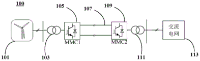
图1示出了一种电力系统的示意图;Figure 1 shows a schematic diagram of a power system;
图2示出了图1所示的电力系统的功率流以及故障的情况的示意图;FIG. 2 shows a schematic diagram of the power flow of the power system shown in FIG. 1 and the situation of a fault;
图3示出了根据本公开一个实施例的耗能系统和并入有该耗能系统的电力系统的示意图;3 shows a schematic diagram of an energy consumption system and a power system incorporating the energy consumption system according to one embodiment of the present disclosure;
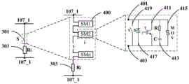
图4示出了根据本公开一个实施例的耗能系统的具体实现方式的示意图;FIG. 4 shows a schematic diagram of a specific implementation of an energy consumption system according to an embodiment of the present disclosure;
图5示出了根据本公开一个实施例的用于电力系统的耗能方法的流程图;FIG. 5 shows a flowchart of an energy consumption method for a power system according to an embodiment of the present disclosure;
图6示出了根据本公开一个实施例的耗能方法的生成控制信号的步骤的一种具体示例;FIG. 6 shows a specific example of a step of generating a control signal in an energy consumption method according to an embodiment of the present disclosure;
图7示出了根据本公开一个实施例的用于耗能系统或包括耗能系统的电力系统的控制部及其控制过程的示意图;以及FIG. 7 shows a schematic diagram of a control unit for an energy consumption system or a power system including an energy consumption system and a control process thereof according to an embodiment of the present disclosure; and
图8-图12示出了根据本公开的实施例的开关的模块的一些变型例。8-12 illustrate some variations of modules of switches according to embodiments of the present disclosure.
具体实施方式Detailed ways
以下结合附图详细地描述本公开的具体实施例。但应理解,对实施例的描述仅仅是说明性的,在任何意义上都不是对本申请所要求保护的发明的限制。除非另有具体说明或者上下文或其原理明示或者暗示,在示例性实施例中的组件和步骤的相对布置、表达式和数值等不作为对本申请所要保护的发明的限制。Specific embodiments of the present disclosure will be described in detail below with reference to the accompanying drawings. It should be understood, however, that the descriptions of the embodiments are merely illustrative and are not intended to limit the invention claimed in this application in any sense. The relative arrangement of components and steps, expressions, numerical values, etc. in the exemplary embodiments are not intended to limit the invention claimed by this application unless otherwise specifically stated or indicated or implied by context or its principles.
本文中所用的术语,仅仅是为了描述特定的实施例,而不意图限制本公开。除非上下文明确地另外指出,本文中所用的单数形式的“一”和“所述”意图同样包括复数形式。还要理解的是,“包含”一词在本文中使用时,说明存在所指出的特征、整体、步骤、操作、单元和/或组件,但是并不排除存在或增加一个或多个其它特征、整体、步骤、操作、单元和/或组件以及/或者它们的组合。另外,在本申请中所提及的“耦接/连接”包括直接耦接和间接耦接;换而言之,“A耦接/连接到B”或者“A与B耦接/连接”包括A与B直接耦接/连接,以及A和B间接耦接/连接并在A和B之间可以存在其他中间元件。The terminology used herein is for the purpose of describing particular embodiments only and is not intended to limit the present disclosure. As used herein, the singular forms "a" and "the" are intended to include the plural forms as well, unless the context clearly dictates otherwise. It is also to be understood that the word "comprising" when used herein indicates the presence of the indicated features, integers, steps, operations, units and/or components, but does not preclude the presence or addition of one or more other features, Entities, steps, operations, units and/or components and/or combinations thereof. In addition, "coupled/connected" mentioned in this application includes both direct coupling and indirect coupling; in other words, "A is coupled/connected to B" or "A is coupled/connected to B" includes A and B are directly coupled/connected, and A and B are indirectly coupled/connected and other intermediate elements may exist between A and B.
这里,将基于半导体的电力开关器件也称作电力电子开关器件或功率开关器件(或功率器件)。Herein, semiconductor-based power switching devices are also referred to as power electronic switching devices or power switching devices (or power devices).
图1示出了一种电力系统的示意图。如图1所示,电力系统100可以包括风力发电场(或风力发电设备)101。风力发电场101产生的交流电通过换流器105(MMC1)转换为直流电(例如,高压直流电),通过直流传输线107传送到受端。在受端,直流电通过换流器109(MMC2)转换为交流电提供到后续的交流电网113。Figure 1 shows a schematic diagram of a power system. As shown in FIG. 1 , the
可选地,电子系统100还可以包括交流-交流转换装置103和111,以对交流电进行转换。Optionally, the
图2示出了图1所示的电力系统的功率流以及故障的情况的示意图。如图2所示,风力发电场101所生成的功率(例如,有功功率)为Pwind。风力发电场101所生成的功率Pwind被MMC 105和109等传输设备消耗掉一小部分,例如PMMC1和PMMC2,其余的功率被提供给交流电网(Pac_rev),供交流电网使用消耗。在正常工作的情况下,风力发电场101发出的能量与受端交流电网消耗的能量基本保持平衡。FIG. 2 shows a schematic diagram of the power flow of the power system shown in FIG. 1 and a fault condition. As shown in FIG. 2 , the power (eg, active power) generated by the
然而,当受端交流电网发生故障(如图2中的附图标记201所指示的)时,交流电网能消耗的能量减小,接纳功率的能力受限。而送端风电场由于无法直接获得交流电网的频率和电压信息,短时间内电压和频率不会变化。这导致能量在直流线路上积累,盈余功率流入模块化多电平换流器(MMC1和/或MMC2),从而使得换流器子模块电容被充电,电压上升,间接导致直流线路电压上升。若受端换流站对直流线路的控制失效,严重时将导致线路跳开。However, when the receiving-side AC grid fails (as indicated by
为避免故障,需要应用直流耗能装置使用能量消耗的方式消耗盈余功率,例如,可以通过斩波电路控制消耗的功率,达到功率平衡。In order to avoid failures, it is necessary to apply the DC energy consumption device to consume the surplus power by means of energy consumption. For example, the power consumption can be controlled by a chopper circuit to achieve power balance.
目前直流耗能装置主要有两种方案。一种方案是模块化分布电阻式直流耗能装置,采用了模块化设计减小了电流波动,较好地实现了动静态均压;但是这种方案需要采用很多高定额的半导体器件,电路成本高昂、体积庞大。并且,对于分布电阻式的直流耗能装置,分布电阻必须布置于模块内,也即分布电阻必须布置在开关器件周围,因此直流耗能装置运行时,分布电阻的高温会导致开关器件无法正常工作,必须使用大功率水冷系统为其散热。这增加了成本,并降低了开关器件的可靠性和使用寿命。At present, there are mainly two schemes for DC energy consumption devices. One solution is a modular distributed resistance DC energy consumption device, which adopts a modular design to reduce current fluctuations and better achieve dynamic and static voltage equalization; however, this solution requires the use of many high-rated semiconductor devices, and the circuit cost Tall and bulky. In addition, for the distributed resistance type DC energy consumption device, the distributed resistance must be arranged in the module, that is, the distributed resistance must be arranged around the switching device. Therefore, when the DC energy consumption device is running, the high temperature of the distributed resistance will cause the switching device to fail to work normally. , must use a high-power water cooling system to dissipate its heat. This increases cost and reduces the reliability and lifetime of switching devices.
另一个方案是集中电阻斩波耗能装置。但是这种方案由于使用开关串联连接技术,开关器件直串的动静态均压难以实现,对器件的性能要求很高。Another solution is a centralized resistor chopping energy dissipation device. However, due to the use of the switch series connection technology in this solution, it is difficult to realize the dynamic and static voltage equalization of the direct series of switching devices, and the performance requirements of the devices are very high.
由于单个开关器件的容量限制,在进行大功率变换的场合,如直流输电等,其直流侧电压往往会达到数十、数百kV。但目前商用的最高电压等级的IGBT和IGCT仅有6.5kV,在此情况下,就需要使用数十个或数百个开关器件进行串联来分担这个较高的电压。在开关器件进行直接串联使用时,由于它的开关速度较快,基本都在数微秒内完成,因此不可避免地会产生一部分的开关器件先导通或先关断,一部分的开关器件后导通或后关断。这就导致每个开关器件上承受的电压极有可能超过其额定电压,从而导致开关器件损坏。Due to the capacity limitation of a single switching device, in the case of high-power conversion, such as DC transmission, the DC side voltage often reaches tens or hundreds of kV. However, the current commercial IGBT and IGCT with the highest voltage level are only 6.5kV. In this case, dozens or hundreds of switching devices need to be connected in series to share this higher voltage. When the switching devices are used in direct series, due to their fast switching speed, which is basically completed within a few microseconds, it is inevitable that some of the switching devices will be turned on or off first, and some of the switching devices will be turned on later. or after shutdown. This makes it very likely that the voltage on each switching device will exceed its rated voltage, resulting in damage to the switching device.
针对上述的一个或多个问题,本申请的发明人提出了新颖的技术,以提供改善的直流耗能系统、电力系统以及相关的方法等。In view of one or more of the above-mentioned problems, the inventors of the present application have proposed novel technologies to provide improved DC energy consumption systems, power systems, and related methods and the like.
图3示出了根据本公开一个实施例的耗能系统和并入有该耗能系统的电力系统的示意图。图4示出了根据本公开一个实施例的耗能系统的具体实现方式的示意图。下面结合图3和图4进行说明。3 shows a schematic diagram of an energy consuming system and a power system incorporating the energy consuming system according to one embodiment of the present disclosure. FIG. 4 shows a schematic diagram of a specific implementation of an energy consumption system according to an embodiment of the present disclosure. The following description will be made with reference to FIG. 3 and FIG. 4 .
如图3所示,电力系统300可以包括直流子系统。所述直流子系统可以包括直流传输线107。在一些示例中,电力系统300还可以包括电力产生或转化系统。电力产生或转化系统可以被配置用于向所述直流传输线提供直流电力。电力产生或转化系统可以包括(但不限于):直流发电系统;和/或交流发电系统和的组合。例如,所述直流发电系统可以包括太阳能发电场等直流发电设备。例如,所述交流发电系统可以包括风力发电场(诸如海上或陆基风力发电场)、热能发电站(诸如地热或热熔盐发电站等)等等。交流-直流转换装置可以被配置为连接在交流发电系统和直流传输线之间,以提供直流电到直流传输线。As shown in FIG. 3,
在图3所示的例子中,以风力发电场为示例进行图示和说明。在图3所示的电力系统300中,还可以包括交流-交流转换装置103、MMC105、风力发电场101。应理解,本公开并不限于此实施例,直流子系统包括直流传输线即可,或者也可以包括一个或多个另外的部件。In the example shown in FIG. 3 , a wind farm is used as an example for illustration and description. The
这里,在本申请的上下文中,术语高压指10KV或以上的电压,因此亦涵盖超高压和特高压。尽管本申请所公开的技术尤其适用于高压输电,但应理解,本申请并不限于此。Here, in the context of the present application, the term high voltage refers to voltages of 10 kV or above, thus also covering ultra-high voltages and ultra-high voltages. Although the technology disclosed in this application is particularly suitable for high voltage power transmission, it should be understood that this application is not so limited.
电力系统300还可以包括交流子系统。交流子系统可以从直流传输线接收电力,并转换成交流电力。在一些实施例中,交流子系统可以包括直流-交流转换装置,例如直流-交流转换装置109(MMC2)。在其他实施例中,交流子系统还可以包括交流-交流转换装置111。交流子系统还可以包括交流电网113。这里,交流电网103用于表示下游连接的接收交流电力的任何设备、装置或设施。
如图3所示,电力系统300还包括连接到所述直流传输线的直流耗能系统。如图3所示,直流耗能系统可以包括耗能部301,其包括耗能装置(在图中以电阻Ri作为耗能装置的示意图示)。直流耗能系统还包括与耗能部301串联连接的开关部303。在一些实施例中,开关部303的一端与耗能部301相连,而开关部的远离耗能部的一端可以连接到直流传输线中的一个,例如高电位传输线。耗能部301的远离开关部的一端可以连接到直流传输线中的另一个,例如低电位传输线。耗能部301可以经开关部303从直流传输线路接收电力。As shown in FIG. 3, the
如图4所示,开关部可以包括至少一个开关模块410。在图4所示的实施例中,开关部可以包括彼此串联的多个开关模块410,例如开关模块SM1…SMn。As shown in FIG. 4 , the switch part may include at least one switch module 410 . In the embodiment shown in FIG. 4 , the switch section may include a plurality of switch modules 410 connected in series with each other, such as switch modules SM1 . . . SMn.
开关模块可以包括第一节点401和第二节点403。开关模块还可以包括开关支路411和缓冲支路413,二者彼此并联地连接在第一节点401和第二节点403之间。The switch module may include a
开关支路411被配置为能够根据控制信号导通或关断(断开)。开关支路411可以包括电力电子开关T。优选地所述电力电子开关可以包括例如全控型电力电子开关。在一些实施例中,所述电力电子开关可以包括下列中的任意一个或多个:IGBT、IGET、IGCT。这里应理解,仅管在图4所示的实施例中,开关支路411被示出为仅包括一个电力电子开关T,但本公开并不限于此。在其他的实施例中,开关支路411也可以包括多个电力电子开关或其组合。顺带提及,在本申请的上下文中,“多个”意指多于一个,也即,可以是两个或更多个。The
缓冲支路413可以至少包括电容器C。提供缓冲支路,以缓冲开关支路(或其中的开关)上的电压,以减缓电压的上升速度。缓冲支路413被配置为不使直流电流通过。在一些实施例中,如图4所示,缓冲支路413还可以包括电阻器R。电阻器R可以用于限制对电容的充放电电流。应理解,缓冲支路的配置并不限于图4所示的实施例,其可以具有多种形式,只要其能够实现开关支路(或其中的开关)上的电压的缓冲即可。The
如此,可以减缓例如关断时开关器件电压的上升速度,从而减小各个开关器件间的动态压差。In this way, for example, the rising speed of the voltage of the switching devices when turned off can be slowed down, thereby reducing the dynamic voltage difference between the switching devices.
在一些实施例中,开关模块410还可以包括保护模块(以MOV所表示),被配置用于保护开关支路的电力电子开关免受过应力,诸如过电压和/或过电流。在一些实施例中,保护模块可以包括避雷器或压敏电阻等,例如金属氧化物避雷器(MOV)。这里,以MOV来共同地指示该保护模块。在图4所示的实施例中,保护模块被实现为与开关支路并联地连接在第一节点和第二节点之间的支路415;然而本公开并不限于此。例如,在其他实施例中,避雷器(MOV)也可以被设置为与开关支路中的电力电子开关并联,而不是和整个开关支路并联。In some embodiments, the switch module 410 may also include a protection module (represented by an MOV) configured to protect the power electronic switches of the switch branch from overstress, such as overvoltage and/or overcurrent. In some embodiments, the protection module may include a surge arrester or a varistor or the like, such as a metal oxide surge arrester (MOV). Here, the protection modules are collectively indicated by MOV. In the embodiment shown in FIG. 4 , the protection module is implemented as a
通过提供保护模块MOV,可以使得开关支路或其中的开关器件两端的电压稳定,并可以为其提供过电压和过电流保护。当电压值达到避雷器两端的动作电压时,避雷器由于非线性电阻效应,阻值大幅减小,避雷器会流过电荷,限制过电压幅值,释放过电压能量;同时避雷器又能截断续流。从而,实现过压和过流保护。根据本申请的实施例,可以提高开关器件的可靠性,增加冗余度。By providing the protection module MOV, the voltage across the switching branch or the switching device therein can be stabilized, and overvoltage and overcurrent protection can be provided for it. When the voltage value reaches the operating voltage at both ends of the arrester, the resistance of the arrester is greatly reduced due to the nonlinear resistance effect, and the arrester will flow charge, limit the amplitude of the overvoltage, and release the overvoltage energy; at the same time, the arrester can cut off the freewheeling current. Thus, overvoltage and overcurrent protection are realized. According to the embodiments of the present application, the reliability of the switching device can be improved, and the redundancy can be increased.
在一些实施例中,在所述多个开关模块中,处于上游(例如,高电位侧,或者远离耗能装置Ri的一侧)的开关模块的第二节点(低电位节点)403可以耦接到与其紧邻的下游开关模块的第一节点(高电位节点)401。In some embodiments, among the plurality of switch modules, the second node (low potential node) 403 of the switch module on the upstream side (eg, the high potential side, or the side away from the energy consuming device Ri) may be coupled to the first node (high potential node) 401 of the immediately adjacent downstream switch module.
在本公开的实施例中,耗能装置303(Ri)可以是集中式电阻性耗能装置。耗能部303可以被配置为远离开关部301。例如,多个用于耗能的电阻器或电阻性装置可以相对集中在一处,而开关部则远离耗能部。从而,开关部可以基本不受耗能部产生的热量的影响。并且,由于开关部与耗能部分离,两者散逸的热量不会叠加。因此,可以不使用大功率水冷系统为耗能部以及开关部散热,而仅采用风冷系统或自然冷却。如此,可以提高设备的可靠性,并显著降低成本。In embodiments of the present disclosure, the energy consumers 303 (Ri) may be centralized resistive energy consumers. The
在一些实施例中,开关模块还可以包括反向电流保护支路417,其与开关支路反并联地连接在第一节点和第二节点之间,以防止反向电流流过开关支路。在一些实施例中,反向电流保护支路417可以包括二极管D,如图4中所示。二极管D的电流方向被配置为与开关支路中的电流方向相反。In some embodiments, the switch module may further include a reverse
在一些实施例中,开关模块还可以包括与开关支路并联的旁通支路419,旁通支路可以包括旁通开关S。旁通支路被配置用于在旁通开关接通时,使得电流从其通过而不经过开关支路。从而,在某个开关模块故障时,可以将其旁路掉。In some embodiments, the switch module may further include a
根据本公开的一些实施例,所述耗能系统还可以包括控制部。控制部可以被配置用于基于直流传输线上的电压生成用于各开关模块的开关支路的控制信号,以控制各开关模块的开关支路的开启,以使得电流通过耗能装置以进行耗能。According to some embodiments of the present disclosure, the energy consumption system may further include a control part. The control section may be configured to generate a control signal for the switch branch of each switch module based on the voltage on the DC transmission line, to control the opening of the switch branch of each switch module to allow current to pass through the energy consuming device for energy consumption .
至此,应理解,本公开还提供了一种电力系统,其可以包括:直流子系统,所述直流子系统包括直流传输线;以及如本公开任意实施例所述的直流耗能系统,其连接到所述直流传输线,其中,所述开关部的远离所述耗能部的一端连接到所述直流传输线中的一个传输线,所述耗能部的远离所述开关部的一端连接到所述直流传输线中的另一传输线。So far, it should be understood that the present disclosure also provides a power system, which may include: a DC subsystem including a DC transmission line; and a DC energy consumption system according to any embodiment of the present disclosure, which is connected to The DC transmission line, wherein one end of the switch part away from the energy consumption part is connected to one of the DC transmission lines, and one end of the energy consumption part away from the switch part is connected to the DC transmission line another transmission line.
在一些实施例中,所述电力系统还包括:交流子系统,所述交流子系统从所述直流传输线接收电力,并转换成交流电力。所述交流子系统可以包括直流-交流转换装置。In some embodiments, the power system further includes an AC subsystem that receives power from the DC transmission line and converts it to AC power. The AC subsystem may include a DC-AC conversion device.
在一些实施例中,所述电力系统还包括:电力产生或转化系统,被配置用于向所述直流传输线提供直流电力。在一些实施例中,所述电力产生或转化系统包括下列中的一个:直流发电系统;和交流发电系统以及连接在交流发电系统和所述直流传输线之间的交流-直流转换装置。在一些实施例中,所述交流发电系统包括风力发电场。In some embodiments, the power system further includes a power generation or conversion system configured to provide DC power to the DC transmission line. In some embodiments, the power generation or conversion system includes one of: a direct current power generation system; and an alternating current power generation system and an AC-DC conversion device connected between the alternating current power generation system and the direct current transmission line. In some embodiments, the alternating current power generation system includes a wind farm.
图5示出了根据本公开一个实施例的耗能方法的流程图。图6示出了根据本公开一个实施例的耗能方法的生成控制信号的步骤的一种具体示例。图7示出了根据本公开一个实施例的用于耗能系统或包括耗能系统的电力系统的控制部及其控制过程的示意图。下面结合图5-7进行说明。FIG. 5 shows a flowchart of an energy consumption method according to an embodiment of the present disclosure. FIG. 6 shows a specific example of a step of generating a control signal in an energy consumption method according to an embodiment of the present disclosure. FIG. 7 shows a schematic diagram of a control unit and a control process thereof for an energy consumption system or a power system including an energy consumption system according to an embodiment of the present disclosure. The following description will be made with reference to Figures 5-7.
根据本公开的一些实施例,还提供了一种电力系统的耗能方法,如图5所示,其可以包括以下步骤。According to some embodiments of the present disclosure, an energy consumption method of a power system is also provided, as shown in FIG. 5 , which may include the following steps.
在步骤501:确定直流传输线上的电压是否超过阈值。根据本公开的耗能系统(以及电力系统),系统在运行过程中可以对直流线路电压进行实时监控。当直流电压超过设定阈值后,耗能系统(也被称作卸荷电路)被触发工作以消耗盈余能量。At step 501: Determine whether the voltage on the DC transmission line exceeds a threshold. According to the energy consumption system (and the power system) of the present disclosure, the DC line voltage can be monitored in real time during the operation of the system. When the DC voltage exceeds the set threshold, the energy dissipation system (also called the unloading circuit) is triggered to work to consume the surplus energy.
在步骤503,在直流传输线上的电压超过阈值的情况下,基于直流传输线上的有功功率和交流子系统所消耗的有功功率之间的功率差,生成用于各开关模块的开关支路的控制信号。In
例如,可以通过测量风电场输入直流线路的有功功率和受端电网(交流侧)消耗的有功功率,得到直流卸荷电路应该消耗的功率差。发电侧(或直流电网侧)换流站(例如,103)的直流输入功率可以以Pin_G表示,而交流侧输出功率以Pout_G表示,如图7所示。二者的差即为直流卸荷电路应该消耗的功率差。从而可以基于该功率差生成用于各开关模块的开关支路的控制信号。For example, the power difference that should be consumed by the DC unloading circuit can be obtained by measuring the active power input to the DC line of the wind farm and the active power consumed by the receiving end grid (AC side). The DC input power of the power generation side (or DC grid side) converter station (eg, 103 ) can be represented by Pin_G, and the AC side output power is represented by Pout_G, as shown in FIG. 7 . The difference between the two is the power difference that the DC unloading circuit should consume. Control signals for the switching branches of the respective switching modules can thus be generated based on this power difference.
在一些实施例中,可以基于该功率差,并基于直流传输线上的电压与阈值之间的比较,生成所述控制信号,如图7所示,稍后将更详细说明。In some embodiments, the control signal may be generated based on this power difference and based on a comparison between the voltage on the DC transmission line and a threshold, as shown in FIG. 7 and described in more detail later.
在步骤505,基于控制信号控制各开关模块的开关支路的开启,以使得电流通过耗能装置以进行耗能。In
可选地,所述方法还可以包括步骤507,在该步骤,基于控制信号控制各开关模块的开关支路的关断。例如,所述控制信号可以是脉冲信号,所述脉冲信号可以具有占空比,来控制各开关模块的开关支路的导通或关断,以根据需要来消耗盈余功率。Optionally, the method may further include
在一些实施例中,如图6所示,生成用于各开关模块的开关支路的控制信号包括以下步骤。In some embodiments, as shown in FIG. 6 , generating control signals for the switch branches of each switch module includes the following steps.
在步骤601,基于各开关模块的参数和功率差的标幺值对功率差进行比例处理,以得到比例处理的功率差。标幺值可以是功率差额和系统额定传输功率的比。各开关模块的参数可以包括,例如,电力电子开关的参数,例如额定电压、额定电流、最大平均电流、开关频率等等。In
在步骤603,基于比例处理的功率差和直流传输线上的电压与阈值之间的比较,确定用于各开关模块的开关支路的控制信号的占空比。At
在步骤605,基于占空比生成脉冲信号,作为用于各开关模块的开关支路的控制信号。At
在一个实施例中,如图7所示,还提供了控制部700。控制部700可以被配置用于基于直流传输线上的电压生成用于各开关模块的开关支路的控制信号,以控制各开关模块的开关支路的开启,以使得电流通过耗能装置以进行耗能。应理解,该控制部可以设置在耗能系统中;或者也可以设置在包括耗能系统的电力系统中,例如与电子系统的其他控制系统集成在一起。In one embodiment, as shown in FIG. 7, a
控制部700可以包括功率差确定模块701,其接收发电侧(或直流电网侧)换流站(例如,103)的直流输入功率的值Pin_G和交流侧输出功率的值Pout_G,以确定功率差。功率确定模块701可以由例如加法器来实现;然而本公开不限于此。本领域技术人员将理解,减法器实质上是一种系数为负的加法器。The
控制部700还可以包括比例模块703。比例模块被配置用于对功率差进行比例处理。比例模块的比例处理参数可以由功率差额的标幺值决定。或者,比例模块的比例处理参数可以由功率差额的标幺值并基于开关模块的设计值(例如,额定电压、额定电流、最大平均电流、开关频率等)等来设计。例如,在一些实施例中,标幺值可以被配置为所述功率差和系统额定传输功率的比。The
在一些实施例中,控制部700还可以包括比较器513,用于将测量得到的直流传输线路(例如,107)上的电压Edc与参考电压Edc_ref进行比较,以确定直流传输线路上的电压Edc是否高于参考电压Edc_ref。若比较器的输出为0,也即直流线路电压小于参考电压,此时不启动直流耗能装置。若比较器的输出为1,也即直流线路电压大于参考电压,也即直流线路产生了功率盈余,此时启动直流耗能装置以耗能。In some embodiments, the
控制部700还可以包括触发模块705。触发模块705可以根据比较器705的比较结果来触发(或者说启动)用于控制或启动耗能部(耗能装置)的相关处理。在一些实施例中,触发模块705可以包括乘法器705。乘法器705将比例处理的功率差与比较器的输出进行相乘。若比较器的输出为0,则乘法器的输出为0,也即不启动耗能装置进行耗能。若比较器的输出为1,则通过乘法器输出比例处理的功率差;在此情况下,通过后续处理基于该功率差(以及可选的其他参数,诸如开关模块的设计值等)适当地启动直流耗能装置以进行耗能。The
在一些实施例中,可选地,控制部700还可以包括限幅模块707,以对比例处理的结果进行限幅。在前级(比例模块)中已经通过标幺值将功率差额转化成了比值,但该标幺值是基于额定功率的,而在实际应用中,可能出现短时的风电场送出功率超过其额定功率的情况。在这种情况下,比值就会出现大于1的值。因此,可以通过限幅模块将其限制在0-1之间,以确定用于控制开关器件的信号的占空比。通过限幅模块得到控制开关器件的信号的占空比709,将占空比限制在0-1之间。In some embodiments, optionally, the
之后,可以利用载波信号生成具有期望的占空比709的脉冲信号,以作为所述的用于开关模块的开关支路(或其开关器件)的控制信号。在一些实现方式中,所述载波信号可以是频率可调的三角载波信号。在图7所示的实施例中,控制部700包括比较器711以利用比较器711来利用频率可调的三角载波信号生成具有期望的占空比的脉冲信号。这里,本领域技术人员将容易理解,三角载波信号是波形为三角形的载波信号,如图7中所示的。Afterwards, a pulse signal with a desired
图8-图12示出了根据本公开的实施例的开关的模块的一些变型例。8-12 illustrate some variations of modules of switches according to embodiments of the present disclosure.
在一些实施例中,可以在开关模块中省去旁通支路。例如,相比于图4所示的实施例,在图8所示的实施例中,在开关模块中省去了旁路支路。In some embodiments, the bypass branch may be omitted from the switch module. For example, compared to the embodiment shown in FIG. 4 , in the embodiment shown in FIG. 8 , the bypass branch is omitted in the switch module.
本申请的发明人还认识到,一般地,功率器件IGBT故障失效为断路,功率器件IGCT、IEGT故障失效后为短路。因此对于开关支路采用IGCT、IEGT时,可以省去旁路开关S。The inventors of the present application also realized that, generally, the failure of the power device IGBT is an open circuit, and the failure of the power device IGCT and IEGT is a short circuit. Therefore, when IGCT and IEGT are used for the switch branch, the bypass switch S can be omitted.
在一些实施例中,可以在开关模块中省去缓冲支路。例如,相比于图4或图8所示的实施例,在图9所示的实施例中,在开关模块中省去了缓冲支路(RC缓冲支路)。In some embodiments, the buffer branch may be omitted in the switch module. For example, compared to the embodiment shown in FIG. 4 or FIG. 8 , in the embodiment shown in FIG. 9 , the snubber branch (RC snubber branch) is omitted in the switch module.
在一些实施例中,可以在开关模块中省去缓冲支路。例如,相比于图4所示的实施例,在图10所示的实施例中,可以在开关模块中省去反向电流保护支路(例如,图8和9中与开关T反并联的二极管D)。In some embodiments, the buffer branch may be omitted in the switch module. For example, compared to the embodiment shown in FIG. 4 , in the embodiment shown in FIG. 10 , the reverse current protection branch (eg, the anti-parallel connection with the switch T in FIGS. 8 and 9 ) can be omitted in the switch module diode D).
图11示出了根据本公开一个实施例的直流耗能系统的示意图。在该实施例中,所有的开关模块分成了若干组,例如,i组,其中SM11-SM1n为一组,…,SMi1-SMin为一组。可以对每组开关并联一个或多个金属氧化物避雷器MOV1…MOVi。在本实施例中,除了利用集中耗能电阻Ri耗能之外,还可以利用MOV1…MOVi中的一个或多个进行耗能。例如,可以根据需要吸收的功率差额设定若干个等级,分组投入(即,接通)或投出(即,关断)对应的开关,接入MOV1…MOVi中对应的MOV以进行耗能。例如,当需要吸收的功率差额除了需要集中耗能电阻Ri耗能之外,还需要投入MOV1来进行耗能,则投出(即,关断)第一组开关SM11-SM1n,接入与第一组开关并联的MOV1,以进行耗能。FIG. 11 shows a schematic diagram of a DC energy consumption system according to an embodiment of the present disclosure. In this embodiment, all switch modules are divided into several groups, for example, i groups, wherein SM 11 -SM 1n are one group, . . . SM i1 -SM in is one group. One or more metal oxide arresters MOV 1 ... MOV i can be connected in parallel for each group of switches. In this embodiment, in addition to using the concentrated energy dissipation resistor Ri to dissipate energy, one or more of MOV 1 . . . MOV i can also be used to dissipate energy. For example, several levels can be set according to the power difference that needs to be absorbed, and the corresponding switches can be switched on (that is, turned on) or switched off (that is, turned off) in groups, and the corresponding MOVs in MOV 1 . . . MOV i are connected for power consumption. can. For example, when the power difference that needs to be absorbed needs to be dissipated in addition to the concentrated energy dissipating resistor Ri, the MOV1 also needs to be put in to dissipate energy, then the first group of switches SM 11 -SM 1n is put in (ie, turned off), and connected to MOV 1 in parallel with the first set of switches for power dissipation.
图12示出了根据本公开另一实施例的耗能系统的示意图。在该示例中,开关模块还可以包括连接在所述第一节点和第二节点之间的耗能支路。在图12所示的示例中,耗能支路可以包括彼此串联的耗能装置Rii和电力电子开关TR。耗能支路被配置为与开关支路并联。在一些实现方式中,电力电子开关TR可以为晶闸管。耗能装置Rii可以为耗能电阻。可以在每个开关模块中都设置一个或多个耗能电阻Rii。因此,耗能电阻Rii是分布式的。FIG. 12 shows a schematic diagram of an energy consumption system according to another embodiment of the present disclosure. In this example, the switch module may further include an energy dissipating branch connected between the first node and the second node. In the example shown in Figure 12, the energy dissipating branch may comprise an energy dissipating device Rii and a power electronic switch TR connected in series with each other. The dissipating branch is configured in parallel with the switching branch. In some implementations, the power electronic switch TR may be a thyristor. The energy dissipating device Rii may be an energy dissipating resistor. One or more dissipating resistors Rii may be provided in each switch module. Therefore, the dissipation resistance Rii is distributed.
在该示例中,Ri集中耗能电阻还并联了旁路开关S。可以通过旁路开关S来控制是否将Ri接入在电路中。In this example, the Ri concentrated energy dissipation resistor is also connected in parallel with the bypass switch S. Whether or not Ri is connected to the circuit can be controlled through the bypass switch S.
根据该实施例,可以通过Ri集中耗能电阻和Rii分布耗能电阻共同分担耗能。还可以根据需要吸收的功率差额,通过控制各开关模块的功率器件T和晶闸管TR,控制投入分布耗能电阻Rii中的一个或多个和/或集中耗能电阻Ri来进行耗能。According to this embodiment, the energy dissipation can be shared by the Ri concentrated energy dissipation resistor and the Rii distributed energy dissipation resistor. Energy consumption can also be performed by controlling the power device T and thyristor TR of each switch module to control the input of one or more distributed energy dissipation resistors Rii and/or centralized energy dissipation resistors Ri according to the power difference to be absorbed.
根据本公开实施例的直流耗能装置,其开关部包括彼此串联连接的至少一个开关模块。根据本公开的一些实施例,在开关模块中采用并联缓冲电路(例如,电阻-电容缓冲电路),减缓关断时开关器件电压的上升速度,减小动态压差。According to the DC energy consumption device of the embodiment of the present disclosure, the switch part thereof includes at least one switch module connected in series with each other. According to some embodiments of the present disclosure, a parallel snubber circuit (eg, a resistor-capacitor snubber circuit) is used in the switch module to slow down the rising speed of the voltage of the switching device during turn-off and reduce the dynamic voltage difference.
根据本公开的一些实施例,,在开关模块中采用避雷器MOV,能够限制开关器件的两端电压值,从而有效限制过电压,保证均压效果。因此,能够提高开关器件的安全性。According to some embodiments of the present disclosure, the use of a surge arrester MOV in the switch module can limit the voltage value across the switching device, thereby effectively limiting the overvoltage and ensuring the voltage equalization effect. Therefore, the safety of the switching device can be improved.
此外,通过包含保护模块MOV的复合式开关模块,能够控制每个模块的电压,因此提高直流耗能装置的冗余度。根据本公开的实施例,即使开关部中的某个或某些开关模块发生故障,系统依然可以正常工作。Furthermore, the voltage of each module can be controlled by the combined switching module including the protection module MOV, thus increasing the redundancy of the DC energy consumers. According to the embodiments of the present disclosure, even if one or some of the switch modules in the switch part fail, the system can still work normally.
根据本公开的实施例,能够实现开关器件的动静态均压,解决了串联均压的技术难题。另外,根据本公开的实施例,无需昂贵的大功率水冷系统,占地和成本低。此外,根据本公开实施例的耗能系统控制简单,可靠性高,并且易于并入到现有的电力系统中。According to the embodiments of the present disclosure, dynamic and static voltage equalization of switching devices can be realized, and the technical problem of series voltage equalization is solved. In addition, according to the embodiments of the present disclosure, an expensive high-power water cooling system is not required, and the occupation and cost are low. In addition, the energy consumption system according to the embodiment of the present disclosure is simple to control, has high reliability, and is easy to be incorporated into an existing power system.
以上已经描述了本公开的各种实施例,但是上述说明仅仅是示例性的,并非穷尽性的,并且本发明也不限于所公开的各种实施例。在此公开的各实施例及其特征可以任意组合,而不脱离本发明的精神和范围。根据本发明在此的教导,相关技术领域的普通技术人员可以容易地想到许多修改和变化,这些修改和变化也被涵盖在本发明的精神和范围内。Various embodiments of the present disclosure have been described above, but the above description is exemplary only, not exhaustive, and the invention is not limited to the various disclosed embodiments. The various embodiments disclosed herein and their features may be combined in any combination without departing from the spirit and scope of the present invention. Numerous modifications and variations of the invention will readily occur to those skilled in the relevant art from the teachings herein of the invention, which are also encompassed within the spirit and scope of the invention.
Claims (10)
Priority Applications (1)
| Application Number | Priority Date | Filing Date | Title |
|---|---|---|---|
| CN201910421563.0A CN111987705A (en) | 2019-05-21 | 2019-05-21 | Direct current energy consumption system, electric power system and energy consumption method |
Applications Claiming Priority (1)
| Application Number | Priority Date | Filing Date | Title |
|---|---|---|---|
| CN201910421563.0A CN111987705A (en) | 2019-05-21 | 2019-05-21 | Direct current energy consumption system, electric power system and energy consumption method |
Publications (1)
| Publication Number | Publication Date |
|---|---|
| CN111987705A true CN111987705A (en) | 2020-11-24 |
Family
ID=73435798
Family Applications (1)
| Application Number | Title | Priority Date | Filing Date |
|---|---|---|---|
| CN201910421563.0A Pending CN111987705A (en) | 2019-05-21 | 2019-05-21 | Direct current energy consumption system, electric power system and energy consumption method |
Country Status (1)
| Country | Link |
|---|---|
| CN (1) | CN111987705A (en) |
Cited By (4)
| Publication number | Priority date | Publication date | Assignee | Title |
|---|---|---|---|---|
| CN114221318A (en) * | 2021-12-20 | 2022-03-22 | 华北电力大学 | MMC sub-module circuit topology structure, fault ride-through method and application thereof |
| CN115000971A (en) * | 2022-06-17 | 2022-09-02 | 西安西电电力系统有限公司 | Centralized DC energy consumption system and its control method and control device |
| CN115149939A (en) * | 2022-09-01 | 2022-10-04 | 清华大学 | A discrete high-voltage electronic device and method |
| CN119341066A (en) * | 2024-10-28 | 2025-01-21 | 南方电网科学研究院有限责任公司 | A series distributed DC energy consumption device and offshore wind power flexible DC system |
Citations (6)
| Publication number | Priority date | Publication date | Assignee | Title |
|---|---|---|---|---|
| US20150029621A1 (en) * | 2011-12-21 | 2015-01-29 | Abb Technology Ltd | Arrangement for controlling the electric power transmission in a hvdc power transmission system |
| CN108666983A (en) * | 2017-03-31 | 2018-10-16 | 清华大学 | Breaker, open-circuit system, electric system and operating method |
| CN109245506A (en) * | 2018-10-22 | 2019-01-18 | 南京南瑞继保电气有限公司 | A kind of energy-consuming device and control method |
| CN109586261A (en) * | 2018-10-31 | 2019-04-05 | 华北电力大学 | A kind of line side failure energy consumption branch and its control method |
| CN109742767A (en) * | 2019-03-04 | 2019-05-10 | 南京南瑞继保电气有限公司 | A modular DC energy consumption device and control method |
| CN210380245U (en) * | 2019-05-21 | 2020-04-21 | 清华大学 | Direct current energy consumption system and electric power system |
-
2019
- 2019-05-21 CN CN201910421563.0A patent/CN111987705A/en active Pending
Patent Citations (6)
| Publication number | Priority date | Publication date | Assignee | Title |
|---|---|---|---|---|
| US20150029621A1 (en) * | 2011-12-21 | 2015-01-29 | Abb Technology Ltd | Arrangement for controlling the electric power transmission in a hvdc power transmission system |
| CN108666983A (en) * | 2017-03-31 | 2018-10-16 | 清华大学 | Breaker, open-circuit system, electric system and operating method |
| CN109245506A (en) * | 2018-10-22 | 2019-01-18 | 南京南瑞继保电气有限公司 | A kind of energy-consuming device and control method |
| CN109586261A (en) * | 2018-10-31 | 2019-04-05 | 华北电力大学 | A kind of line side failure energy consumption branch and its control method |
| CN109742767A (en) * | 2019-03-04 | 2019-05-10 | 南京南瑞继保电气有限公司 | A modular DC energy consumption device and control method |
| CN210380245U (en) * | 2019-05-21 | 2020-04-21 | 清华大学 | Direct current energy consumption system and electric power system |
Cited By (5)
| Publication number | Priority date | Publication date | Assignee | Title |
|---|---|---|---|---|
| CN114221318A (en) * | 2021-12-20 | 2022-03-22 | 华北电力大学 | MMC sub-module circuit topology structure, fault ride-through method and application thereof |
| CN115000971A (en) * | 2022-06-17 | 2022-09-02 | 西安西电电力系统有限公司 | Centralized DC energy consumption system and its control method and control device |
| CN115149939A (en) * | 2022-09-01 | 2022-10-04 | 清华大学 | A discrete high-voltage electronic device and method |
| CN115149939B (en) * | 2022-09-01 | 2023-01-06 | 清华大学 | Discrete high-voltage electronic device and method |
| CN119341066A (en) * | 2024-10-28 | 2025-01-21 | 南方电网科学研究院有限责任公司 | A series distributed DC energy consumption device and offshore wind power flexible DC system |
Similar Documents
| Publication | Publication Date | Title |
|---|---|---|
| CN109586327B (en) | Energy consumption device and control method thereof | |
| US10389262B2 (en) | Device for temporarily taking over electrical current from an energy transfer or distribution device, when needed | |
| CN102484430B (en) | Fault current limitation in DC transmission system | |
| EP2474086B1 (en) | A method and a device for overvoltage protection, and an electric system with such a device | |
| US9791876B2 (en) | Current limiter | |
| CN210380245U (en) | Direct current energy consumption system and electric power system | |
| US8760218B2 (en) | System and method for operating an electric power converter | |
| CN105659465B (en) | The side the AC electic protection of HVDC | |
| CN109950890B (en) | A fully controlled energy consumption device | |
| CN102142691B (en) | For the circuit using together with energy converter | |
| CN109921452B (en) | A control method for a composite DC unloading circuit based on a lightning arrester | |
| CN111987705A (en) | Direct current energy consumption system, electric power system and energy consumption method | |
| CN110071518A (en) | A kind of combined type direct-current unloading circuit based on arrester | |
| EP3353881B1 (en) | A multilevel converter with a chopper circuit | |
| PT2215709E (en) | Device arranged for converting an ac input voltage to a dc output voltage | |
| KR101191693B1 (en) | A protecting apparatus | |
| Sander et al. | Considerations on energy absorption of HVDC circuit breakers | |
| CN209787067U (en) | Brake module, brake circuit, commutation power unit, commutation valve and system | |
| Mackey et al. | A progressive switching scheme for solid-state dc circuit breakers | |
| CN208112250U (en) | (PCC) power, wind power generating set and wind power plant | |
| CN209562165U (en) | A kind of combined type direct-current unloading circuit based on arrester | |
| Guedon et al. | High voltage IGCTs for HVDC converter-stations | |
| CN110391665A (en) | A kind of energy-dissipation system and its control method applied to flexible DC transmission | |
| Xu et al. | Design, development and test of a novel DC chopper for offshore wind power HVDC system | |
| US20180076706A1 (en) | Accumulator System For Electrical Energy |
Legal Events
| Date | Code | Title | Description |
|---|---|---|---|
| PB01 | Publication | ||
| PB01 | Publication | ||
| SE01 | Entry into force of request for substantive examination | ||
| SE01 | Entry into force of request for substantive examination |