Background
The fatigue test of the parts detects the fatigue characteristics, the fatigue life, the pre-crack and the crack propagation test of the metal, the alloy material and the components (such as an operation joint, a fixed connection part, a spiral motion part and the like) thereof under the tensile, compression or tensile-compression alternating load at room temperature. Under the action of large enough alternating stress, the metal member may have abrupt change in shape, surface indentation, internal defect, etc. and may have micro-cracks caused by large stress concentration. The dispersed microcracks will form macrocracks through aggregate communication. The macrocracks that have formed gradually and slowly propagate and the cross section of the component gradually weakens, and when a certain limit is reached, the component suddenly breaks. The above-mentioned failure phenomenon of metals due to alternating stress is called fatigue of metals. Statistics show that failure of mechanical parts, about 70% or so, is caused by fatigue, and that the majority of accidents caused are catastrophic.
In the running process of a vehicle, under the working conditions of impact, acceleration, braking and the like caused by uneven road surfaces, the parts can be subjected to forces and moments from all directions, and under the action of the loads, the parts are easy to fatigue and fail. Therefore, the fatigue endurance test of the automobile parts is an important part in the development process of the parts, and the experimental research on the fatigue endurance performance of the automobile mechanical parts has practical significance. Through the part fatigue test, the functionality of the part can be verified before the part is mounted on the whole machine. And on the automobile part test bench, the acceleration of the part test bench can be realized through the change of the load spectrum, and the aim of verifying the functionality of the part can be fulfilled in the shortest time. In order to simulate the fatigue test working condition of the automobile parts, an actuator is generally adopted to load the parts at present; the actuator applies control force to the control object according to a determined control rule, is used for carrying out a dynamics test and is a force output device of the dynamics test; the output devices or converters in the control system can convert the energy of electricity, hydraulic pressure and air pressure into mechanical action.
In the related art, currently, a unidirectional fixed actuator is generally adopted to simulate the loading working condition of an automobile part, for example, in a right-angle turning force fatigue test tool, the tool comprises a bracket, a right-angle turning force mechanism and an actuator for loading, the actuator is fixedly arranged and can only load towards one fixed direction, if the part is stressed by a force in an unfixed direction, a plurality of actuators are required to be arranged to respectively load the part; the arrangement mechanism adopting the unidirectional fixed actuator has a complex structure, occupies a large space, has relatively high cost, and invisibly improves the cost and the design difficulty of the actuator arrangement mechanism.
Disclosure of Invention
The embodiment of the application provides a mechanism and testboard are arranged to circular orbit formula actuator to solve when testing automobile parts, only need arrange an actuator and can realize the annular of actuator rotatory, can provide the loading of arbitrary direction power in the two-dimensional plane.
On one hand, the embodiment of the application provides an annular track type actuator arrangement mechanism which comprises an annular track, a planetary gear outer gear, a pulley assembly and an actuator assembly, wherein a coaxial slot is formed in the annular track; the groove is opened from the outer arc surface of the annular track to the inner arc surface of the annular track; the outer teeth of the planet gear are arc-shaped, are coaxially arranged with the annular track and are fixed on one side of the annular track; the pulley component comprises a connecting seat and a limiting device, the connecting seat is connected with the limiting device, the connecting seat penetrates through the groove from the outer arc surface of the annular track, and the limiting device is lapped on the outer arc surface of the annular track; the actuator assembly comprises a support, an actuator, a planetary gear internal gear and a driving motor, wherein one end of the support is connected with a connecting seat of the pulley assembly; the actuator is arranged at the other end of the support, which is opposite to the pulley assembly; the planetary gear internal gear is arranged on one side of the support and is meshed with the planetary gear external gear; the driving motor is arranged on the other side of the support opposite to the planetary gear internal gear, and the output end of the driving motor penetrates through the support and is connected with the planetary gear internal gear.
In some embodiments, a plurality of bolts are spaced along an arc between the annular orbit and the outer planetary gear.
In some embodiments, the limiting devices are arranged at two ends of the connecting seat.
In some embodiments, the limiting device is a fixed rod or a pulley.
In some embodiments, the device further comprises two guide pieces arranged between the planetary gear internal gear and the driving motor in parallel, and the actuator is arranged between the two guide pieces in a penetrating mode.
In some embodiments, each of the guide members comprises a first guide member section, a second guide member section and a third guide member section in sequence, wherein the first guide member section is connected to the intrados at one end of the circular track; the second section of the guide piece is arc-shaped and is coaxially arranged with the annular track; the third section of the guide piece is connected to the inner arc surface at the other end of the annular track.
In some embodiments, the second section of the guide member is provided with a guide slot along the arc direction.
In some embodiments, the actuator assembly further includes bearings respectively provided on the drive motor side and the planetary gear internal gear side of the carrier, the bearings being inserted into the guide grooves and slidable therein.
In some embodiments, the output end of the driving motor is a rotating shaft.
On the other hand, the embodiment of the invention provides a test bench, which comprises the annular track type actuator arrangement mechanism and a mounting frame; one end of the mounting bracket is connected with one end of the annular track, and the other end of the mounting bracket is mounted on the test board.
The beneficial effect that technical scheme that this application provided brought includes: when multi-directional loading force loading is required to be carried out on automobile parts, the driving motor is started, the output end of the driving motor rotates to drive the planetary gear inner gear connected with the driving motor to rotate, and the planetary gear inner gear can rotate on the planetary gear outer gear due to the fact that the planetary gear inner gear is meshed with the planetary gear outer gear; the output end of the driving motor penetrates through the support to be connected with the planetary gear inner gear, so that the planetary gear inner gear rotates on the planetary gear outer gear and drives the actuator to rotate; because the connecting seat of the pulley assembly passes through the slot from the outer arc surface of the annular track, and the limiting device of the pulley assembly is lapped on the outer arc surface of the annular track, the pulley assembly ensures that the actuator rotates along the annular track; at the moment, the actuator can realize the loading of force in any direction in a two-dimensional plane so as to realize the continuous adjustment of the loading direction of the actuator, and the loading force in an unfixed direction can be output for automobile parts.
Detailed Description
In order to make the objects, technical solutions and advantages of the embodiments of the present application clearer, the technical solutions in the embodiments of the present application will be clearly and completely described below with reference to the drawings in the embodiments of the present application, and it is obvious that the described embodiments are some embodiments of the present application, but not all embodiments. All other embodiments, which can be derived by a person skilled in the art from the embodiments given herein without making any creative effort, shall fall within the protection scope of the present application.
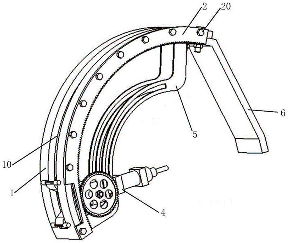
Referring to fig. 1, 2 and 3, fig. 1 is a schematic front structural view of an embodiment of the present application; FIG. 2 is a schematic diagram of a backside structure according to an embodiment of the present application; FIG. 3 is an exploded view of a pulley assembly and actuator assembly according to an embodiment of the present application; the embodiment of the application provides an annular track type actuator arrangement mechanism, which comprises an annular track 1, a planetary gear outer gear 2, a pulley assembly 3 and an actuator assembly 4, wherein a coaxial slot 10 is formed in the annular track 1; the slot 10 is opened from the outer arc surface of the annular track 1 to the inner arc surface of the annular track 1; the planet gear outer gear 2 is arc-shaped, is coaxially arranged with the annular track 1 and is fixed on one side of the annular track 1; the pulley component 3 comprises a connecting seat 30 and a limiting device 31, the connecting seat 30 is connected with the limiting device 31, the connecting seat 30 penetrates through the slot 10 from the outer arc surface of the annular track 1, and the limiting device 31 is lapped on the outer arc surface of the annular track 1; the actuator assembly 4 comprises a support 40, an actuator 41, a planetary gear internal gear 42 and a driving motor 43, wherein one end of the support 40 is connected with the connecting seat 30 of the pulley assembly 3; an actuator 41 provided at the other end of the support 40 opposite to the pulley assembly 3; the planet gear internal gear 42 is arranged on one side of the support 40 and is meshed with the planet gear external gear 2; the driving motor 43 is arranged on the other side of the support 40 opposite to the planetary gear internal gear 42, and the output end of the driving motor 43 penetrates through the support 40 and is connected with the planetary gear internal gear 42.
When multi-directional loading force loading needs to be carried out on automobile parts, the driving motor 43 is started, the output end of the driving motor 43 rotates to drive the planetary gear inner gear 42 connected with the driving motor to rotate, and the planetary gear inner gear 42 can rotate on the planetary gear outer gear 2 as the planetary gear inner gear 42 is meshed with the planetary gear outer gear 2; furthermore, the output end of the driving motor 43 is connected with the planet gear inner gear 42 through the support 40, so that the planet gear inner gear 42 rotates on the planet gear outer gear 2 and simultaneously drives the actuator 41 to rotate; because the connecting seat 30 of the pulley component 3 passes through the slot 10 from the outer arc surface of the annular track 1, the limiting device is lapped on the outer arc surface of the annular track 1, and the output end of the driving motor 43 drives the support 40 to move so as to drive the connecting seat 30 connected with the support 40 to move, the limiting device 31 can roll on the outer arc surface of the annular track 1, and the arrangement of the pulley component 3 ensures that the actuator 41 rotates along the annular track 1; at this time, the actuator 41 can realize the loading of force in any direction in a two-dimensional plane so as to realize the continuous adjustment of the loading direction of the actuator 41 and output the loading force in an unfixed direction for the automobile parts; when the automobile part is tested, the annular rotation of the actuator can be realized only by arranging one actuator, and the loading of force in any direction in a two-dimensional plane can be provided.
Optionally, a plurality of bolts 20 are arranged between the annular track 1 and the planetary gear outer gear 2 at intervals along an arc line; in order to fixedly mount the external planetary gear 2 on the annular orbit 1 and to tightly join the external planetary gear 2 and the annular orbit 1, the external planetary gear 2 and the annular orbit 1 do not have a gap therebetween, so that the actuator 41 does not have instability when outputting a load force to an automobile part during rotation, and therefore, a plurality of bolts are arranged at intervals along the arc line of the external planetary gear 2.
Optionally, the limiting devices 31 are arranged at two ends of the connecting seat 30; because the actuator 41 can apply different load forces to the automobile parts, the annular rail 1 can also receive the load force generated by the actuator 41 at the same time, and therefore the limiting devices 31 are arranged at the two ends of the connecting seat 30, so that the pulley assembly 3 can share the load force; and simultaneously, the actuator 41 can be ensured to be more stable when rotating along the circular track 1.
Optionally, the limiting device 31 is a fixed rod or a pulley; since the limiting device 31 can roll on the outer arc surface of the annular track 1, the limiting device 31 can be selected from a fixed rod or a pulley to realize that the limiting device 31 can roll on the outer arc surface of the annular track 1. It should be noted that the length of the fixed rod or the pulley needs to be greater than the width of the slot 10, so as to ensure that the fixed rod or the pulley can roll stably on the outer arc surface of the circular track 1 and cannot slide from the slot 10.
Optionally, the arrangement mechanism further comprises two guide members 5 arranged in parallel between the planetary gear internal gear 42 and the driving motor 43, and the actuator 41 is arranged between the two guide members 5. Since the actuator 41 applies different load forces to the automobile parts, the circular rail 1 is also subjected to the load force generated by the actuator 41, and in order to ensure that the arrangement mechanism works stably and is not easy to damage by the load force, the guide 5 can be used for sharing the load force, so that the arrangement mechanism can bear larger load force.
Referring to fig. 4, fig. 4 is an exploded view of the ring track, the guide member and the external planetary gear according to the embodiment of the present application, in which each guide member 5 includes a guide member first section 50, a guide member second section 51 and a guide member third section 52 in sequence; the first section 50 of the guide member is connected to the inner arc surface of one end of the circular track 1; the second section 51 of the guide piece is arc-shaped and is arranged coaxially with the annular track 1; the third section 52 of the guide part is connected to the inner cambered surface at the other end of the annular track 1; the arc length of the second guide segment 51 and the arc length of the circular track 1 are arc lengths of different radii at the same central angle.
The first section 50 of the guide part is connected to the inner arc surface at one end of the annular track 1, and the third section 52 of the guide part is connected to the inner arc surface at the other end of the annular track 1; can be connected with the inner cambered surfaces at the two ends of the annular track through fastening bolts; because the fastening bolt connection is used, if the guide piece 5 is damaged due to the loading force, only a new guide piece 5 needs to be replaced at the moment; it should be noted that the shapes of the first section 50 and the third section 52 of the guiding element are not limited to the shapes in the drawings, and other shapes are adopted to fix the inner arc surfaces of the two ends of the annular track and do not affect the rotation of the pulley assembly 3; the second section 51 of the guide piece is arc-shaped and is arranged coaxially with the annular track 1; in order to maintain the uniformity of movement of the actuator assembly 4 as it rotates between the slot 10 and the two guides 5.
Optionally, the second section 51 of the guiding member is provided with a guiding groove 510 along the arc direction; the guide slots 510 are provided to accommodate rotation of the actuator assembly, as described below.
Optionally, the actuator assembly 4 further includes a plurality of bearings 44 respectively disposed on the support 40 on the side of the driving motor 43 and on the side of the planetary gear inner gear 42, and the bearings 44 are inserted into the guide grooves 510 and can slide in the guide grooves 510. Since the actuator assembly 4 rotates between the two guide members 5, the bearing 44 on the actuator assembly 4 moves in the guide groove 510, so that the actuator 41 can be more stably and reliably rotated. Meanwhile, the arrangement mechanism is not easy to be damaged by the loading force of the actuator 41, and the arrangement mechanism can bear larger loading force.
Optionally, the output end of the driving motor 43 is a rotating shaft 430; when the driving motor 43 is activated, the rotating shaft 430 rotates to drive the planetary gear inner gear 42 connected with the rotating shaft to rotate.
According to the arrangement mechanism of the annular track type actuator, when multi-directional loading force is required to be loaded on automobile parts, the driving motor 43 is started, the output end of the driving motor 43 rotates to drive the inner gear 42 of the planetary gear connected with the driving motor to rotate, and the inner gear 42 of the planetary gear can rotate on the outer gear 2 of the planetary gear due to the fact that the inner gear 42 of the planetary gear is meshed with the outer gear 2 of the planetary gear, and the actuator 41 can be driven to rotate at the same time; because the connecting seat 30 of the pulley component 3 passes through the slot 10 from the outer arc surface of the annular track 1, and the limiting device is lapped on the outer arc surface of the annular track 1, the limiting device 31 can roll on the outer arc surface of the annular track 1; at the moment, the actuator 41 can realize the loading of force in any direction in a two-dimensional plane, the annular rotation of the actuator can be realized by only arranging one actuator, and the loading force in the unfixed direction can be output for automobile parts. Since the arrangement mechanism further comprises two guide members 5 arranged in parallel between the external planetary gear 2 and the driving motor 43, the actuator 41 is arranged between the two guide members 5, the second section 51 of the guide member 5 is provided with a guide groove 510 along the arc direction, and the bearing 44 is embedded in the guide groove 510 and can move in the guide groove 510; the actuator 41 can be more stable and reliable in rotation. Meanwhile, the arrangement mechanism is not easy to be damaged by the loading force of the actuator 41, and the arrangement mechanism can bear larger loading force.
The embodiment of the application also provides a test bench, which comprises the circular track type actuator arrangement mechanism shown in the figures 1 to 4 and a mounting bracket 6, wherein one end of the mounting bracket 6 is connected with one end of the circular track 1, and the other end of the mounting bracket is mounted on the test bench; the fatigue endurance test of the automobile parts can be realized by arranging the mechanism on the test bench through the annular track type actuator.
In the description of the present application, it should be noted that the terms "outer", "inner", and the like indicate orientations or positional relationships based on the orientations or positional relationships shown in the drawings, which are merely for convenience of describing the present application and simplifying the description, and do not indicate or imply that the referred device or element must have a specific orientation, be constructed in a specific orientation, and operate, and thus, should not be construed as limiting the present application. Unless expressly stated or limited otherwise, the terms "disposed," "connected," and "connected" are intended to be inclusive and mean, for example, that there may be a fixed connection, a removable connection, or an integral connection; can be mechanically or electrically connected; they may be connected directly or indirectly through intervening media, or they may be interconnected between two elements. The specific meaning of the above terms in the present application can be understood by those of ordinary skill in the art as appropriate.
It is noted that, in the present application, relational terms such as "first paragraph" and "second paragraph" and the like are used solely to distinguish one entity or action from another entity or action without necessarily requiring or implying any actual such relationship or order between such entities or actions. Also, the terms "comprises," "comprising," or any other variation thereof, are intended to cover a non-exclusive inclusion, such that a process, method, article, or apparatus that comprises a list of elements does not include only those elements but may include other elements not expressly listed or inherent to such process, method, article, or apparatus.
The above description is merely exemplary of the present application and is presented to enable those skilled in the art to understand and practice the present application. Various modifications to these embodiments will be readily apparent to those skilled in the art, and the generic principles defined herein may be applied to other embodiments without departing from the spirit or scope of the application. Thus, the present application is not intended to be limited to the embodiments shown herein but is to be accorded the widest scope consistent with the principles and novel features disclosed herein.