CN112007768A - Shower head with linear engine port communication - Google Patents
Shower head with linear engine port communication Download PDFInfo
- Publication number
- CN112007768A CN112007768A CN202010476627.XA CN202010476627A CN112007768A CN 112007768 A CN112007768 A CN 112007768A CN 202010476627 A CN202010476627 A CN 202010476627A CN 112007768 A CN112007768 A CN 112007768A
- Authority
- CN
- China
- Prior art keywords
- engine
- showerhead
- wall
- ports
- housing
- Prior art date
- Legal status (The legal status is an assumption and is not a legal conclusion. Google has not performed a legal analysis and makes no representation as to the accuracy of the status listed.)
- Granted
Links
Images

Classifications
-
- B—PERFORMING OPERATIONS; TRANSPORTING
- B05—SPRAYING OR ATOMISING IN GENERAL; APPLYING FLUENT MATERIALS TO SURFACES, IN GENERAL
- B05B—SPRAYING APPARATUS; ATOMISING APPARATUS; NOZZLES
- B05B1/00—Nozzles, spray heads or other outlets, with or without auxiliary devices such as valves, heating means
- B05B1/30—Nozzles, spray heads or other outlets, with or without auxiliary devices such as valves, heating means designed to control volume of flow, e.g. with adjustable passages
-
- B—PERFORMING OPERATIONS; TRANSPORTING
- B05—SPRAYING OR ATOMISING IN GENERAL; APPLYING FLUENT MATERIALS TO SURFACES, IN GENERAL
- B05B—SPRAYING APPARATUS; ATOMISING APPARATUS; NOZZLES
- B05B1/00—Nozzles, spray heads or other outlets, with or without auxiliary devices such as valves, heating means
- B05B1/14—Nozzles, spray heads or other outlets, with or without auxiliary devices such as valves, heating means with multiple outlet openings; with strainers in or outside the outlet opening
- B05B1/18—Roses; Shower heads
- B05B1/185—Roses; Shower heads characterised by their outlet element; Mounting arrangements therefor
-
- E—FIXED CONSTRUCTIONS
- E03—WATER SUPPLY; SEWERAGE
- E03C—DOMESTIC PLUMBING INSTALLATIONS FOR FRESH WATER OR WASTE WATER; SINKS
- E03C1/00—Domestic plumbing installations for fresh water or waste water; Sinks
- E03C1/02—Plumbing installations for fresh water
- E03C1/04—Water-basin installations specially adapted to wash-basins or baths
- E03C1/0408—Water installations especially for showers
- E03C1/0409—Shower handles
-
- B—PERFORMING OPERATIONS; TRANSPORTING
- B05—SPRAYING OR ATOMISING IN GENERAL; APPLYING FLUENT MATERIALS TO SURFACES, IN GENERAL
- B05B—SPRAYING APPARATUS; ATOMISING APPARATUS; NOZZLES
- B05B1/00—Nozzles, spray heads or other outlets, with or without auxiliary devices such as valves, heating means
- B05B1/14—Nozzles, spray heads or other outlets, with or without auxiliary devices such as valves, heating means with multiple outlet openings; with strainers in or outside the outlet opening
- B05B1/16—Nozzles, spray heads or other outlets, with or without auxiliary devices such as valves, heating means with multiple outlet openings; with strainers in or outside the outlet opening having selectively- effective outlets
- B05B1/1627—Nozzles, spray heads or other outlets, with or without auxiliary devices such as valves, heating means with multiple outlet openings; with strainers in or outside the outlet opening having selectively- effective outlets with a selecting mechanism comprising a gate valve, a sliding valve or a cock
- B05B1/1636—Nozzles, spray heads or other outlets, with or without auxiliary devices such as valves, heating means with multiple outlet openings; with strainers in or outside the outlet opening having selectively- effective outlets with a selecting mechanism comprising a gate valve, a sliding valve or a cock by relative rotative movement of the valve elements
-
- B—PERFORMING OPERATIONS; TRANSPORTING
- B05—SPRAYING OR ATOMISING IN GENERAL; APPLYING FLUENT MATERIALS TO SURFACES, IN GENERAL
- B05B—SPRAYING APPARATUS; ATOMISING APPARATUS; NOZZLES
- B05B1/00—Nozzles, spray heads or other outlets, with or without auxiliary devices such as valves, heating means
- B05B1/14—Nozzles, spray heads or other outlets, with or without auxiliary devices such as valves, heating means with multiple outlet openings; with strainers in or outside the outlet opening
- B05B1/16—Nozzles, spray heads or other outlets, with or without auxiliary devices such as valves, heating means with multiple outlet openings; with strainers in or outside the outlet opening having selectively- effective outlets
- B05B1/1627—Nozzles, spray heads or other outlets, with or without auxiliary devices such as valves, heating means with multiple outlet openings; with strainers in or outside the outlet opening having selectively- effective outlets with a selecting mechanism comprising a gate valve, a sliding valve or a cock
- B05B1/1663—Nozzles, spray heads or other outlets, with or without auxiliary devices such as valves, heating means with multiple outlet openings; with strainers in or outside the outlet opening having selectively- effective outlets with a selecting mechanism comprising a gate valve, a sliding valve or a cock by relative translatory movement of the valve elements
-
- B—PERFORMING OPERATIONS; TRANSPORTING
- B05—SPRAYING OR ATOMISING IN GENERAL; APPLYING FLUENT MATERIALS TO SURFACES, IN GENERAL
- B05B—SPRAYING APPARATUS; ATOMISING APPARATUS; NOZZLES
- B05B1/00—Nozzles, spray heads or other outlets, with or without auxiliary devices such as valves, heating means
- B05B1/14—Nozzles, spray heads or other outlets, with or without auxiliary devices such as valves, heating means with multiple outlet openings; with strainers in or outside the outlet opening
- B05B1/18—Roses; Shower heads
- B05B1/182—Roses; Shower heads characterised by their outlet openings or elements; Mounting arrangements therefor
-
- B—PERFORMING OPERATIONS; TRANSPORTING
- B05—SPRAYING OR ATOMISING IN GENERAL; APPLYING FLUENT MATERIALS TO SURFACES, IN GENERAL
- B05B—SPRAYING APPARATUS; ATOMISING APPARATUS; NOZZLES
- B05B1/00—Nozzles, spray heads or other outlets, with or without auxiliary devices such as valves, heating means
- B05B1/14—Nozzles, spray heads or other outlets, with or without auxiliary devices such as valves, heating means with multiple outlet openings; with strainers in or outside the outlet opening
- B05B1/18—Roses; Shower heads
- B05B1/182—Roses; Shower heads characterised by their outlet openings or elements; Mounting arrangements therefor
- B05B1/1821—Roses; Shower heads characterised by their outlet openings or elements; Mounting arrangements therefor the outlet openings arranged in plural groups or rows
- B05B1/1825—Roses; Shower heads characterised by their outlet openings or elements; Mounting arrangements therefor the outlet openings arranged in plural groups or rows with three or more dissimilar groups or rows
-
- E—FIXED CONSTRUCTIONS
- E03—WATER SUPPLY; SEWERAGE
- E03C—DOMESTIC PLUMBING INSTALLATIONS FOR FRESH WATER OR WASTE WATER; SINKS
- E03C1/00—Domestic plumbing installations for fresh water or waste water; Sinks
- E03C1/02—Plumbing installations for fresh water
- E03C1/04—Water-basin installations specially adapted to wash-basins or baths
- E03C1/0404—Constructional or functional features of the spout
- E03C1/0405—Constructional or functional features of the spout enabling multiple spray patterns
-
- B—PERFORMING OPERATIONS; TRANSPORTING
- B05—SPRAYING OR ATOMISING IN GENERAL; APPLYING FLUENT MATERIALS TO SURFACES, IN GENERAL
- B05B—SPRAYING APPARATUS; ATOMISING APPARATUS; NOZZLES
- B05B1/00—Nozzles, spray heads or other outlets, with or without auxiliary devices such as valves, heating means
- B05B1/14—Nozzles, spray heads or other outlets, with or without auxiliary devices such as valves, heating means with multiple outlet openings; with strainers in or outside the outlet opening
- B05B1/18—Roses; Shower heads
- B05B1/182—Roses; Shower heads characterised by their outlet openings or elements; Mounting arrangements therefor
- B05B1/1821—Roses; Shower heads characterised by their outlet openings or elements; Mounting arrangements therefor the outlet openings arranged in plural groups or rows
- B05B1/1823—Concentric or coaxial groups
-
- B—PERFORMING OPERATIONS; TRANSPORTING
- B05—SPRAYING OR ATOMISING IN GENERAL; APPLYING FLUENT MATERIALS TO SURFACES, IN GENERAL
- B05B—SPRAYING APPARATUS; ATOMISING APPARATUS; NOZZLES
- B05B1/00—Nozzles, spray heads or other outlets, with or without auxiliary devices such as valves, heating means
- B05B1/14—Nozzles, spray heads or other outlets, with or without auxiliary devices such as valves, heating means with multiple outlet openings; with strainers in or outside the outlet opening
- B05B1/18—Roses; Shower heads
- B05B1/188—Roses; Shower heads with user-actuated controlling members
- B05B1/189—Roses; Shower heads with user-actuated controlling members actuated by a rotating movement
-
- B—PERFORMING OPERATIONS; TRANSPORTING
- B05—SPRAYING OR ATOMISING IN GENERAL; APPLYING FLUENT MATERIALS TO SURFACES, IN GENERAL
- B05B—SPRAYING APPARATUS; ATOMISING APPARATUS; NOZZLES
- B05B1/00—Nozzles, spray heads or other outlets, with or without auxiliary devices such as valves, heating means
- B05B1/14—Nozzles, spray heads or other outlets, with or without auxiliary devices such as valves, heating means with multiple outlet openings; with strainers in or outside the outlet opening
- B05B1/18—Roses; Shower heads
- B05B1/188—Roses; Shower heads with user-actuated controlling members
- B05B1/1896—Roses; Shower heads with user-actuated controlling members located in or on the housing
-
- B—PERFORMING OPERATIONS; TRANSPORTING
- B05—SPRAYING OR ATOMISING IN GENERAL; APPLYING FLUENT MATERIALS TO SURFACES, IN GENERAL
- B05B—SPRAYING APPARATUS; ATOMISING APPARATUS; NOZZLES
- B05B1/00—Nozzles, spray heads or other outlets, with or without auxiliary devices such as valves, heating means
- B05B1/30—Nozzles, spray heads or other outlets, with or without auxiliary devices such as valves, heating means designed to control volume of flow, e.g. with adjustable passages
- B05B1/3026—Gate valves; Sliding valves; Cocks
Landscapes
- Health & Medical Sciences (AREA)
- Life Sciences & Earth Sciences (AREA)
- Engineering & Computer Science (AREA)
- Hydrology & Water Resources (AREA)
- Public Health (AREA)
- Water Supply & Treatment (AREA)
- Nozzles (AREA)
Abstract
提供了一种具有直线型引擎端口连通的淋浴头。淋浴头可包括限定流体入口通路的壳体以及可旋转地安装到壳体的引擎。引擎可包括被限定在引擎的侧壁内的一系列端口。所述一系列端口可与引擎内限定的不同流动通路相关联。引擎相对于壳体的旋转可使流体入口通路与所述一系列端口中的一个选择性地对准。

A shower head with linear engine port communication is provided. The showerhead may include a housing defining a fluid inlet passage and an engine rotatably mounted to the housing. The engine may include a series of ports defined within the sidewall of the engine. The series of ports may be associated with different flow paths defined within the engine. Rotation of the engine relative to the housing may selectively align the fluid inlet passage with one of the series of ports.
Description
技术领域technical field
本公开一般地涉及淋浴头,且更具体地涉及具有直线型引擎端口连通(porting)的淋浴头。The present disclosure relates generally to showerheads, and more particularly to showerheads having linear engine porting.
背景技术Background technique
淋浴头一般地用于将水从供水装置引导到用户、动物或物体身上,诸如用于个人卫生目的和/或清洗目的。许多淋浴头包括允许用户选择许多种淋浴头操作模式中的一种的引擎或结构,每种操作模式喷出具有不同特性的水流。例如,一些淋浴头可包括喷出脉动水流的按摩模式、将水喷出为相对小的型式的集中模式、以及以稳定且柔和的喷洒型式喷出水的喷淋模式。Shower heads are typically used to direct water from a water supply to a user, animal or object, such as for personal hygiene purposes and/or cleaning purposes. Many showerheads include an engine or structure that allows the user to select one of a number of showerhead operating modes, each of which sprays a stream of water with different characteristics. For example, some showerheads may include a massage mode that sprays a pulsating stream of water, a concentrated mode that sprays water in relatively small patterns, and a shower mode that sprays water in a steady and gentle spray pattern.
淋浴头通常包括入口水路径,入口水路径延伸穿过淋浴头的壳体或手柄并且然后以大约90度转弯通过形成在引擎的背表面中的一系列孔口或端口中的一个而进入淋浴头的引擎。水路径通常需要具有某种形状因子的淋浴头,该形状因子具有相对实质性的横截面以容纳水路径。由于水路径中的转弯,所以该水路径还可降低淋浴头内的流体压力。The showerhead typically includes an inlet water path that extends through the housing or handle of the showerhead and then enters the showerhead through one of a series of apertures or ports formed in the back surface of the engine at an approximately 90-degree turn engine. The water path typically requires a shower head with some form factor that has a relatively substantial cross-section to accommodate the water path. The water path may also reduce fluid pressure within the showerhead due to turns in the water path.
因此,期望提供一种改进的淋浴头,其至少部分地解决上文所描述的问题和/或更一般地提供对现有布置的改进或替代。Accordingly, it would be desirable to provide an improved showerhead that at least partially addresses the problems described above and/or more generally provides an improvement or alternative to existing arrangements.
发明内容SUMMARY OF THE INVENTION
本公开一般地提供了一种具有代替传统淋浴头引擎中的90度水通路的直线型引擎端口连通的淋浴头。一般地,水通过引擎的侧部(诸如,通过侧壁)进入,而不是通过引擎的背部进入。引擎的侧部可包括与引擎内的不同的流动通路相关联的一系列孔口或端口,其中这些不同的流动通路对应于淋浴头的不同的操作模式。所述一系列孔口或端口被定位(诸如,水平地对准并沿着引擎的侧部间隔开)成使得引擎相对于淋浴头的壳体的旋转使由淋浴头壳体(例如,淋浴头的手柄)限定的流体入口通路与孔口或端口中的一个选择性地对准。淋浴头可包括卡环,该卡环被定位或接收在引擎和壳体之间(诸如,被接收在对应的环形沟槽中),以将引擎可旋转地安装到壳体。The present disclosure generally provides a showerhead with straight engine port communication that replaces the 90 degree water passage in conventional showerhead engines. Typically, water enters through the sides of the engine (such as through the sidewalls) rather than through the back of the engine. The sides of the engine may include a series of orifices or ports associated with different flow passages within the engine, wherein the different flow passages correspond to different modes of operation of the showerhead. The series of orifices or ports are positioned (such as aligned horizontally and spaced along the sides of the engine) such that rotation of the engine relative to the housing of the showerhead causes the The fluid inlet passage defined by the handle) is selectively aligned with one of the orifices or ports. The showerhead may include a snap ring positioned or received between the engine and the housing (such as in a corresponding annular groove) to rotatably mount the engine to the housing.
根据本公开的一个方面,提供了一种淋浴头。该淋浴头可包括限定流体入口通路的壳体以及可旋转地附接到壳体的引擎。引擎可包括通过引擎的外侧壁开放的一系列端口,并且所述一系列端口可与被限定在引擎内的不同的流动通路相关联。引擎可相对于壳体旋转,以使流体入口通路与所述一系列端口中的一个或多个端口选择性地对准。According to one aspect of the present disclosure, a shower head is provided. The showerhead may include a housing defining a fluid inlet passage and an engine rotatably attached to the housing. The engine may include a series of ports open through the outer sidewall of the engine, and the series of ports may be associated with different flow passages defined within the engine. The engine is rotatable relative to the housing to selectively align the fluid inlet passage with one or more of the series of ports.
附加的特征在下面的描述中被部分地阐述,并且对于本领域技术人员而言在查阅说明书和附图时将变得显而易见或者可通过实践所公开的主题而获悉。通过参考形成本公开的一部分的说明书和附图的其余部分,可实现对本公开的本质和优点的进一步理解。Additional features are set forth in part in the following description, and will become apparent to those skilled in the art upon review of the specification and drawings, or may be learned by practice of the disclosed subject matter. A further understanding of the nature and advantages of the present disclosure may be realized by reference to the remaining portions of the specification and drawings which form a part of this disclosure.
本领域技术人员将理解,本公开的各个方面和特征中的每一者可有利地在一些情况下单独地使用,或者在其他情况下与本公开的其他方面和特征结合使用。因此,可以单独地或与其他方面和特征结合来要求保护各个方面。因此,本公开本质上仅是示例性的,且绝不旨在限制要求保护的发明或其应用或用途。将理解的是,在不脱离本公开的精神和范围的情况下,可做出结构和/或逻辑改变。Those skilled in the art will appreciate that each of the various aspects and features of this disclosure may be advantageously used in some cases alone or in other cases in combination with other aspects and features of this disclosure. Accordingly, various aspects may be claimed alone or in combination with other aspects and features. Accordingly, this disclosure is merely exemplary in nature and is in no way intended to limit the claimed invention or its application or uses. It will be understood that structural and/or logical changes may be made without departing from the spirit and scope of the present disclosure.
本公开以各种详细程度被阐述,并且不旨在通过在本发明内容中包括抑或不包括元件、部件等来对要求保护的主题的范围进行限制。在某些情况下,可能已经省略了对于理解本公开不必要的或使其他细节难以理解的细节。此外,为了清楚起见,当某些特征对于本领域技术人员而言将是显而易见时,将不会讨论对它们的详细描述,以免模糊本公开的描述。要求保护的主题不一定限于本文中所图示的布置,其中本公开的范围仅由所附权利要求限定。This disclosure is set forth in various levels of detail and is not intended to limit the scope of the claimed subject matter by the inclusion or exclusion of elements, components, etc. in this summary. In some instances, details which are unnecessary to an understanding of the present disclosure or which obscure other details may have been omitted. Furthermore, for the sake of clarity, when certain features would be apparent to those skilled in the art, their detailed description will not be discussed so as not to obscure the description of the present disclosure. The claimed subject matter is not necessarily limited to the arrangements illustrated herein, with the scope of the present disclosure being limited only by the appended claims.
附图说明Description of drawings
将参考以下附图来更充分地理解该描述,在附图中,部件可能未按比例绘制,这些部件被作为本文中所描述的淋浴头的各种实施例呈现并且不应被解释为对淋浴头的范围的完整描绘。This description will be more fully understood with reference to the following drawings in which components, which may not be drawn to scale, are presented as various embodiments of the showerheads described herein and should not be construed as a Complete depiction of the scope of the head.
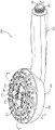
图1是根据本公开的一些示例的淋浴头的等距视图。1 is an isometric view of a shower head according to some examples of the present disclosure.
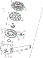
图2是根据本公开的一些示例的图1的淋浴头的前视分解图。2 is a front exploded view of the showerhead of FIG. 1 according to some examples of the present disclosure.
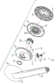
图3是根据本公开的一些示例的图1的淋浴头的后视分解图。3 is a rear exploded view of the showerhead of FIG. 1 according to some examples of the present disclosure.
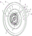
图4是根据本公开的一些示例的图1的淋浴头的引擎的等距视图,其中出于图示的目的喷嘴板被移除。4 is an isometric view of the engine of the showerhead of FIG. 1 with the nozzle plate removed for illustration purposes, according to some examples of the present disclosure.
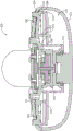
图5是根据本公开的一些示例的沿着图1中的线5-5截取的图1的淋浴头的横截面图。5 is a cross-sectional view of the showerhead of FIG. 1 taken along line 5-5 in FIG. 1, according to some examples of the present disclosure.
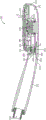
图6是根据本公开的一些示例的沿着图1中的线6-6截取的图1的淋浴头的另一个横截面图。6 is another cross-sectional view of the showerhead of FIG. 1 taken along line 6-6 in FIG. 1, according to some examples of the present disclosure.
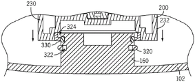
图7是根据本公开的一些示例的示出将引擎附接在淋浴头内的第一步骤的横截面图。7 is a cross-sectional view illustrating a first step of attaching an engine within a showerhead, according to some examples of the present disclosure.
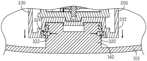
图8是根据本公开的一些示例的示出将引擎附接在淋浴头内的第二步骤的横截面图。8 is a cross-sectional view illustrating a second step of attaching an engine within a showerhead, according to some examples of the present disclosure.
图9是根据本公开的一些示例的示出引擎在淋浴头内完全附接的横截面图。9 is a cross-sectional view showing the engine fully attached within the showerhead, according to some examples of the present disclosure.
具体实施方式Detailed ways
提供了一种包括直线型引擎端口连通的淋浴头。具体地说,流体(例如,水)通过引擎的侧部而不是背部进入引擎。为了改变淋浴头的操作模式,用户可以相对于淋浴头的壳体旋转引擎,以使形成在引擎的侧部中的一系列孔口或端口中的一个与由壳体限定的流体入口通路选择性地对准。每个孔口或端口可与淋浴头的不同的操作模式相关联。A shower head is provided that includes linear engine port communication. Specifically, fluid (eg, water) enters the engine through the sides of the engine rather than the back. To change the mode of operation of the showerhead, the user can rotate the engine relative to the housing of the showerhead to select one of a series of apertures or ports formed in the side of the engine with the fluid inlet passage defined by the housing ground alignment. Each orifice or port may be associated with a different mode of operation of the showerhead.
与传统的多模式淋浴头相比,本文中所描述的直线型引擎端口连通可允许淋浴头具有减小的形状因子(诸如,更薄),这至少部分地是由于水通过引擎的侧部(例如,侧表面或侧壁)端口连通而不是通过引擎的后部(例如,后表面或背壁)端口连通。由于流动路径中的改进的流体动力学,直线型引擎端口连通可增加水离开淋浴头的力。例如,通过将水通过引擎的侧部而不是其背部端口连通,从流动路径移除了在传统淋浴头中发现的90度或类似转弯的减压。The straight-line engine port communication described herein may allow the shower head to have a reduced form factor (such as being thinner) compared to traditional multi-mode showerheads, at least in part due to water passing through the sides of the engine ( For example, side surface or sidewall) port communication rather than through the rear of the engine (eg, rear surface or back wall) port communication. The straight engine port communication can increase the force with which the water leaves the shower head due to improved fluid dynamics in the flow path. For example, by communicating the water through the side of the engine rather than its back port, the 90 degree or similar turn relief found in conventional shower heads is removed from the flow path.
淋浴头引擎限定淋浴头的各种操作模式。为了设定淋浴头的操作模式,用户可以相对于壳体旋转引擎,以使流体入口通路与形成在引擎的侧部中的与淋浴头的期望的操作模式相关联的一系列孔口或端口中的一个选择性地对准。引擎可以以各种方式附接到淋浴头的壳体。在一些示例中,引擎可经由卡环而不是通过紧固件附接到壳体,以便于将引擎附接到壳体,诸如提供将引擎附接到壳体的成本有效的过程。在其他示例中,引擎可经由一个或多个紧固件或以其他方式附接到壳体。The showerhead engine defines various operating modes of the showerhead. To set the operating mode of the showerhead, the user can rotate the engine relative to the housing so that the fluid inlet passages are in a series of orifices or ports formed in the side of the engine associated with the desired operating mode of the showerhead A selectively aligned. The engine can be attached to the housing of the shower head in various ways. In some examples, the engine may be attached to the housing via a snap ring rather than by fasteners to facilitate attaching the engine to the housing, such as to provide a cost-effective process for attaching the engine to the housing. In other examples, the engine may be attached to the housing via one or more fasteners or otherwise.
参考图1至图3和图6,淋浴头100可包括壳体102,该壳体限定淋浴头100的流体入口通路130。流体入口通路130从诸如软管、J形管等的流体源接收流体(例如,水),并且将流体运输到淋浴头100的引擎200。为了将淋浴头100连接到流体源,壳体102可包括螺纹132或另一种连接特征。Referring to FIGS. 1-3 and 6 , the
淋浴头100的壳体102可包括喷头106,引擎200可旋转地附接到该喷头。如图2中所图示的,喷头106可限定用于接收引擎200的内部空腔142。例如,喷头106可以是弓形的(诸如,碗形),其中侧壁140从后壁152延伸以限定内部空腔142。面板104可附接到侧壁140的终端边缘或边沿150以围封内部空腔142(见图5)。如图2中所示,凸台160可从喷头106的后壁152延伸到内部空腔142中,以用于将引擎200附接到壳体102。凸台160可具有圆形横截面。The
如在图1至图3和图6中所图示的,壳体102可限定从喷头106延伸的臂120。臂120可以是长形构件,其包括用于连接到流体源的连接特征,诸如螺纹132。如图6中所图示的,流体入口通路130可在臂120的长度内且沿着臂120的长度延伸。淋浴头100可以是手持式淋浴头(例如,被构造成用于附接到软管)或者固定或壁装式淋浴头(例如,被构造成固定地附接到流体源)。在淋浴头100是手持式淋浴头的构型中,臂120可具有被构造成舒适地握在用户手中的形状(诸如,图1至图3和图6中所图示的形状),并且可被认为是手柄。As illustrated in FIGS. 1-3 and 6 , the
参考图1至图3,淋浴头100可包括多个出口喷嘴170。可将出口喷嘴170布置成一个或多个集合或组,并且每个集合或组可与淋浴头100的不同的操作模式相关联。例如,第一喷嘴组172可与淋浴头100的第一操作模式相关联,第二喷嘴组174可与淋浴头100的第二操作模式相关联,第三喷嘴组176可与第三操作模式相关联等等。淋浴头100的操作模式可包括全身模式、按摩模式、雾化模式、集中模式以及其他模式。淋浴头100可包括模式选择器,以供用户进行操纵以在不同的操作模式之间切换淋浴头100。Referring to FIGS. 1-3 , the
出口喷嘴170可以是具有被限定为穿过出口喷嘴的内腔的凸出的突起、被限定在面板104自身内的孔口、或不同的构型。限定出口喷嘴170的内腔和/或孔口可被构造成为淋浴头100提供流体流特性。出口喷嘴170可形成为面板104的一部分或形成为淋浴头100的另一个元件的一部分。The
参考图1至图6,引擎200被定位在喷头106的内部空腔142内。引擎200相对于喷头106的旋转位置决定淋浴头100的操作模式。换句话说,取决于引擎200相对于喷头106的位置,引擎200将流体从流体入口通路130引导到出口喷嘴170的不同子集或组。Referring to FIGS. 1-6 , the
引擎200一般地限定用于淋浴头100的每种操作模式的不同流动通路。例如,引擎200可限定与淋浴头100的第一操作模式相关联的第一流动通路210、与淋浴头100的第二操作模式相关联的第二流动通路212、与淋浴头100的第三操作模式相关联的第三流动通路214等等。
引擎200相对于壳体102的旋转位置决定被限定在引擎200内的哪条流动通路有效。例如,引擎200可被定位在第一位置中,以使流体入口通路130与第一流动通路210对准并将淋浴头100置于第一操作模式中。引擎200可被定位在第二位置中,以使流体入口通路130与第二流动通路212对准并将淋浴头100置于第二操作模式中。引擎200可被定位在第三位置中,以使流体入口通路130与第三流动通路214对准并将淋浴头100置于第三操作模式中,等等。用户可使引擎200在各个位置之间旋转,以允许用户容易地选择淋浴头100的期望的操作模式。The rotational position of the
如本文中所描述的,引擎200可被构造成经由直线型端口连通从流体入口通路130接收流体。例如,流体通过引擎200的与流体入口通路130基本上成一直线的侧部部分进入,而不是流体通过高度数的转弯(诸如,90度转弯)从流体入口通路130流到引擎200。换句话说,流体通过引擎200的侧部部分(例如,侧壁)端口连通,而不是通过引擎的后部部分(例如,背壁)端口连通。与传统设计相比,该直线型端口连通特性提供了改进的通过淋浴头100的流体动力学,这可增加流体离开淋浴头100的力。与其中流体通过引擎的背部端口连通的传统设计相比,该直线型端口连通特性允许淋浴头100具有减小的形状因子,诸如更薄的喷头。As described herein,
引擎200可包括各种部件。例如,如图2至图6中所示,引擎200可包括流动控制板230。流动控制板230可由基壁232和以一定角度从基壁232延伸以在引擎200内限定不同的流动通路的至少一个壁限定。基壁232可以是如图所示的圆形,或者可包括提供引擎200的一个或多个流动或附接特性的其他合适的构型。在一些示例中,引擎200包括多个壁以限定引擎200内的不同流动通路。例如,引擎200可包括:第一壁240,所述第一壁与基壁232一起限定第一流动通路210;第二壁242,所述第二壁与基壁232和第一壁240一起限定第二流动通路212;第三壁244,所述第三壁与基壁232和第二壁242一起限定第三流动通路214,等等。
参考图4,多个或一系列端口250可被限定在引擎200的外侧壁234内,以提供从流体入口通路130到引擎200的直线型端口连通。所述一系列端口250可与被限定在引擎200内的不同的流动通路相关联。例如,第一端口252可与第一流动通路210流体连通,第二端口254可与第二流动通路212流体连通,且第三端口256可与第三流动通路214流体连通。端口250可被定位成便于在引擎200在其各个位置之间切换时从流体入口通路130到引擎200的直线型端口连通。如图3中所图示的,引擎200的外侧壁234可被定位在引擎200的前表面和后表面之间。Referring to FIG. 4 , a plurality or series of
如图4中所示,端口250可水平地对准(诸如,在平面中),并且沿着引擎200的外侧壁234间隔开。如下文所详述的,这种对准和间隔可便于从流体入口通路130穿过引擎200的直线型端口连通。例如,端口250中的每一个在该端口被选择成用于操作时可限定引擎200入口流动方向A(见图6)(例如,当淋浴头100处于第一操作模式时,选择第一端口252,当淋浴头100处于第二操作模式时,选择第二端口254等)。入口流动方向A可基本上平行于流体入口通路130,以提供从流体入口通路130穿过引擎200的直线型端口连通。As shown in FIG. 4 , the
外侧壁234可流体地密封到臂120,以确保引擎200和臂120之间的不透流体的对接。参考图2、图3和图6,淋浴头100可包括密封结构350,以将流体入口通路130与选定端口250流体地联接。如图6中所图示的,密封结构350可被接收在凹部351内,该凹部由壳体102在臂120和喷头106的相交处限定。密封结构350可包括:密封件或密封构件352,所述密封件或密封构件可相对于引擎200沿径向方向移动;以及弹簧354,所述弹簧使密封件352偏压抵靠引擎200。弹簧354可坐靠臂120(例如,抵靠臂120的内肩部355),并且密封件352可通过弹簧354偏压抵靠引擎200的外侧壁234。密封件352可限定穿过其中的单个孔口356(见图2),以将流体入口通路130和选定端口250流体地连接。如图6中所图示的,流体可从流体入口通路130通过弹簧354的内孔,通过密封件352的孔口356,并流到引擎200的选定端口中。The
为了便于引擎200相对于壳体102的旋转,引擎200的外侧壁234和密封件352可包括对应的弯曲表面。例如,如图3中所图示的,引擎200的外侧壁234可包括凸形外表面235,并且密封件352可包括用于接合外侧壁234的外表面235的凹形外表面353。密封件352经由弹簧354的运动可便于引擎200相对于喷头106的旋转,同时维持流体入口通路130和引擎200的选定端口250之间的不透流体的密封。在引擎200的旋转期间,引擎200的外侧壁234的外表面235可沿着密封件352的外表面353滑动,同时维持其间的不透流体的密封。To facilitate rotation of
端口250可延伸穿过引擎200的各个内壁,以将相应的端口250流体地联接到其相应的流动通路210、212、214。端口250中的每一个可通过引擎200的外侧壁234开放,并且可与密封件352中的孔口356选择性地对准,以流体地联接到流体入口通路130。所述端口中的一个端口(例如,第一端口252)可穿过引擎200的内壁240、242,以将流体入口通路130与引擎200的第一流动通路210流体地联接。所述端口中的另一个端口(例如,第二端口254)可穿过引擎200的内壁242但不穿过内壁240,以将流体入口通路130与引擎200的第二流动通路212流体地联接。所述端口中的另外一个端口(例如,第三端口256)可穿过引擎200的外侧壁234但不穿过内壁240、242,以将流体入口通路130与引擎200的第三流动通路214流体地联接。在这样的示例中,引擎200可包括被限定在各个壁之间的一个或多个导管,以将端口与引擎200的各个流动通路连接。例如,第一导管262可被限定在第一内壁240、第二内壁242和第三壁244之间,以将第一端口252与引擎200的第一流动通路210联接。类似地,第二导管264可被限定在第二内壁242和第三壁244之间,以将第二端口254与引擎200的第二流动通路212联接。第三端口256可直接通入引擎200的第三流动通路214中,且因此可省略用于第三端口256的导管。
引擎200可包括按摩模式组件300,该按摩模式组件被定位在第一流动通路210内以限定淋浴头100的按摩模式。按摩模式组件300可被构造成将一组出口喷嘴170(例如,第一喷嘴组172)与第一流动通路210交替地流体连接和断开连接以提供脉动或间歇的喷洒型式。按摩模式组件300可包括许多构型,包括但不限于美国公开号2016/0318046A1中所描述的那些构型,所述公开的公开内容通过引用以其整体并入本文。
参考图2、图4和图5,引擎200可包括喷嘴板280,该喷嘴板密封抵靠流动控制板230以限定引擎200的不同流动通路。例如,喷嘴板280可密封抵靠流动控制板230的第一壁240、第二壁242和第三壁244,以限定第一流动通路210、第二流动通路212和第三流动通路214(见图4和图5)。在所示的图示性示例中,喷嘴板280包括基部282和从基部282延伸的多个壁284(见图5)。所述多个壁284可被成形成用于与流动控制板230的壁234对应地接合,不过构想其他构型,包括其中基部282自身密封抵靠流动控制板230的侧壁234的示例。Referring to FIGS. 2 , 4 and 5 , the
出口喷嘴170可由喷嘴板280形成。出口喷嘴170可从喷嘴板280的基部282延伸。在这样的示例中,面板104可包括对应的孔口290,从而允许至少部分地通过所述孔口接收出口喷嘴170。如图6中最佳所见,出口喷嘴170可限定淋浴头100的出口流动方向B。在这样的示例中,出口流动方向B可与引擎200的入口流动方向A成不平行的角度。例如,出口流动方向B可与入口流动方向A成正交的角度,不过构想了其他不平行的角度。The
图7至图9是图示联接到壳体102的引擎200的示例的横截面图。参考图7至图9,引擎200可被可旋转地安装到喷头106。例如,流动控制板230的基壁232可被可旋转地联接到喷头106,诸如被可旋转地联接到从壳体102突出的凸台160。在这样的示例中,引擎200相对于喷头106的旋转可使流体入口通路130与所述一系列端口250中的一个选择性地对准。例如,引擎200到第一旋转位置的旋转可使流体入口通路130与第一端口252对准,于是流体从流体入口通路130流入引擎200的第一流动通路210中,以致动淋浴头100的第一操作模式。类似地,引擎200到第二旋转位置的旋转可使流体入口通路130与第二端口254对准,于是流体从流体入口通路130流入引擎200的第二流动通路212中,以致动淋浴头100的第二操作模式。引擎200到第三旋转位置的旋转可使流体入口通路130与第三端口256对准,于是流体从流体入口通路130流入引擎200的第三流动通路214中,以致动淋浴头100的第三操作模式。FIGS. 7-9 are cross-sectional views illustrating examples of the
引擎200可以以各种方式可旋转地安装到喷头106。例如,引擎200可经由卡环320可旋转地联接到喷头106。卡环320可定位在喷头106和引擎200之间,以将引擎200可旋转地安装到喷头106。如图6至图8中所示,喷头106可限定第一环形沟槽322,诸如被限定在凸台160中的第一环形沟槽322。引擎200可限定第二环形沟槽324,诸如被限定在基壁232中的第二环形沟槽324。在这样的示例中,卡环320可被接收在喷头106的第一环形沟槽322和引擎200的第二环形沟槽324内,以将引擎200附接到喷头106。一旦引擎200联接到喷头106,卡环320就可至少部分地被定位在第一环形沟槽322和第二环形沟槽324中的每一者内。卡环320可保持在喷头106上,诸如坐落在喷头106的第一环形沟槽322内。
卡环320可被构造成便于引擎200与喷头106的附接。例如,可对卡环320进行倒角以便于卡环320在引擎200与喷头106的附接期间的变形。引擎200可包括倒角边缘330以用于与倒角的卡环320对应地接合。例如,当引擎200被按压到喷头106的凸台160上时,引擎200的倒角边缘330可接合卡环320的倒角部分(见图7)。在这样的示例中,引擎200在喷头106内的进一步插入可将卡环320移动到第一环形沟槽322中,诸如将卡环320压缩到第一环形沟槽322中(见图8),以允许引擎200坐落到凸台160上。如图9中所示,一旦卡环320被充分压缩以允许引擎200进一步坐落到凸台160上,引擎200在喷头106内的进一步插入就可允许卡环320卡入引擎200的第二环形沟槽324中,以将引擎200联接到喷头106。例如,当第二环形沟槽324与第一环形沟槽322对准时,引擎200在喷头106内的进一步插入可允许卡环320向外膨胀到形成在引擎200中的第二环形沟槽324中。一旦卡环320被定位在第一环形沟槽322和第二环形沟槽324内,引擎200就可绕凸台160且相对于喷头106旋转以使流体入口通路130与所述一系列端口250中的一个选择性地对准,以准许流体从流体入口通路130流到出口喷嘴170。The
图6至图8图示了使用卡环320将引擎200附接到喷头106的一个示例。然而,将了解的是,构想了其他构型。例如,相反的构型是合适的,其中引擎200在喷头106的空腔内的插入使卡环320膨胀到第一环形沟槽322中。在这样的示例中,一旦第二环形沟槽324与第一环形沟槽322对准以将引擎200附接到喷头106,引擎200在喷头106内的进一步插入就可允许卡环320向内卡入形成在引擎200中的第二环形沟槽324中。附加地或替代地,可使用紧固件、热或声波焊接、粘合剂等将引擎附接到壳体。FIGS. 6-8 illustrate one example of attaching the
通过示例的方式给出所有相对的和方向参考(包括:上、下、向上、向下、左、右、向左、向右、顶部、底部、侧部、上方、下方、前、中间、后、竖直、水平等等)以帮助读者理解本文中所描述的示例。它们不应被解读为特别是对于位置、取向或用途的要求或限制,除非在权利要求中具体地阐述。连接参考(例如,附接、联接、连接、联结等)将被广泛地解释,并且可在元件的连接之间包括中间构件以及在元件之间包括相对运动。因而,连接参考不一定地推断出两个元件被直接且以彼此固定的关系连接,除非在权利要求中具体地阐述。All relative and directional references are given by way of example (including: up, down, up, down, left, right, left, right, top, bottom, side, above, below, front, center, back , vertical, horizontal, etc.) to help the reader understand the examples described herein. They should not be construed as requirements or limitations, particularly with respect to position, orientation, or use, unless specifically recited in the claims. Connection references (eg, attached, coupled, connected, coupled, etc.) are to be construed broadly and may include intermediate members between connections of elements and relative movement between elements. Thus, a connecting reference does not necessarily infer that two elements are connected directly and in a fixed relationship to each other, unless specifically recited in a claim.
本公开通过示例而非限制的方式教导。因此,以上描述中包含的或附图中所示的内容应以图示性而非限制性的意义上解释。所附权利要求旨在涵盖本文中所描述的所有一般和特定特征以及本方法和系统的范围的所有陈述,在语言方面,可以说这些特征和陈述落在所附权利要求中。The present disclosure teaches by way of example and not limitation. Accordingly, what is contained in the above description or shown in the accompanying drawings is to be interpreted in an illustrative rather than a restrictive sense. The appended claims are intended to cover all general and specific features described herein, as well as all statements of the scope of the present method and system, which language may be said to fall within the appended claims.
Claims (20)
Applications Claiming Priority (2)
| Application Number | Priority Date | Filing Date | Title |
|---|---|---|---|
| US201962854202P | 2019-05-29 | 2019-05-29 | |
| US62/854202 | 2019-05-29 |
Publications (2)
| Publication Number | Publication Date |
|---|---|
| CN112007768A true CN112007768A (en) | 2020-12-01 |
| CN112007768B CN112007768B (en) | 2023-01-03 |
Family
ID=73507117
Family Applications (1)
| Application Number | Title | Priority Date | Filing Date |
|---|---|---|---|
| CN202010476627.XA Active CN112007768B (en) | 2019-05-29 | 2020-05-29 | Shower head with linear engine port communication |
Country Status (3)
| Country | Link |
|---|---|
| US (1) | US11813622B2 (en) |
| CN (1) | CN112007768B (en) |
| CA (1) | CA3080909C (en) |
Families Citing this family (4)
| Publication number | Priority date | Publication date | Assignee | Title |
|---|---|---|---|---|
| USD935557S1 (en) * | 2021-06-23 | 2021-11-09 | Xiamen Galenpoo Kitchen & Bathroom Technology Co., Ltd. | Shower head |
| USD931411S1 (en) * | 2021-07-15 | 2021-09-21 | Xiamen Galenpoo Kitchen&Bathroom Technology Co., Ltd. | Shower head |
| US12478989B2 (en) | 2022-04-29 | 2025-11-25 | Brasstech, Inc. | Showerhead |
| CN121419835A (en) * | 2023-06-30 | 2026-01-27 | 德尔塔阀门公司 | Handheld shower head including brush section |
Citations (16)
| Publication number | Priority date | Publication date | Assignee | Title |
|---|---|---|---|---|
| US4013230A (en) * | 1975-11-10 | 1977-03-22 | Gondek John T | Shower head |
| CN1333706A (en) * | 1998-08-26 | 2002-01-30 | 沃特皮克公司 | Multi-functional shower head |
| CN201419131Y (en) * | 2009-05-06 | 2010-03-10 | 厦门建霖工业有限公司 | Water outlet switching and resetting structure of shower head |
| US20100065665A1 (en) * | 2008-09-15 | 2010-03-18 | Whitaker Carl T | Shower assembly with radial mode changer |
| CN102019237A (en) * | 2009-09-22 | 2011-04-20 | 深圳成霖洁具股份有限公司 | A spray-gear-adjustable modularized multifunctional water spray head and an adjusting method |
| DE202010005256U1 (en) * | 2010-04-20 | 2011-05-26 | tenrit Sanitär GmbH & Co. KG, 33758 | Handheld shower |
| CN203209218U (en) * | 2013-04-12 | 2013-09-25 | 李晃平 | Shower head |
| EP2711084A1 (en) * | 2012-09-21 | 2014-03-26 | Hansgrohe SE | Hand shower |
| CN104069964A (en) * | 2014-06-27 | 2014-10-01 | 欣宇科技(福建)有限公司 | Button switching structure of handheld sprinkler |
| CN104174515A (en) * | 2013-05-27 | 2014-12-03 | 厦门松霖科技有限公司 | Handle rotation switching shower head |
| WO2015075256A1 (en) * | 2013-11-25 | 2015-05-28 | Hansgrohe Se | Shower assembly with shower head housing |
| CN204448330U (en) * | 2014-12-17 | 2015-07-08 | 伟特(厦门)淋浴设备有限公司 | A kind of shower equipment |
| CN204583526U (en) * | 2015-03-02 | 2015-08-26 | 路达(厦门)工业有限公司 | A kind of bifurcation structure |
| CN106061618A (en) * | 2013-06-13 | 2016-10-26 | 洁碧有限公司 | Shower with turbine-driven shutter |
| US20170239673A1 (en) * | 2012-11-16 | 2017-08-24 | Kohler Co. | Shower device |
| CN207076569U (en) * | 2017-05-31 | 2018-03-09 | 厦门市颂雨水暖有限公司 | A kind of rotatable handle is shower head switched |
Family Cites Families (26)
| Publication number | Priority date | Publication date | Assignee | Title |
|---|---|---|---|---|
| US2132333A (en) * | 1937-09-16 | 1938-10-04 | Hale Fire Pump Co Inc | Adjustable nozzle |
| EP1443151B1 (en) * | 2001-11-09 | 2017-01-04 | Toto Ltd. | Water discharge switching device |
| ITMN20030042A1 (en) | 2003-11-14 | 2005-05-15 | Amfag Spa | OPEN-CLOSE SHOWER |
| US7100845B1 (en) * | 2005-10-24 | 2006-09-05 | Elvis Hsieh | Switch-equipped sprinkler |
| US7670305B2 (en) | 2007-11-13 | 2010-03-02 | Sam Zhadanov | Device for showering and turbo-rotative water treatment |
| US9272295B2 (en) | 2008-02-12 | 2016-03-01 | Kohler Co. | Sprayer assembly |
| DE502008002491D1 (en) | 2008-10-04 | 2011-03-10 | Kwc Ag | Reversible shower head |
| CN201618625U (en) | 2010-03-02 | 2010-11-03 | 厦门松霖科技有限公司 | A push-button water-saving shower |
| US8616470B2 (en) | 2010-08-25 | 2013-12-31 | Water Pik, Inc. | Mode control valve in showerhead connector |
| EP2500103B1 (en) | 2011-03-14 | 2014-09-24 | Kwc Ag | Adjustable hand shower |
| DE102011017434A1 (en) | 2011-04-18 | 2012-10-18 | Grohe Ag | Shower or hand shower |
| ES2620467T3 (en) | 2011-04-18 | 2017-06-28 | Grohe Ag | Shower or hand shower |
| US9566593B2 (en) | 2011-04-19 | 2017-02-14 | Delta Faucet Company | Hand shower |
| DE102012212300A1 (en) | 2012-07-13 | 2014-01-16 | Hansgrohe Se | shower |
| DE102012213518B3 (en) | 2012-08-01 | 2013-11-21 | Hansgrohe Se | shower head |
| EP2995384B1 (en) | 2013-05-27 | 2019-01-09 | Xiamen Solex High-Tech Industries Co., Ltd. | Rotating handle switching shower head |
| WO2015051530A1 (en) | 2013-10-11 | 2015-04-16 | 欣宇科技(福建)有限公司 | Button switching type handheld shower head |
| CN103551272B (en) | 2013-11-07 | 2017-11-10 | 厦门松霖科技股份有限公司 | Has the discharge mechanism of additional function |
| US9421561B2 (en) * | 2014-03-31 | 2016-08-23 | Toto Ltd. | Water spouting device |
| CN105983492B (en) | 2015-02-04 | 2018-07-03 | 厦门松霖科技股份有限公司 | A kind of multifunctional gondola water faucet |
| US9829116B2 (en) | 2015-08-27 | 2017-11-28 | Huasong ZHOU | Switch valve and shower head applied with the switch valve |
| CN105478251B (en) | 2015-10-09 | 2018-05-25 | 厦门倍杰特科技股份公司 | It presses shower head switched |
| CN106622705B (en) | 2015-11-02 | 2019-02-15 | 厦门松霖科技股份有限公司 | A toggle button to switch the water-stop shower in a cycle |
| GB2549971B (en) | 2016-05-04 | 2021-08-18 | Kohler Mira Ltd | Spray heads |
| CN107350097B (en) | 2016-05-09 | 2022-12-30 | 厦门松霖科技股份有限公司 | Take gondola water faucet of stagnant water function and water route switching function |
| CN205904000U (en) | 2016-07-01 | 2017-01-25 | 厦门松霖科技有限公司 | Stagnant water auto -change over device and gondola water faucet |
-
2020
- 2020-05-19 CA CA3080909A patent/CA3080909C/en active Active
- 2020-05-27 US US16/885,090 patent/US11813622B2/en active Active
- 2020-05-29 CN CN202010476627.XA patent/CN112007768B/en active Active
Patent Citations (17)
| Publication number | Priority date | Publication date | Assignee | Title |
|---|---|---|---|---|
| US4013230A (en) * | 1975-11-10 | 1977-03-22 | Gondek John T | Shower head |
| CN1333706A (en) * | 1998-08-26 | 2002-01-30 | 沃特皮克公司 | Multi-functional shower head |
| US20100065665A1 (en) * | 2008-09-15 | 2010-03-18 | Whitaker Carl T | Shower assembly with radial mode changer |
| CN201419131Y (en) * | 2009-05-06 | 2010-03-10 | 厦门建霖工业有限公司 | Water outlet switching and resetting structure of shower head |
| CN102019237A (en) * | 2009-09-22 | 2011-04-20 | 深圳成霖洁具股份有限公司 | A spray-gear-adjustable modularized multifunctional water spray head and an adjusting method |
| DE202010005256U1 (en) * | 2010-04-20 | 2011-05-26 | tenrit Sanitär GmbH & Co. KG, 33758 | Handheld shower |
| EP2711084A1 (en) * | 2012-09-21 | 2014-03-26 | Hansgrohe SE | Hand shower |
| US20170239673A1 (en) * | 2012-11-16 | 2017-08-24 | Kohler Co. | Shower device |
| CN203209218U (en) * | 2013-04-12 | 2013-09-25 | 李晃平 | Shower head |
| CN104174515A (en) * | 2013-05-27 | 2014-12-03 | 厦门松霖科技有限公司 | Handle rotation switching shower head |
| CN106061618A (en) * | 2013-06-13 | 2016-10-26 | 洁碧有限公司 | Shower with turbine-driven shutter |
| WO2015075256A1 (en) * | 2013-11-25 | 2015-05-28 | Hansgrohe Se | Shower assembly with shower head housing |
| CN104069964A (en) * | 2014-06-27 | 2014-10-01 | 欣宇科技(福建)有限公司 | Button switching structure of handheld sprinkler |
| WO2015196618A1 (en) * | 2014-06-27 | 2015-12-30 | 欣宇科技(福建)有限公司 | Push-button switching structure for hand-held shower head |
| CN204448330U (en) * | 2014-12-17 | 2015-07-08 | 伟特(厦门)淋浴设备有限公司 | A kind of shower equipment |
| CN204583526U (en) * | 2015-03-02 | 2015-08-26 | 路达(厦门)工业有限公司 | A kind of bifurcation structure |
| CN207076569U (en) * | 2017-05-31 | 2018-03-09 | 厦门市颂雨水暖有限公司 | A kind of rotatable handle is shower head switched |
Also Published As
| Publication number | Publication date |
|---|---|
| US11813622B2 (en) | 2023-11-14 |
| US20200376505A1 (en) | 2020-12-03 |
| CA3080909A1 (en) | 2020-11-29 |
| CN112007768B (en) | 2023-01-03 |
| CA3080909C (en) | 2025-07-08 |
Similar Documents
| Publication | Publication Date | Title |
|---|---|---|
| CN112007768B (en) | Shower head with linear engine port communication | |
| US20240066534A1 (en) | Handheld showerhead with arcuate wand | |
| US11084047B2 (en) | Showerhead with dual oscillating massage | |
| CN101218035B (en) | showerhead system with integrated handle | |
| US11919013B2 (en) | Tangential oscillating massage engine | |
| CN111790529B (en) | Shower head with engine release | |
| CA2690919C (en) | Revolving spray shower head | |
| US8695897B2 (en) | Showerhead with rotatable oval spray pattern and handheld spray pattern controller | |
| US8757517B2 (en) | Showerhead with flow directing plates and radial mode changer | |
| CN213825406U (en) | shower device | |
| CA2485900A1 (en) | Spray nozzle assembly | |
| CN114570539B (en) | shower head | |
| CN206661469U (en) | A nozzle that can rotate and switch nozzles | |
| JP2003225179A (en) | Water spouting device | |
| CN215669891U (en) | Novel rotatory bubbler that switches | |
| CN214766266U (en) | Shower head with spraying function | |
| EP0166730A1 (en) | Apparatus for generating pulsations in a flowing liquid | |
| CN222057708U (en) | A dual-function angle-adjustable overhead showerhead | |
| CN217856759U (en) | Spray arm and shower equipment | |
| CN223221683U (en) | Dual-purpose shower device | |
| US20070295837A1 (en) | Dual-flow faucet head | |
| EP3138972A1 (en) | Private part washing nozzle | |
| JPH05198Y2 (en) | ||
| CN115120363A (en) | Multifunctional dental hand bender | |
| WO2022004194A1 (en) | Water discharge part structure for faucet, and faucet provided with same |
Legal Events
| Date | Code | Title | Description |
|---|---|---|---|
| PB01 | Publication | ||
| PB01 | Publication | ||
| SE01 | Entry into force of request for substantive examination | ||
| SE01 | Entry into force of request for substantive examination | ||
| GR01 | Patent grant | ||
| GR01 | Patent grant |