CN112007779A - Control switch and adjustment mechanism of atomizer - Google Patents
Control switch and adjustment mechanism of atomizer Download PDFInfo
- Publication number
- CN112007779A CN112007779A CN202010878520.8A CN202010878520A CN112007779A CN 112007779 A CN112007779 A CN 112007779A CN 202010878520 A CN202010878520 A CN 202010878520A CN 112007779 A CN112007779 A CN 112007779A
- Authority
- CN
- China
- Prior art keywords
- button
- rod
- control switch
- gear
- push button
- Prior art date
- Legal status (The legal status is an assumption and is not a legal conclusion. Google has not performed a legal analysis and makes no representation as to the accuracy of the status listed.)
- Granted
Links
Images


Classifications
-
- B—PERFORMING OPERATIONS; TRANSPORTING
- B05—SPRAYING OR ATOMISING IN GENERAL; APPLYING FLUENT MATERIALS TO SURFACES, IN GENERAL
- B05B—SPRAYING APPARATUS; ATOMISING APPARATUS; NOZZLES
- B05B12/00—Arrangements for controlling delivery; Arrangements for controlling the spray area
- B05B12/08—Arrangements for controlling delivery; Arrangements for controlling the spray area responsive to condition of liquid or other fluent material to be discharged, of ambient medium or of target ; responsive to condition of spray devices or of supply means, e.g. pipes, pumps or their drive means
Landscapes
- Catching Or Destruction (AREA)
Abstract
本发明提供了一种雾化器的控制开关及调节机构。它解决了拿取雾化器时容易误触位于手柄下方的按钮,导致机器的开启的问题。本发明使用时推动推钮向按钮方向移动通过风扇控制器启动风扇,并通过推钮带动推钮上的固定杆位于按钮上卡槽的上方,捏动按钮驱动按钮远离调节机构的一端绕转动杆向上转动,直到按钮上的卡槽卡接在上述固定杆的下端此时雾化器开始出水,单独按压推钮或者按钮时均不出水,弹簧对固定杆提供一个远离按钮方向的力使固定杆的下端稳固的卡接在卡槽内,使用时较为方便有效避免误触按钮导致雾化器启动的情况出现。
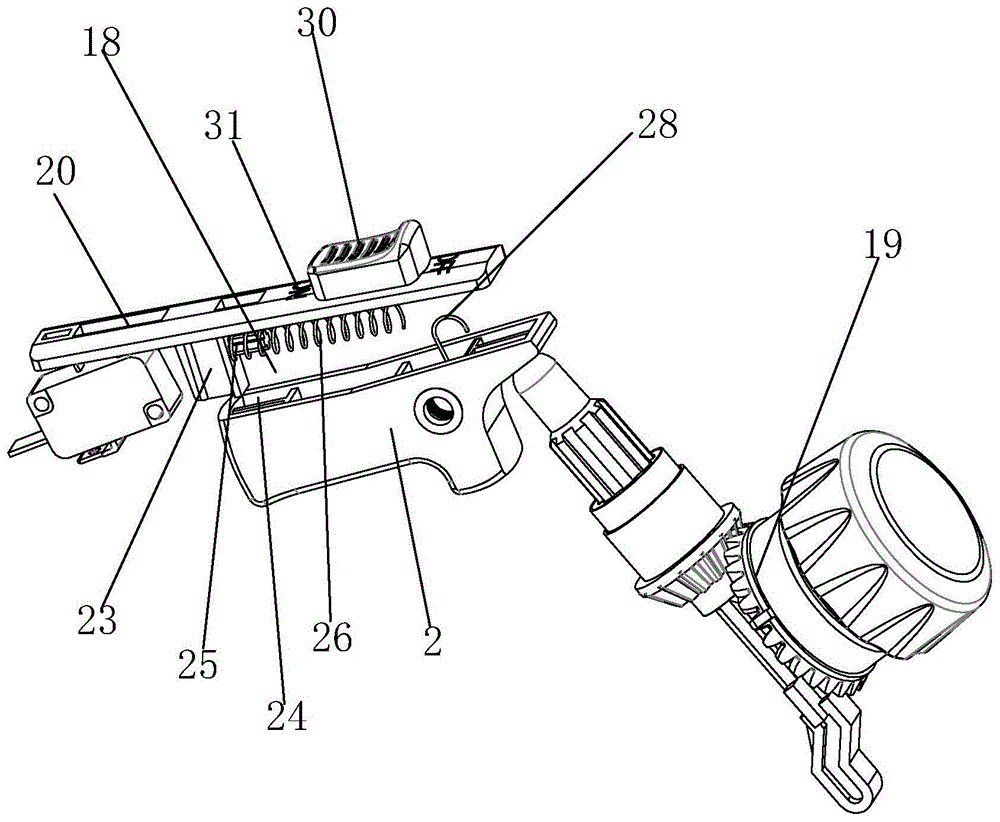
The invention provides a control switch and an adjustment mechanism of an atomizer. It solves the problem that it is easy to accidentally touch the button located under the handle when taking the atomizer, which leads to the opening of the machine. When the present invention is in use, push the push button to move in the direction of the button to start the fan through the fan controller, and the push button drives the fixed rod on the push button to be positioned above the groove on the button, and pinch the button to drive the end of the button away from the adjustment mechanism to rotate around the rod Rotate upward until the slot on the button is snapped into the lower end of the above-mentioned fixed rod. At this time, the atomizer starts to emit water. When the push button or the button is pressed alone, no water is produced. The spring provides a force to the fixed rod away from the button to make the fixed rod The lower end of the fuselage is firmly clamped in the card slot, which is more convenient to use and effectively avoids the situation that the atomizer is started by mistakenly touching the button.
Description
技术领域technical field
本发明设备属于雾化器技术领域,特别涉及一种雾化器的控制开关及调节机构。The device of the invention belongs to the technical field of atomizers, and particularly relates to a control switch and an adjustment mechanism of an atomizer.
背景技术Background technique
雾化器通过内部的风扇转动,使出风口处于水箱内部形成气压差,水箱内部的液体在气压的作用下进入出风口处,在风扇的作用下形成雾状喷射,通过按压按钮启动雾化器内的风扇并驱动连接杆移动来控制出风管内出水口处的开闭,通常来说,连接杆的长度是固定的,通过连接杆使出水口内的堵头移动的距离是一定的,按钮按压后堵头与出水口之间的间隙相同,出水量相同,无法根据实际的使用情况调节出水量的大小,使用时较为不便,且通常通过同一个按钮来同时控制风扇与出水口,在实际使用过程中,拿取雾化器时容易误触位于手柄下方的按钮,导致机器的开启,使用时较为不便,现有技术存在可改进之处。The atomizer is rotated by the internal fan, so that the air outlet is located inside the water tank to form an air pressure difference. The liquid inside the water tank enters the air outlet under the action of air pressure, and forms a mist spray under the action of the fan, and the atomizer is activated by pressing the button. The fan inside and drives the connecting rod to move to control the opening and closing of the water outlet in the air outlet. Generally speaking, the length of the connecting rod is fixed, and the distance of the plug in the water outlet is fixed by the connecting rod. Press the button. The gap between the rear plug and the water outlet is the same, and the water output is the same. The size of the water output cannot be adjusted according to the actual use situation, which is inconvenient to use. Usually, the same button is used to control the fan and the water outlet at the same time. In actual use During the process, when taking the atomizer, it is easy to accidentally touch the button located under the handle, which leads to the opening of the machine, which is inconvenient to use, and there is room for improvement in the existing technology.
发明内容SUMMARY OF THE INVENTION
本发明设备针对拿取雾化器时容易误触位于手柄下方的按钮,导致机器的开启的不足,提供了一种能够避免误触的雾化器的控制开关及调节机构。The device of the invention provides a control switch and an adjustment mechanism of the atomizer which can avoid the accidental touch, aiming at the insufficiency of opening the machine due to easily mistakenly touching the button located under the handle when taking the atomizer.
本发明的发明目的是通过以下技术方案实现的:一种雾化器的控制开关及调节机构,安装在雾化器壳体内,所述控制开关用于控制风扇控制器的开闭,所述调节机构位于上述控制开关及出水管之间,其特征在于,所述控制开关包括用于控制风扇控制器开闭的推钮及用于驱动调节机构移动并转动设置在壳体内的按钮,按钮的一端位于上述推钮的下方,另一端贴靠在上述调节机构上,所述推钮的下端固定设置有一个固定杆,所述按钮远离调节机构一侧的上端面上开设有用于卡接上述固定杆的卡槽,所述固定杆能够随着推钮沿推钮长度方向朝按钮方向移动并通过按压按钮使按钮上的卡槽转动后卡接在上述固定杆上。The purpose of the present invention is achieved through the following technical solutions: a control switch and an adjustment mechanism of an atomizer, which are installed in the atomizer housing, the control switch is used to control the opening and closing of the fan controller, and the adjustment The mechanism is located between the above-mentioned control switch and the water outlet pipe. It is located below the push button, and the other end is abutted on the adjustment mechanism. The fixing rod can move toward the button along the length direction of the push button with the push button, and the clamping groove on the button is rotated by pressing the button and then clamped on the fixing rod.
作为优选,所述壳体上开设有用于卡接杆推钮并使推钮能够沿推钮长度方向往复移动的滑动槽,所述壳体内固定设置有一个转动杆,上述按钮转动设置在该转动杆上。Preferably, the casing is provided with a sliding groove for clamping the rod push button and enabling the push button to reciprocate along the length direction of the push button, a rotating rod is fixedly arranged in the casing, and the button is rotated in the rotating position of the push button. on the rod.
作为优选,所述固定杆朝向按钮的端面上固定设置有一个固定柱,该固定柱外周套设有一个驱动推钮向远离按钮方向移动的弹簧,所述壳体内固定设置有一个用于卡接上述弹簧且开口处朝向固定杆的卡接座,上述弹簧远离固定柱的一端卡接在该卡接座内。Preferably, a fixing column is fixedly arranged on the end face of the fixing rod facing the button, the outer periphery of the fixing column is sleeved with a spring that drives the push button to move away from the button, and a fixing column is fixedly arranged in the casing for clamping The spring has an opening facing the clamping seat of the fixing rod, and one end of the spring away from the fixing column is clamped in the clamping seat.
作为优选,所述转动杆上套设有一个驱动按钮远离调节机构的一端绕转动杆向下转动的扭簧,所述壳体上固定设置有一个卡接柱,该卡接柱位于按钮的上方,所述扭簧的一端卡接在该卡接柱上,按钮的另一端固定设置在按钮上。Preferably, a torsion spring that drives the end of the button away from the adjusting mechanism to rotate downward around the rotating rod is sleeved on the rotating rod, and a clamping post is fixed on the housing, and the clamping post is located above the button. , one end of the torsion spring is clamped on the clamping post, and the other end of the button is fixedly arranged on the button.
作为优选,所述推钮的上端固定设置有一个推块,该推块的上端位于壳体的外侧,所述壳体上开设有用于卡接该推块的活动槽,该活动槽的长度大于推块的长度。Preferably, a push block is fixed on the upper end of the push button, the upper end of the push block is located on the outer side of the casing, and the casing is provided with a movable groove for clamping the push block, and the length of the movable groove is greater than The length of the push block.
作为优选,所述推钮上设置有开启与关闭的标识,两个标识分别位于推钮上推块的两侧,两个标识与推块位于同一直线上且与推钮的长度方向平行。Preferably, the push button is provided with opening and closing signs, the two signs are respectively located on both sides of the push block on the push button, and the two signs and the push block are on the same line and parallel to the length direction of the push button.
作为优选,所述调节机构包括转动设置在壳体内的花键轴及套设在花键轴外周并能够沿花键轴长度方向移动的转动套环,该转动套环内壁上开设有与上述花键轴相配合的导向槽,所述壳体上固定设置有用于限制转动套环沿上述花键轴长度方向移动的限位板,所述花键轴的下端面上开设有延伸至花键轴内部的转动槽,所述转动槽内活动设置有一个顶杆,该顶杆通过螺纹连接活动设置在转动槽内,所述顶杆的两侧分别固定设置有一个导向板,上述壳体内固定设置有用于上述卡接杆的卡接槽并使导向板能够随着顶杆的移动沿着顶杆的长度方向在卡接槽内移动,所述壳体上设置有用于控制转动套环转动的调节旋钮。Preferably, the adjustment mechanism comprises a spline shaft rotatably arranged in the housing and a rotating collar sleeved on the outer circumference of the spline shaft and capable of moving along the length direction of the spline shaft, and the inner wall of the rotating collar is provided with the above-mentioned flower A guide groove matched with the spline shaft, the casing is fixedly provided with a limit plate for restricting the movement of the rotating collar along the length direction of the spline shaft, and the lower end surface of the spline shaft is provided with extending to the spline shaft The internal rotation groove, a mandrel is movably arranged in the rotation groove, the mandrel is movably arranged in the rotation groove through a threaded connection, a guide plate is fixedly arranged on both sides of the ejector rod, and the above-mentioned housing is fixedly arranged There is a clamping groove for the above-mentioned clamping rod, and the guide plate can move in the clamping groove along the length direction of the top rod with the movement of the top rod, and the housing is provided with an adjustment for controlling the rotation of the rotating collar knob.
作为优选,所述调节旋钮转动设置在上述壳体上,所述转动套环朝向上述顶杆的一端固定设置有第一齿轮,所述调节旋钮朝向该转动套环的一端固定设置有始终与上述第一齿轮相啮合的第二齿轮,所述调节旋钮能够通过相互配合的第一齿轮与第二齿轮驱动转动套环绕转动套环中心轴转动。Preferably, the adjusting knob is rotatably arranged on the casing, the first gear is fixedly arranged at one end of the rotating collar facing the top rod, and the end of the adjusting knob facing the rotating collar is fixed with a first gear that is always connected to the above-mentioned The first gear is meshed with the second gear, and the adjusting knob can drive the rotating sleeve to rotate around the central axis of the rotating sleeve through the mutually matched first gear and the second gear.
作为优选,所述第一齿轮为斜齿轮,所述第二齿轮自调节旋钮向转动套环方向逐渐向调节旋钮外周倾斜,所述第二齿轮上齿的长度方向与第一齿轮上齿的长度方向垂直。Preferably, the first gear is a helical gear, the second gear is gradually inclined toward the outer circumference of the adjustment knob from the adjusting knob to the direction of the rotating collar, and the length direction of the teeth on the second gear is the same as the length of the teeth on the first gear. Orientation is vertical.
作为优选,所述转动套环朝向顶杆的一端固定设置有一个限位环,该限位环位于上述第一齿轮内并套设在上述顶杆外周,所述限位环的内径小于上述花键轴的外径,所述顶杆上固定设置有一圈定位环,该定位环的直径大于顶杆的直径且小于限位环的内径。Preferably, one end of the rotating collar facing the ejector rod is fixedly provided with a limit ring, the limit ring is located in the first gear and sleeved on the outer circumference of the ejector rod, and the inner diameter of the limit ring is smaller than the flower The outer diameter of the key shaft, a ring of positioning ring is fixed on the top rod, and the diameter of the positioning ring is larger than the diameter of the top rod and smaller than the inner diameter of the limit ring.
作为优选,所述花键轴远离上述顶杆的一端固定设置有一个压块。Preferably, a pressing block is fixedly arranged at one end of the spline shaft away from the above-mentioned ejector rod.
与现有技术相比,本发明使用时推动推钮向按钮方向移动通过风扇控制器启动风扇,并通过推钮带动推钮上的固定杆位于按钮上卡槽的上方,捏动按钮驱动按钮远离调节机构的一端绕转动杆向上转动,直到按钮上的卡槽卡接在上述固定杆的下端此时雾化器开始出水,单独按压推钮或者按钮时均不出水,弹簧对固定杆提供一个远离按钮方向的力使固定杆的下端稳固的卡接在卡槽内,通过扭簧对按钮远离调节机构的一端提供移动绕转动杆向下转动的力,在使用者松开按钮后再扭簧的作用下带动按钮远离调节机构的一端绕转动杆向下转动时卡槽与固定杆脱离,固定杆在弹簧的作用下沿滑动槽向远离按钮的方向移动并控制风扇控制器关闭,使用时较为方便有效避免误触按钮导致雾化器启动的情况出现。Compared with the prior art, the present invention pushes the push button to move in the direction of the button to start the fan through the fan controller, and drives the fixed rod on the push button to be positioned above the slot on the button through the push button, and pushes the button to drive the button away from the button. One end of the adjustment mechanism rotates up around the rotating rod until the slot on the button is engaged with the lower end of the above-mentioned fixed rod. At this time, the atomizer starts to emit water. When the push button or the button is pressed alone, no water is produced. The spring provides a distance from the fixed rod. The force in the direction of the button makes the lower end of the fixed rod firmly clamped in the slot, and the end of the button away from the adjustment mechanism is provided with a force to move and rotate downward around the rotating rod through the torsion spring. Under the action, the end of the button is driven away from the adjusting mechanism to rotate downward around the rotating rod. When the card slot is separated from the fixed rod, the fixed rod moves along the sliding groove away from the button under the action of the spring and controls the fan controller to close, which is more convenient to use. Effectively avoid the situation where the atomizer is started by accidentally touching the button.
附图说明Description of drawings
图1为本发明安装后的整体结构视图;Fig. 1 is the overall structure view after installation of the present invention;
图2为图1中C处的放大图;Fig. 2 is the enlarged view of C place in Fig. 1;
图3本发明的整体结构视图;Figure 3 is an overall structural view of the present invention;
图4为控制开关的剖切视图;4 is a cutaway view of a control switch;
图5为控制开关闭合后的整体结构视图;Fig. 5 is the overall structure view after the control switch is closed;
图6为图1中A处的放大图;Fig. 6 is the enlarged view of A place in Fig. 1;
图7为调节机构的整体结构视图;Fig. 7 is the overall structure view of the adjustment mechanism;
图8为调节机构的结构爆炸图;Figure 8 is an exploded view of the structure of the adjustment mechanism;
图9为调节机构的剖切视图;Figure 9 is a cutaway view of the adjustment mechanism;
图10为图9中B处的放大图。FIG. 10 is an enlarged view of B in FIG. 9 .
图中标记:1、壳体;2、按钮;3、出水管;4、花键轴;5、转动套环;6、导向槽;7、限位板;8、转动槽;9、顶杆;10、导向板;11、卡接槽;12、调节旋钮;13、第一齿轮;14、第二齿轮;15、限位环;16、定位环;17、压块;18、控制开关;19、调节机构;20、推钮; 21、滑动槽;22、转动杆;23、固定杆;24、卡槽;25、固定柱;26、弹簧;27、卡接座;28、扭簧;29、卡接柱;30、推块;31、活动槽;32、标识。Markings in the figure: 1. Shell; 2. Button; 3. Outlet pipe; 4. Spline shaft; 5. Rotating collar; 6. Guide groove; 7. Limit plate; 8. Rotating groove; 9. Ejector ; 10, guide plate; 11, snap groove; 12, adjustment knob; 13, first gear; 14, second gear; 15, limit ring; 16, positioning ring; 17, pressure block; 18, control switch; 19. Adjustment mechanism; 20. Push button; 21. Sliding slot; 22. Rotating rod; 23. Fixed rod; 24. Slot; 25. Fixed post; 26. Spring; 29. Clamping post; 30. Push block; 31. Active slot; 32. Logo.
具体实施方式Detailed ways
下面结合附图所表示的实施例对本发明作进一步描述:如图1-5所示,一种雾化器的控制开关18及调节机构19,安装在雾化器壳体1内,所述控制开关18用于控制风扇控制器的开闭,所述调节机构19位于上述控制开关18及出水管之间,所述控制开关18包括用于控制风扇控制器开闭的推钮20及用于驱动调节机构19移动的按钮2,所述壳体1上开设有用于卡接杆推钮20并使推钮20能够沿推钮20长度方向往复移动的滑动槽21,所述壳体1内固定设置有一个转动杆22,该按钮2转动设置在该转动杆22上,按钮2的一端位于上述推钮20的下方,另一端贴靠在上述调节机构19上,所述推钮20的下端固定设置有一个固定杆23,所述按钮2远离调节机构19一侧的上端面上开设有用于卡接上述固定杆23的卡槽24,所述固定杆23能够沿滑动槽21长度方向朝按钮2方向移动并通过按压按钮2使按钮2绕转动杆22转动使按钮2上的卡槽24绕转动杆22向上转动并卡接在上述固定杆23上。The present invention will be further described below in conjunction with the embodiments shown in the accompanying drawings: As shown in Figures 1-5, a
所述固定杆23朝向按钮2的端面上固定设置有一个固定柱25,该固定柱25外周套设有一个驱动推钮20向远离按钮2方向移动的弹簧26,所述壳体1内固定设置有一个用于卡接上述弹簧26且开口处朝向固定杆23的卡接座27,上述弹簧26远离固定柱25的一端卡接在该卡接座27内。所述转动杆22上套设有一个驱动按钮2远离调节机构19的一端绕转动杆22向下转动的扭簧28,所述壳体1上固定设置有一个卡接柱29,该卡接柱29位于按钮2的上方,所述扭簧28的一端卡接在该卡接柱29上,按钮2的另一端固定设置在按钮2上。A fixing
所述推钮20的上端固定设置有一个推块30,该推块30的上端位于壳体1的外侧,所述壳体1上开设有用于卡接该推块30的活动槽31,该活动槽31的长度大于推块30的长度。所述推钮20上设置有开启与关闭的标识32,两个标识32分别位于推钮20上推块30的两侧,两个标识32与推块30位于同一直线上且与推钮20的长度方向平行。能够较为直观的显示雾化器的工作状态。A
使用时推动推钮20向按钮2方向移动通过风扇控制器启动风扇,并通过推钮20带动推钮20上的固定杆23位于按钮2上卡槽24的上方,捏动按钮2驱动按钮2远离调节机构19的一端绕转动杆22向上转动,直到按钮2上的卡槽24卡接在上述固定杆23的下端此时雾化器开始出水,单独按压推钮20或者按钮2时均不出水,弹簧26对固定杆23提供一个远离按钮2方向的力使固定杆23的下端稳固的卡接在卡槽24内,通过扭簧28对按钮2远离调节机构19的一端提供移动绕转动杆22向下转动的力,在使用者松开按钮2后再扭簧28的作用下带动按钮2远离调节机构19的一端绕转动杆22向下转动时卡槽24与固定杆23脱离,固定杆23在弹簧26的作用下沿滑动槽21向远离按钮2的方向移动并控制风扇控制器关闭,使用时较为方便有效避免误触按钮2导致雾化器启动的情况出现When in use, push the
如图6-10所示,所述调节机构19包括转动设置在壳体1内的花键轴4及套设在花键轴4外周并能够沿花键轴4长度方向移动的转动套环5,该转动套环5内壁上开设有与上述花键轴4相配合的导向槽6,所述壳体1上固定设置有用于限制转动套环5沿上述花键轴4长度方向移动的限位板7,所述花键轴4的下端面上开设有延伸至花键轴4内部的转动槽8,所述转动槽8内活动设置有一个顶杆9,该顶杆9通过螺纹连接活动设置在转动槽8内,所述顶杆9的两侧分别固定设置有一个导向板10,上述壳体1内固定设置有用于上述卡接杆的卡接槽11并使导向板10能够随着顶杆9的移动沿着顶杆9的长度方向在卡接槽11内移动,所述壳体1上设置有用于控制转动套环5转动的调节旋钮12。As shown in FIGS. 6-10 , the
所述调节旋钮12转动设置在上述壳体1上,所述转动套环5朝向上述顶杆9的一端固定设置有第一齿轮13,所述调节旋钮12朝向该转动套环5的一端固定设置有始终与上述第一齿轮13相啮合的第二齿轮14,所述调节旋钮12能够通过相互配合的第一齿轮13与第二齿轮14驱动转动套环5绕转动套环5中心轴转动。通过旋转旋钮,旋钮通过始终相互啮合第一齿轮13与第二齿轮14带动带动套设在花键轴4上的转动套环5绕花键轴4的转动中心转动,顶杆9通过固定设置在顶杆9两侧的导向板10卡接在卡接槽11内限制顶杆9的转动,通过螺纹连接的花键轴4与顶杆9在转动的花键轴4的驱动下带动顶杆9沿卡接槽11的长度方向移动,达到调节花键轴4与顶杆9整体长度的目的,通过按钮2按压长度不同的调节机构来调节出水管3内堵头与出水口之间的间隙大小,实现调节出水量大小的目的,结构简单调节较为方便。The adjusting
所述第一齿轮13为斜齿轮,所述第二齿轮14自调节旋钮12向转动套环5方向逐渐向调节旋钮12外周倾斜,所述第二齿轮14上齿的长度方向与第一齿轮13上齿的长度方向垂直。通过第二齿轮14上齿的长度方向与第一齿轮13上齿的长度方向垂直,旋转调节旋钮12的力能够较为完整的传递至第一齿轮13上,转动时较为省力。The
所述转动套环5朝向顶杆9的一端固定设置有一个限位环15,该限位环15位于上述第一齿轮13内并套设在上述顶杆9外周,所述限位环15的内径小于上述花键轴4的外径,所述顶杆9上固定设置有一圈定位环16,该定位环16的直径大于顶杆9的直径且小于限位环15的内径。装配时通过将花键轴4的下端贴靠在限位环15朝向花键轴4的端面上,顶杆9通过螺纹连接转配进花键轴4内,直到定位环16贴靠在上述花键轴4朝向顶杆9的端面上完成装配,通过定位环16对顶杆9的装配位置进行限定,安装时定位较为精确。One end of the
所述花键轴4远离上述顶杆9的一端固定设置有一个压块17。该压块17为球型压块17,雾化器上的按钮2按压驱动花键轴4移动,按钮2始终贴靠在压块17上,且按钮2在按压的过程中始终处于旋转的状态,按钮2的端面始终贴靠在压块17上,避免在按压过程中出现顿挫感,按压过程更加顺畅。One end of the
文中所描述的具体实施例仅仅是对本发明精神作举例说明。本发明所属技术领域的技术人员可以对所描述的具体实施例做各种各样的修改或补充或采用类似的方式替代,但并不会偏离本发明的精神或者超越所附权利要求书所定义的范围。The specific embodiments described herein are merely illustrative of the spirit of the invention. Those skilled in the art to which the present invention pertains can make various modifications or additions to the described specific embodiments or substitute in similar manners, but will not deviate from the spirit of the present invention or go beyond the definitions of the appended claims range.
Claims (10)
Priority Applications (3)
| Application Number | Priority Date | Filing Date | Title |
|---|---|---|---|
| CN202010878520.8A CN112007779B (en) | 2020-08-27 | 2020-08-27 | A control switch and regulating mechanism of an atomizer |
| PCT/CN2020/129315 WO2022041504A1 (en) | 2020-08-27 | 2020-11-17 | Atomizer control switch and adjustment mechanism |
| US18/682,447 US12521746B2 (en) | 2020-08-27 | 2020-11-17 | Control switch and regulating mechanism for atomizer |
Applications Claiming Priority (1)
| Application Number | Priority Date | Filing Date | Title |
|---|---|---|---|
| CN202010878520.8A CN112007779B (en) | 2020-08-27 | 2020-08-27 | A control switch and regulating mechanism of an atomizer |
Publications (2)
| Publication Number | Publication Date |
|---|---|
| CN112007779A true CN112007779A (en) | 2020-12-01 |
| CN112007779B CN112007779B (en) | 2024-12-03 |
Family
ID=73503548
Family Applications (1)
| Application Number | Title | Priority Date | Filing Date |
|---|---|---|---|
| CN202010878520.8A Active CN112007779B (en) | 2020-08-27 | 2020-08-27 | A control switch and regulating mechanism of an atomizer |
Country Status (1)
| Country | Link |
|---|---|
| CN (1) | CN112007779B (en) |
Cited By (1)
| Publication number | Priority date | Publication date | Assignee | Title |
|---|---|---|---|---|
| WO2022198799A1 (en) * | 2020-12-04 | 2022-09-29 | 浙江普莱得电器股份有限公司 | Static electricity generating apparatus of atomizer |
Citations (6)
| Publication number | Priority date | Publication date | Assignee | Title |
|---|---|---|---|---|
| US20130256426A1 (en) * | 2011-01-14 | 2013-10-03 | Steve D. Becker | Control valve for airless sprayer pressure adjustment |
| CN207025646U (en) * | 2017-05-03 | 2018-02-23 | 重庆铂汉塑胶有限公司 | One kind rotation adjusting knob |
| CN207446556U (en) * | 2017-11-02 | 2018-06-05 | 广州市范乐医药科技有限公司 | A kind of household atomizer easy to clean |
| CN108480085A (en) * | 2018-04-23 | 2018-09-04 | 江苏蔚金模塑股份有限公司 | A kind of auto parts and components spray head being conveniently replaceable |
| CN109833993A (en) * | 2017-11-27 | 2019-06-04 | 广西明福科技有限公司 | A kind of automation controller |
| CN212524637U (en) * | 2020-08-27 | 2021-02-12 | 浙江普莱得电器股份有限公司 | Control switch and adjustment mechanism of atomizer |
-
2020
- 2020-08-27 CN CN202010878520.8A patent/CN112007779B/en active Active
Patent Citations (6)
| Publication number | Priority date | Publication date | Assignee | Title |
|---|---|---|---|---|
| US20130256426A1 (en) * | 2011-01-14 | 2013-10-03 | Steve D. Becker | Control valve for airless sprayer pressure adjustment |
| CN207025646U (en) * | 2017-05-03 | 2018-02-23 | 重庆铂汉塑胶有限公司 | One kind rotation adjusting knob |
| CN207446556U (en) * | 2017-11-02 | 2018-06-05 | 广州市范乐医药科技有限公司 | A kind of household atomizer easy to clean |
| CN109833993A (en) * | 2017-11-27 | 2019-06-04 | 广西明福科技有限公司 | A kind of automation controller |
| CN108480085A (en) * | 2018-04-23 | 2018-09-04 | 江苏蔚金模塑股份有限公司 | A kind of auto parts and components spray head being conveniently replaceable |
| CN212524637U (en) * | 2020-08-27 | 2021-02-12 | 浙江普莱得电器股份有限公司 | Control switch and adjustment mechanism of atomizer |
Cited By (1)
| Publication number | Priority date | Publication date | Assignee | Title |
|---|---|---|---|---|
| WO2022198799A1 (en) * | 2020-12-04 | 2022-09-29 | 浙江普莱得电器股份有限公司 | Static electricity generating apparatus of atomizer |
Also Published As
| Publication number | Publication date |
|---|---|
| CN112007779B (en) | 2024-12-03 |
Similar Documents
| Publication | Publication Date | Title |
|---|---|---|
| CN112090618A (en) | Atomizer | |
| WO2022041504A1 (en) | Atomizer control switch and adjustment mechanism | |
| CN205047960U (en) | Button is shaft type flow regulator even | |
| US11472017B2 (en) | Power tool | |
| CN112007779A (en) | Control switch and adjustment mechanism of atomizer | |
| CN110206915A (en) | Gas valve capable of linearly adjusting firepower and gas stove | |
| CN212524637U (en) | Control switch and adjustment mechanism of atomizer | |
| US20240367295A1 (en) | Power Tool for Reversing and Holding with Single Hand | |
| CN201832741U (en) | Spray gun | |
| CN111023382B (en) | Telescopic automatic induction humidifier | |
| CN105743278A (en) | Treadmill lifting drive device | |
| CN201760361U (en) | Shower head capable of adjusting flux | |
| CN103191847B (en) | Spray gun provided with extension rod and rotating mechanism | |
| CN212407747U (en) | Shower bath | |
| CN221847518U (en) | Shower head with integrated control knob | |
| CN209229048U (en) | Valve stem equipment | |
| CN215429888U (en) | Atomizer adjustment mechanism | |
| CN216150089U (en) | Electrostatic generating device of atomizer | |
| CN107626462B (en) | Universal touch type waterway switching shower head | |
| CN117960419A (en) | Shower head with integrated control knob | |
| CN205725316U (en) | A treadmill lifting drive device | |
| CN216025671U (en) | Atomizer and generating device thereof | |
| CN206509137U (en) | A kind of electric spray gun of adjustable spraying flow | |
| CN222657744U (en) | Game handle capable of switching trigger key travel | |
| CN222277619U (en) | Novel air valve controller |
Legal Events
| Date | Code | Title | Description |
|---|---|---|---|
| PB01 | Publication | ||
| PB01 | Publication | ||
| SE01 | Entry into force of request for substantive examination | ||
| SE01 | Entry into force of request for substantive examination | ||
| GR01 | Patent grant | ||
| GR01 | Patent grant |