CN112041237A - Liquid dispenser with squeezable liquid reservoir - Google Patents
Liquid dispenser with squeezable liquid reservoir Download PDFInfo
- Publication number
- CN112041237A CN112041237A CN201980030094.8A CN201980030094A CN112041237A CN 112041237 A CN112041237 A CN 112041237A CN 201980030094 A CN201980030094 A CN 201980030094A CN 112041237 A CN112041237 A CN 112041237A
- Authority
- CN
- China
- Prior art keywords
- discharge
- dispenser
- additional features
- cover
- following additional
- Prior art date
- Legal status (The legal status is an assumption and is not a legal conclusion. Google has not performed a legal analysis and makes no representation as to the accuracy of the status listed.)
- Pending
Links
Images


Classifications
-
- B—PERFORMING OPERATIONS; TRANSPORTING
- B65—CONVEYING; PACKING; STORING; HANDLING THIN OR FILAMENTARY MATERIAL
- B65D—CONTAINERS FOR STORAGE OR TRANSPORT OF ARTICLES OR MATERIALS, e.g. BAGS, BARRELS, BOTTLES, BOXES, CANS, CARTONS, CRATES, DRUMS, JARS, TANKS, HOPPERS, FORWARDING CONTAINERS; ACCESSORIES, CLOSURES, OR FITTINGS THEREFOR; PACKAGING ELEMENTS; PACKAGES
- B65D35/00—Pliable tubular containers adapted to be permanently or temporarily deformed to expel contents, e.g. collapsible tubes for toothpaste or other plastic or semi-liquid material; Holders therefor
- B65D35/44—Closures
- B65D35/46—Closures with valves
-
- B—PERFORMING OPERATIONS; TRANSPORTING
- B65—CONVEYING; PACKING; STORING; HANDLING THIN OR FILAMENTARY MATERIAL
- B65D—CONTAINERS FOR STORAGE OR TRANSPORT OF ARTICLES OR MATERIALS, e.g. BAGS, BARRELS, BOTTLES, BOXES, CANS, CARTONS, CRATES, DRUMS, JARS, TANKS, HOPPERS, FORWARDING CONTAINERS; ACCESSORIES, CLOSURES, OR FITTINGS THEREFOR; PACKAGING ELEMENTS; PACKAGES
- B65D47/00—Closures with filling and discharging, or with discharging, devices
- B65D47/04—Closures with discharging devices other than pumps
- B65D47/06—Closures with discharging devices other than pumps with pouring spouts or tubes; with discharge nozzles or passages
- B65D47/08—Closures with discharging devices other than pumps with pouring spouts or tubes; with discharge nozzles or passages having articulated or hinged closures
- B65D47/0804—Closures with discharging devices other than pumps with pouring spouts or tubes; with discharge nozzles or passages having articulated or hinged closures integrally formed with the base element provided with the spout or discharge passage
- B65D47/0828—Closures with discharging devices other than pumps with pouring spouts or tubes; with discharge nozzles or passages having articulated or hinged closures integrally formed with the base element provided with the spout or discharge passage and elastically biased towards the open position only
-
- B—PERFORMING OPERATIONS; TRANSPORTING
- B65—CONVEYING; PACKING; STORING; HANDLING THIN OR FILAMENTARY MATERIAL
- B65D—CONTAINERS FOR STORAGE OR TRANSPORT OF ARTICLES OR MATERIALS, e.g. BAGS, BARRELS, BOTTLES, BOXES, CANS, CARTONS, CRATES, DRUMS, JARS, TANKS, HOPPERS, FORWARDING CONTAINERS; ACCESSORIES, CLOSURES, OR FITTINGS THEREFOR; PACKAGING ELEMENTS; PACKAGES
- B65D47/00—Closures with filling and discharging, or with discharging, devices
- B65D47/04—Closures with discharging devices other than pumps
- B65D47/20—Closures with discharging devices other than pumps comprising hand-operated members for controlling discharge
- B65D47/2018—Closures with discharging devices other than pumps comprising hand-operated members for controlling discharge comprising a valve or like element which is opened or closed by deformation of the container or closure
- B65D47/2056—Closures with discharging devices other than pumps comprising hand-operated members for controlling discharge comprising a valve or like element which is opened or closed by deformation of the container or closure lift valve type
- B65D47/2081—Closures with discharging devices other than pumps comprising hand-operated members for controlling discharge comprising a valve or like element which is opened or closed by deformation of the container or closure lift valve type in which the deformation raises or lowers the valve port
Landscapes
- Engineering & Computer Science (AREA)
- Mechanical Engineering (AREA)
- Closures For Containers (AREA)
- Containers And Packaging Bodies Having A Special Means To Remove Contents (AREA)
Abstract
Description
技术领域technical field
本发明涉及一种用于将液体输出在使用者的皮肤上、也就是用于进行局部的使用的乳液分配器。这样的分配器用在美容及制药领域内。The present invention relates to a lotion dispenser for delivering liquid on the skin of a user, ie for topical use. Such dispensers are used in the cosmetic and pharmaceutical fields.
背景技术Background technique
所述类型的以及按本发明的乳液分配器通常被构造为管式分配器并且除了通常一件式的管子本体之外也包括被安置在管子本体上的、带有出料口的塑料出料头。所述出料头为了避免干燥并且/或者为了改进可竖立性而具有铰链盖,所述铰链盖在关闭的状态中覆盖出料口。Emulsion dispensers of the type described and according to the invention are generally designed as tube dispensers and, in addition to the generally one-piece tube body, also comprise a plastic discharge material with a discharge opening which is attached to the tube body head. In order to avoid drying out and/or to improve the erectability, the spout has a hinged cover, which covers the spout in the closed state.
由现有技术已知大量这样的所述类型的乳液分配器。然而,此外存在着以便宜的制造成本保证操纵时的高度的舒适性并且保证适意的使用的需求。A large number of emulsion dispensers of this type are known from the prior art. In addition, however, there is a need to ensure a high degree of comfort during handling and to ensure pleasant use at low manufacturing costs.
发明内容SUMMARY OF THE INVENTION
本发明的任务是,提供一种能够成本低廉地制造的乳液分配器,该乳液分配器的突出之处在于在触觉上适意的操作和使用。The object of the present invention is to provide a cost-effectively producible lotion dispenser which is distinguished by a tactilely pleasant handling and use.
按照本发明,按照本发明的第一方面,为此提出一种用于将液体输出在使用者的皮肤上的乳液分配器,所述乳液分配器拥有带有排出管接头的液体储存器以及带有排出通道和处于排出通道的端部上的出料口的出料头。所述出料头包括带有阀压力室的排出阀,所述排出阀能够通过所述阀压力室的内压来打开。According to the invention, according to a first aspect of the invention, a lotion dispenser is proposed for this purpose for delivering a liquid to the skin of a user, the lotion dispenser having a liquid reservoir with a drain connection and a belt A discharge head with a discharge channel and a discharge opening on the end of the discharge channel. The discharge head includes a discharge valve with a valve pressure chamber which can be opened by the internal pressure of the valve pressure chamber.
按本发明的乳液分配器被构造用于输出较高粘度的液体、也就是乳状或者胶状的物质。按本发明的分配器的液体储存器因此装有这样的液体,其中能够涉及纯美容的或者纯制药方面起作用的液体或者具有美容的和制药的使用用途的混合形式。The emulsion dispenser according to the invention is designed to dispense relatively viscous liquids, ie, milky or gel-like substances. The liquid reservoir of the dispenser according to the invention is thus filled with liquids which can be purely cosmetic or purely pharmaceutical liquids or mixed forms with cosmetic and pharmaceutical uses.
在此提出,所述出料头尤其包括两个构件、也就是内部构件和外部构件。所述外部构件具有端壁,该端壁被排出通道所贯穿并且在所述端壁中设置了所述出料口。所述内部构件包括沿着主延伸方向延伸的连接管接头,该连接管接头用于连接在液体储存器的外部管接头上。此外,所述内部构件具有阀表面,该阀表面与排出通道的入口对置地布置,其中所述阀表面和所述排出通道的入口一起形成所提到的排出阀并且如此彼此相协调,从而通过阀表面和排出通道的相对于彼此的相对移动能够打开并且关闭所述排出阀。所述内部构件和外部构件为了形成阀压力室而沿着所述外部构件的侧面的内侧面上的环绕的固定区域固定地并且密封地彼此连接。It is proposed here that the tap head comprises in particular two components, namely an inner component and an outer component. The outer member has an end wall which is penetrated by a discharge channel and in which the spout is provided. The inner member comprises a connecting pipe fitting extending along the main extension direction for connecting to an external pipe fitting of the liquid reservoir. In addition, the inner component has a valve surface which is arranged opposite the inlet of the outlet channel, wherein the valve surface and the inlet of the outlet channel together form the outlet valve mentioned and are coordinated with each other in such a way that through Relative movement of the valve surface and the discharge channel with respect to each other can open and close the discharge valve. In order to form the valve pressure chamber, the inner part and the outer part are fixedly and sealingly connected to one another along a circumferential fastening region on the lateral inner side of the outer part.
所述内部构件和外部构件由此一起限定了阀压力室,液体被从液体储存器、尤其是管子压入到所述阀压力室中。升高的压力引起所述内部构件及外部构件方面的彼此对置的壁体的隔开并且由此相起阀的打开。所述乳液现在能够通过所述端壁中的出料口以给送的方式来逸出。所述乳液由此尤其优选到达端壁的面状的外侧面上,它从那里被施加在使用者的皮肤上。所提到的外侧面因此优选无尖锐的棱边,因为这会在皮肤接触中被感觉到令人不快。The inner and outer components thus together define a valve pressure chamber into which the liquid is pressed from a liquid reservoir, in particular a tube. The increased pressure causes the walls of the inner and outer components facing each other to separate from each other and thus to open the valve. The emulsion can now escape in a fed manner through the outlet opening in the end wall. The emulsion thus particularly preferably reaches the planar outer side of the end wall, from where it is applied to the skin of the user. The mentioned outer side is therefore preferably free of sharp edges, since this would be perceived as unpleasant in skin contact.
所述出料头拥有铰链盖,该铰链盖在关闭的状态中覆盖出料口并且该铰链盖在一侧设有铰链并且在与这一侧对置的情况下设有用于闭合地固定在外部构件上的第一卡锁棱边。在此,所述铰链盖优选是外部构件的一件式的部件,所述外部构件的基本上不能活动的部件与所述内部构件一起形成出料头的基座并且所述铰链盖作为能活动的部件能够被一件式地喷铸在所述外部构件上。The outlet head has a hinged cover which, in the closed state, covers the outlet opening and is provided with a hinge on one side and, opposite this side, for a closed attachment to the outside. The first locking edge on the component. In this case, the hinged cover is preferably a one-piece part of the outer component, the substantially immovable part of the outer component together with the inner component forms the base of the tap head and the hinged cover as a movable The components can be cast in one piece on the outer member.
在所述外部构件的不能活动的部件上设置了释放键,该释放键设有第二卡锁棱边,所述第二卡锁棱边在铰链盖关闭时与所述铰链盖上的第一卡锁棱边卡锁在一起并且通过所述释放键的压入能够从这种卡锁状态中释放出来,从而能够打开所述铰链盖。A release key is provided on the immovable part of the outer component, which release key is provided with a second latching edge which, when the hinge lid is closed, is in contact with the first latching edge on the hinge lid. The latching edges are latched together and can be released from this latched state by pressing the release key, so that the hinge lid can be opened.
所述内部构件在固定区域中被固定在外部构件上,所述固定区域关于主延伸方向布置在释放键的高度上,从而在操纵时朝所述固定区域的方向移动所述释放键。The inner member is fastened to the outer member in a fixing area, which is arranged at the height of the release key with respect to the main extension direction, so as to move the release key in the direction of the fixing area when actuated.
为了打开所述铰链盖,使用者压入所提到的释放键。在此,所期望的是,这样的操纵适意轻便,而不存在无意地进行释放的危险。To open the hinged cover, the user presses in the mentioned release key. Here, it is desirable that such manipulations be comfortable and easy without the risk of unintentional release.
此外,所期望的是,所述释放键的可压入性以所定义的方式来限定。这一点按照本发明通过以下方式来实现,即:朝所述固定区域的方式来移动所述释放键。所述出料头的这个区域具有高的稳定性,因为在其当中所述内部构件与所述外部构件彼此连接。机械的耦合器件本身加固了这个区域。另外,所述内部构件的结构及其材料选择能够在这里保证了特别稳定的构造。Furthermore, it is desirable that the depressability of the release key be defined in a defined manner. This is achieved according to the invention by moving the release key in a manner towards the fixing area. This region of the tap head has a high stability, since the inner and outer members are connected to each other in it. The mechanical coupling device itself reinforces this area. In addition, the structure of the internal components and the choice of their materials can ensure a particularly stable construction here.
所述释放键由此只能以限定的方式来压入,直至其被挤压到稳定的固定区域上并且不再能移动。所述可活动性的这种清楚的限定被感觉到在触觉上是适意的并且降低了所述释放键无意地被折断的危险。The release key can thus only be pressed in in a defined manner until it is pressed against the stable fastening area and can no longer be moved. This clear definition of mobility is felt tactilely pleasing and reduces the risk of the release key being unintentionally broken.
在所述固定区域中,所述外部构件和所述内部构件优选通过咬合连接来密封地连接。所述构件之一、尤其是外部构件为此具有环绕的槽,另一个构件的环绕的边条、尤其是内部构件的外部边缘密封地并且固定地咬合到所述环绕的槽中。In the fixing region, the outer component and the inner component are preferably hermetically connected by a snap-fit connection. For this purpose, one of the components, in particular the outer component, has a circumferential groove into which the circumferential edge of the other component, in particular the outer edge of the inner component, engages in a sealing and fixed manner.
所述内部构件优选拥有横向于主延伸方向延伸的环形区段,所述环形区段的外圆周在固定区域中与所述外部构件固定地并且密封地连接。这个环形区段具有径向的延伸方向,所述径向的延伸方向反向于作用到释放键上的压入力并且由此拥有特别好的加固作用。The inner component preferably has an annular section extending transversely to the main direction of extension, the outer circumference of which is connected fixedly and sealingly to the outer component in the fastening region. This annular section has a radial extension which opposes the pressing-in force acting on the release key and thus has a particularly good reinforcing effect.
所述外部构件优选由倒不如说是软塑料制成,因为这对于所述铰链的功能、对于所述释放键的可变形性并且对于所述端壁的被感觉到适意的柔性来说是有利的。相对于此,所述内部构件能够由比所述外部构件硬的并且弹性小的材料制成。这使得装配变得容易并且同时有利于所述固定区域的刚性。The outer member is preferably made of rather soft plastic, as this is advantageous for the function of the hinge, for the deformability of the release key and for the perceived flexibility of the end wall of. In contrast, the inner part can be made of a material that is harder and less elastic than the outer part. This facilitates assembly and at the same time contributes to the rigidity of the fixing region.
作为替代方案或者补充方案,所述内部构件至少在其环形区段的区域中具有比与所述外部构件的、与内部构件一起限定了阀压力室的端壁大的壁厚。这也有利于所述端壁的柔性和所述固定区域的刚性。As an alternative or in addition, the inner component has a greater wall thickness than the end wall of the outer component, which together with the inner component defines the valve pressure chamber, at least in the region of its annular section. This also contributes to the flexibility of the end wall and the rigidity of the securing area.
所述内部构件尤其优选具有基本上平坦的表面区段,所述连接管接头在一侧从所述表面区段上突起并且所述表面区段的外部区域形成所提到的环形区段。所述表面区段在此优选在连接管接头的内侧设有所述阀表面以及至少一个液体穿孔。所述内部构件由此优选具有原则上平坦的形状,仅仅所述连接管接头以及必要时形成内部构件的阀表面的结构从所述平坦的形状上突起。The inner part particularly preferably has a substantially flat surface section, from which the connecting pipe joint protrudes on one side and the outer region of which forms the aforementioned annular section. In this case, the surface section is preferably provided with the valve surface and at least one fluid perforation on the inside of the connecting pipe connection. The inner part thus preferably has a substantially flat shape, from which only the connecting pipe connections and possibly the structures forming the valve surfaces of the inner part protrude.
所述释放键尤其能够被构造为在一侧弹性地被模制在外部构件上的释放舌,在该释放舌的远端上设置了所述卡锁棱边。在此优选规定,所述释放键通过缝隙与所述外部构件的周围的侧面分开。这种分开在仅仅在一侧将释放键连接到至少部分地包围的侧壁上的情况下通过缝隙来实现,这种分开能够实现轻易的压入。尽管如此不用担心由于在所述固定区域中的碰撞而引起的释放键的折断。The release key can in particular be designed as a release tongue which is elastically molded on one side on the outer component, the locking edge being provided on the distal end of the release tongue. In this case, provision is preferably made for the release key to be separated from the surrounding flanks of the outer component by a gap. This separation is effected by means of the slot with only one side connecting the release key to the at least partially enclosed side wall, which allows easy pressing in. However, there is no need to worry about breaking the release key due to a collision in the securing area.
所述铰链盖优选如此成形或者设有这样的铰链,使得其在关闭的状态中处于预应力之下并且在按压释放键时自动地弹开。这样的预应力一方面是有利的,因为由此仅仅所述释放键足以用于将分配器置于准备好出料的状态中,而所述铰链盖则不必手动地尤其优选以偏转180°的方式来一直置于其最终位置中。但是,所述预应力此外是有利的,因为其将铰链盖与释放键之间的卡锁连接保持在应力之下。尽管所述释放键本身的想要的轻便性,由此也禁止无意地压下所述释放健。The hinged cover is preferably shaped or provided with a hinge such that in the closed state it is under prestress and automatically snaps open when the release button is pressed. Such a prestressing is advantageous on the one hand, since only the release key is thus sufficient for placing the dispenser in the ready-to-discharge state, while the hinged lid does not have to be manually, particularly preferably, pivoted by 180°. way to remain in its final position. However, the prestress is also advantageous because it keeps the snap-fit connection between the hinge cover and the release key under stress. Despite the desired portability of the release key itself, unintentional depression of the release key is thereby prohibited.
为了能够实现所述铰链盖的尽可能完全的弹开,所述用于连接铰链盖的铰链优选具有如此特性,使得其在关闭的状态中处于应力之下,所述应力在打开的过程中松驰。In order to be able to open the hinged lid as completely as possible, the hinge for connecting the hinged lid preferably has such properties that in the closed state it is under stress which loosens during opening Chi.
对于所述铰链盖的可靠的独立的弹开来说,也特别有利的是,这个铰链盖在应力之下在接触的区域中抵靠在所述外部构件的端壁上。所述铰链盖的内侧面抵靠在所述外部构件的端壁上,这对于出料口的封闭来说已经是有利的。通过由此在端壁或者铰链盖中存在的应力,也以所描述的方式有利于打开。It is also particularly advantageous for a reliable and independent opening of the hinge cover, which bears against the end wall of the outer component under stress in the area of contact. The inner side of the hinged cover rests on the end wall of the outer member, which is already advantageous for the closure of the spout. Opening is also facilitated in the manner described by the stresses thus present in the end walls or hinged lids.
尤其所述铰链盖能够具有将外部构件的端壁覆盖的遮盖壁。指向里面的一侧形成封闭面,该封闭面朝出料口的方向拱起并且由此在关闭的状态中在所述遮盖壁的预应力下在包围出料口的情况下抵靠在端壁上。In particular, the hinged cover can have a cover wall which covers the end wall of the outer component. The side pointing inwards forms a closing surface which is arched in the direction of the outlet opening and thus rests against the end wall in the closed state under the prestressing of the cover wall while surrounding the outlet opening superior.
所提到的遮盖壁为此具有以下尺寸,所述尺寸优选超过端壁的尺寸。至少在内侧面上在封闭面的区域中、但是尤其优选在内侧并且在外侧,所述遮盖壁优选没有诸如突起或者凹处的额外的结构并且由此仅仅通过朝出料口的方向的拱形而有别于完全平坦的形状。For this purpose, the mentioned cover walls have dimensions which preferably exceed the dimensions of the end walls. At least on the inner side in the region of the closing surface, but particularly preferably on the inner side and on the outer side, the cover wall preferably has no additional structures, such as projections or recesses, and thus only has an arch in the direction of the outlet opening. rather than a completely flat shape.
由此可以容易地将残余液体从形成所述封闭面的内侧面上去除。在外侧,优选环绕的侧壁连接到所述遮盖壁上,在所述侧壁上设置了所述铰链和所述铰链盖侧的卡锁棱边。As a result, residual liquid can be easily removed from the inner side which forms the closing surface. On the outside, preferably a surrounding side wall is connected to the cover wall, on which side the hinge and the latching edge on the hinge cover side are provided.
所述固定区域以上面所提到的方式有利于出料头的稳定性,所述固定区域关于主延伸方向通过以下区域来形成,所述内部构件和所述外部构件的内侧面朝所述区域中抵靠在彼此上面并且由此建立固定的并且液密的连接。The fixing area, which contributes to the stability of the tap head in the manner mentioned above, is formed with respect to the main direction of extension by the area to which the inner and outer components face the inner side. abut against each other and thereby establish a fixed and fluid-tight connection.
所述释放健优选关于主延伸方向在这个固定区域的两侧延伸,也就是说仿佛从液体储存器的方向越过所述固定区域来延伸。但是,作为替代方案,也能够规定,所述释放键的背向液体储存器的端部和/或所述释放健上的卡锁棱边仅仅一直延伸到所述固定区域、但是没有延伸越过该固定区域。The release key preferably extends on both sides of this securing region with respect to the main direction of extension, that is to say as if extending over the securing region in the direction of the liquid reservoir. As an alternative, however, it can also be provided that the end of the release key facing away from the liquid reservoir and/or the detent edge on the release key extends only as far as the securing region, but does not extend beyond this Fixed area.
按照本发明的另一个方面,提出一种用于将液体局部地输出在使用者的皮肤上的乳液分配器,该乳液分配器拥有带有排出管接头的液体储存器并且拥有带有排出通道和处于所述排出通道的端部上的出料口的出料头。这个出料头具有端壁,所述端壁被排出通道所贯穿并且在所述端壁中设置了出料口。According to another aspect of the present invention, a lotion dispenser for delivering liquid locally on the skin of a user is proposed, the lotion dispenser having a liquid reservoir with a drain connection and having a drain channel and The discharge head of the discharge opening on the end of the discharge channel. This tap has an end wall which is penetrated by the discharge channel and in which the tap is provided.
这个出料头拥有铰链盖,该铰链盖在关闭的状态中封闭所述出料口。所述铰链盖在此在内侧面上具有拱起的封闭面,所述封闭面的尺寸大于所述出料口的横截面面积,其中所述拱起的封闭面在铰链盖的关闭的状态中在将出料口包围的环形的接触面的区域中抵靠在所述端壁上。This spout has a hinged cover which, in the closed state, closes the spout. In this case, the hinged lid has an arched closing surface on the inner side, the size of which is greater than the cross-sectional area of the outlet opening, wherein the arched closing surface is in the closed state of the hinged lid The end wall rests in the region of the annular contact surface that surrounds the outlet opening.
所述拱起的封闭面由此额外地封闭所述出料口并且能够额外地稍许压入所述端壁,以用于有效地禁止所述出料头的排出阀的打开。所述拱形优选通过以下方式来获得,即:所述遮盖壁在封闭面的区域中作为整体来拱起,使得与所述封闭面对置的外侧面具有这个拱形。所述遮盖壁而后优选具有统一的(+/-10%)壁厚。但是,作为替代方案,以下设计方案也是可能的,在所述设计方案中所述封闭面本身是拱起的,但是所述铰链盖的对置的外侧面不是拱起的。在这种情况下,所述壁厚在封闭面的中心区域中优选比在封闭面的边缘区域中大或者比在将封闭面包围的环形区域中大。The domed closing surface thus additionally closes the outlet opening and can additionally be pressed slightly into the end wall in order to effectively inhibit the opening of the outlet valve of the outlet head. The dome shape is preferably obtained in that the covering wall is arched as a whole in the region of the closing surface, so that the outer side facing the closing surface has this dome shape. The cover wall then preferably has a uniform (+/-10%) wall thickness. As an alternative, however, a design is also possible, in which the closing surface itself is arched, but the opposite outer side of the hinged cover is not arched. In this case, the wall thickness is preferably greater in the central region of the closure surface than in the edge region of the closure surface or in the annular region surrounding the closure surface.
按照定义,所述封闭面仅仅通过所述端壁的内侧面的、从出料口的透视图凸出地拱起的部分区域来形成、也就是说通过与出料口对置的、在关闭的状态中朝出料口的方向拱起的表面来形成。至少在所述环形的接触面的区域中,弯曲半径在此较高,也就是说所述弯曲度较小。尤其所述弯曲半径至少在环形的接触面的区域中、但是优选相对于整个封闭面在此处于4cm与25cm之间、优选处于6cm与15cm之间。这些说明涉及所述铰链盖的打开的状态、也就是在没有通过关闭状态引起的变形的情况下的状态。By definition, the closing surface is formed only by a partial area of the inner side of the end wall which is convexly arched from the perspective view of the outlet opening, that is to say by the opposite outlet opening, which is closed at the end of the opening. It is formed by a surface that is arched in the direction of the discharge port in the state of At least in the region of the annular contact surface, the radius of curvature here is relatively high, that is to say the degree of curvature is relatively small. In particular, the radius of curvature is at least in the region of the annular contact surface, but preferably between 4 cm and 25 cm, preferably between 6 cm and 15 cm, relative to the entire closing surface. These descriptions refer to the open state of the hinged cover, ie the state without deformation caused by the closed state.
所述弯曲度引起以下结果,即:封闭面与端壁之间的接触面较小,从而获得较高的表面压力。优选所述环形的接触面沿着径向方向相对于出料口具有小于0.8mm、尤其是小于0.4mm的宽度。所述较小的接触面有利于密封性。甚至在铰链盖关闭的情况下在有强烈的无意的压力作用到液体储存器上时在实际上可能有液体通过出料口逸出时,所述液体只能一直到达这个环形的接触面。由于所述铰链盖的优选无棱边的内侧面,能够在后来非常容易地除去这种液体。Said curvature leads to the result that the contact surface between the closing face and the end wall is smaller, resulting in a higher surface pressure. Preferably, the annular contact surface has a width in the radial direction relative to the outlet opening of less than 0.8 mm, in particular less than 0.4 mm. The smaller contact surface facilitates sealing. Even when the hinged lid is closed and strong unintentional pressure acts on the liquid reservoir, the liquid can only reach this annular contact surface as far as it is possible for liquid to escape through the outlet opening. Due to the preferably edgeless inner side of the hinged lid, this liquid can be removed very easily afterwards.
所述封闭面大于所述出料口,以用于能够在包围出料口的情况下安放在所述端壁上。尤其优选所述封闭面比所述出料口的横截面面积大了至少20%、优选至少40%,以便所述封闭面不会作为整体挤入到出料口中、而是无论如何超过其边缘。The closing surface is larger than the spout so as to be able to rest on the end wall while surrounding the spout. It is especially preferred that the closing surface is at least 20% larger, preferably at least 40% larger than the cross-sectional area of the spout, so that the closing surface does not squeeze into the spout as a whole, but in any case exceeds its edge. .
优选所述通过铰链盖的端壁的内表面的、凸出地拱起的部分形成的封闭面还明显更大。尤其优选所述封闭面在周围的盖边缘的内侧形成整个内表面或者差不多形成整个内表面。这意味着,优选所述遮盖壁的内侧面的至少80%通过所述拱起的封闭面来形成。在所述遮盖壁的内侧面的这个至少80%的部分上,弯曲半径优选无例外地处于上面所提到的、在4cm与25cm之间并且特别优选在6cm与15cm之间的区间中。Preferably, the closing surface formed by the convexly arched portion of the inner surface of the end wall of the hinged cover is also significantly larger. Particularly preferably, the closing surface forms the entire inner surface or almost the entire inner surface on the inside of the surrounding lid edge. This means that preferably at least 80% of the inner side of the covering wall is formed by the domed closing surface. On this at least 80% portion of the inner side of the covering wall, the bending radius is preferably in the above-mentioned interval between 4 cm and 25 cm and particularly preferably between 6 cm and 15 cm without exception.
所述拱起的封闭面就这样通过所述遮盖壁的内侧面来完全形成,这使得整个内侧面能够非常容易地清洁,因为它由于所提到的弯曲半径范围而没有任何难以清洗的梯级或者阶跃。The domed closing surface is thus completely formed by the inner side of the covering wall, which enables the entire inner side to be cleaned very easily, since it does not have any steps that are difficult to clean due to the mentioned range of bending radii or step.
在所述铰链盖的一种设计方案中,整个遮盖壁或者差不多整个遮盖壁在内侧形成拱起的封闭面并且壁厚是统一的(+/-10%),这种设计方案尤其允许在关闭的状态中在铰链盖中引起统一的应力,使得所述铰链盖在比如通过已经描述的释放健释放该铰链盖时从关闭的状态开始一直跳到将所述端壁完全释放的位置中。In one embodiment of the hinged lid, the entire or almost the entire covering wall forms an arched closing surface on the inside and the wall thickness is uniform (+/- 10%), which allows, in particular, when closing A uniform stress is induced in the hinged cover in the state of , so that the hinged cover jumps from the closed state to the position in which the end wall is fully released when the hinged cover is released, for example by the release key already described.
本发明的另一个方面涉及铰链盖在所述出料头的基座上的安置。在此,能够彼此分开地额外地设置所有上面所提到的措施。Another aspect of the invention relates to the placement of a hinged cover on the base of the tap. Here, all of the above-mentioned measures can be additionally provided separately from one another.
按照本发明的这另一个方面,提出一种用于将液体输出在使用者的皮肤上的乳液分配器,该乳液分配器拥有带有排出管接头的液体储存器并且拥有带有排出通道以及处于排出通道的端部上的出料口的出料头。尤其这种乳液分配器根据上面所描述的方式来构成。According to this further aspect of the present invention, there is provided a lotion dispenser for delivering liquid on the skin of a user, the lotion dispenser having a liquid reservoir with a drain fitting and having a drain channel and in a The discharge head of the discharge port on the end of the discharge channel. In particular, such an emulsion dispenser is constructed in the manner described above.
所述出料头具有除了用于打开阀或者用于压入释放键的极小的运动之外基本上不能活动的基座,该基座拥有沿着主延伸方向延伸的、用于连接到液体储存器上的连接管接头并且该基座此外拥有端壁,所述端壁被所述排出通道所贯穿并且在所述端壁中设置了所述出料口。所述端壁的外侧面能够以上面已经提到的方式用于以下用途,即:首先将液体压出到那里并且而后将所述液体从那里涂到使用者的皮肤上。The spout has a substantially inactive base except for very small movements for opening the valve or pressing in the release key, the base having a main extension for connecting to the liquid The connecting pipe connection on the reservoir and the base additionally has an end wall which is penetrated by the outlet channel and in which the outlet opening is arranged. The outer side of the end wall can be used in the manner already mentioned above for first pressing the liquid out there and then applying the liquid from there to the skin of the user.
在本发明的这个方面中,出料头用内部构件和外部构件来形成这一点并非是首要的。尽管如此,所提到的基座优选同样由这两个部件所构造。In this aspect of the invention, it is not essential that the tap head is formed with inner and outer members. Nevertheless, the mentioned base is preferably likewise constructed from these two parts.
按照这另一个方面的出料头同样拥有铰链盖,该铰链盖在关闭状态中覆盖所述出料口和端壁并且该铰链盖借助于铰链以能回转的方式被铰接在所述基座上。在所述基座上并且在所述铰链盖上,以与所述铰链对置的方式设置了共同起作用的卡锁棱边,借助于所述卡锁棱边所述铰链盖能够在关闭状态中被卡锁在所述基座上。在此,在所述基座上所述卡锁棱边及铰链关于主延伸方向相对于彼此偏置地布置,使得所述铰链盖上的卡锁机构在完全向上回转的状态中关于主延伸方向比在所述铰链盖的关闭的状态中更加远离所述出料口。The tap head according to this further aspect likewise has a hinged cover which, in the closed state, covers the tap opening and the end wall and is pivotably hinged on the base by means of a hinge . On the base and on the hinge lid, opposite the hinge, a co-acting latching edge is provided, by means of which the hinge lid can be closed in the closed state is latched on the base. In this case, the detent edge and the hinge are arranged on the base so as to be offset relative to each other with respect to the main extension direction, so that the detent mechanism on the hinge cover is in the fully swiveled state relative to the main extension direction. is further away from the spout than in the closed state of the hinged lid.
所述铰链盖能够具有所有上面结合本发明的第一方面所描述的优点,所述铰链盖优选能够在关闭的位置与最大偏转的位置之间偏转大约180°(+/-20°)。所述铰链盖的特点尤其在于,所述铰链以及尤其是一方面通过所述铰链来限定的回转轴线以及另一方面用于卡锁在基座上的卡锁棱边关于主延伸方向相对于彼此偏置地布置。The hinged lid can have all of the advantages described above in connection with the first aspect of the invention, the hinged lid preferably being able to deflect about 180° (+/- 20°) between a closed position and a maximum deflection position. The hinged lid is characterized in particular in that the hinge and in particular the pivot axis defined by the hinge on the one hand and the latching edges for latching on the base on the other hand are relative to each other with respect to the main direction of extension arranged offset.
这种偏置引起的结果是,所述铰链盖的卡锁棱边在该铰链盖向上翻起时相对于所述基座的端壁后移得特别远。这对于适意的使用来说是有利的,因为首先被排出到基座的端壁上的乳液能够从这里被涂到使用者的皮肤上并且在此降低了无意之中所述盖的比较尖棱的卡锁棱边与皮肤接触的危险。As a result of this offset, the latching edge of the hinged cover is moved particularly far back relative to the end wall of the base when the hinged cover is folded upwards. This is advantageous for comfortable use, since the emulsion that is first expelled onto the end wall of the base can be applied from there to the user's skin and inadvertently sharp edges of the cover are reduced here. Risk of skin contact with the latch edges.
优选所述基座上的卡锁机构和所述铰链关于主延伸方向以相对于彼此偏置至少3mm、优选至少5mm的方式来布置。Preferably the latching mechanism on the base and the hinge are arranged offset relative to each other by at least 3 mm, preferably at least 5 mm with respect to the main extension direction.
为了增强在向上翻起的状态中使盖侧的卡锁棱边尽可能远地与所述基座的端壁的平面隔开这种所期望的效应,所述铰链和所述由此限定的回转轴线关于主延伸方向尽可能靠近液体储存器来布置。直至所述出料头的侧面的指向这个方向的端部的间距优选为5mm或更小。此外,有利的是,所述基座的卡锁棱边关于主延伸方向离液体储存器尽可能地远。被视为有利的是,所述卡锁棱边相对于所述端壁的外表面仅仅细微地后移、尤其是后移3mm以下。但是,所述间距应该尽可能不小于1mm,以便在将乳液施加在皮肤上时所述基座的卡锁棱边也不与皮肤接触。In order to enhance the desired effect of separating the cover-side latching edge as far as possible from the plane of the end wall of the base in the folded-up state, the hinge and the thus defined The axis of rotation is arranged as close as possible to the liquid reservoir with respect to the main direction of extension. The spacing up to the end of the side face of the tap head pointing in this direction is preferably 5 mm or less. Furthermore, it is advantageous if the detent edge of the base is located as far as possible from the liquid reservoir with respect to the main direction of extension. It is considered to be advantageous if the latching edge is set back only slightly relative to the outer surface of the end wall, in particular by less than 3 mm. However, the distance should as far as possible not be less than 1 mm, so that the snap-on edge of the base also does not come into contact with the skin when the lotion is applied to the skin.
优选在所述外部构件的外侧面上在两侧分别设置了支承棱边,在关闭的状态中在所述支承棱边上安放着所述铰链盖的环绕的侧面。所述支承棱边在此被构造为从铰链朝卡锁机构连续地升高的棱边。Preferably, on the outer side of the outer component, support edges are provided on both sides, on which support edges the circumferential side surfaces of the hinged cover rest in the closed state. The bearing edge is designed here as an edge that rises continuously from the hinge towards the latching mechanism.
附图说明Description of drawings
本发明的另外的优点和方面从权利要求中并且从以下对本发明的优选的实施例所作的描述中得出,下面借助于附图对所述实施例进行解释。其中:Further advantages and aspects of the invention emerge from the claims and from the following description of preferred embodiments of the invention, which are explained below with the aid of the drawings. in:
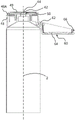
图1以总图示示出了按本发明的乳液分配器;Figure 1 shows a lotion dispenser according to the invention in a general diagram;
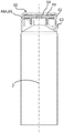
图2示出了按照图1的乳液分配器的分解图;Figure 2 shows an exploded view of the emulsion dispenser according to Figure 1;
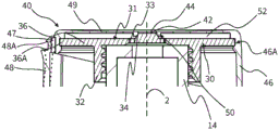
图3和3A以剖切的图示示出了乳液分配器在盖打开时的情况;Figures 3 and 3A show the lotion dispenser in a cutaway view with the lid open;
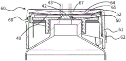
图4以剖切的图示示出了乳液分配器在盖关闭时的情况;Figure 4 shows the lotion dispenser in a cutaway view with the lid closed;
图5A和5B示出了为了封闭所述出料口的目的所述乳液分配器的铰链盖与将出料口包围的端面共同起作用的情况;Figures 5A and 5B show the situation in which the hinged lid of the emulsion dispenser cooperates with the end face surrounding the spout for the purpose of closing the spout;
图6和7示出了图1到5B的乳液分配器的变型方案,所述变型方案在铰链盖以及在所述铰链盖上所设置的封闭面的设计方面有别于前一种设计方案。FIGS. 6 and 7 show a variant of the emulsion dispenser of FIGS. 1 to 5B which differs from the previous design in terms of the design of the hinged cover and of the closing surface provided on the hinged cover.
具体实施方式Detailed ways
附图表明了按本发明的乳液分配器的构造。The drawings illustrate the construction of the emulsion dispenser according to the invention.
图1示出了所述乳液分配器10在交货状态中的情况。所述乳液分配器10包括液体储存器12,该液体储存器在此被构造为管子并且由此被设置用于通过手动的对外表面的压力加载来操纵。但是,原则上也能够考虑其他的、比如具有能移动的活塞的方案,所述活塞在端侧被推入到液体储存器中,以用于将液体从所述液体储存器中输送出来。Figure 1 shows the
在所述液体储存器12上比如借助于螺纹连接或者咬合连接安置了出料头20。所述出料头拥有基座,该基座在运行中相对于液体储存器基本上保持不动,并且所述出料头拥有铰链盖60,该铰链盖在关闭的状态中覆盖着出料口44并且能够借助于释放键48来去除卡锁并且打开。A
图2示出了所述乳液分配器10的单个组成部分。所述液体储存器12在图2的状态中还处于未被装填的状态中并且因此在其与排出管接头14对置的下端部上还未被封闭。FIG. 2 shows the individual components of the
如图2所表明的那样,所述出料头20具有两个构件30、40、也就是说内部构件30和外部构件40。所述内部构件在此设有较厚的壁体并且/或者由较硬的材料构成并且形成所述两个构件30、40中的较少能变形的构件。As shown in FIG. 2 , the
所述内部构件30在装配状态中固定地与所述外部构件40相连接。此外,所述内部构件具有连接管接头32,该连接管接头被构造用于借助于所提到的螺纹连接或者咬合连接来耦联在液体储存器12的排出管接头14上。所述排出管接头14在图示中在没有螺纹或咬合棱边的情况下简化地示出。In the assembled state, the
所述出料头及两个构件30、40的详细的构造可以从以下附图中看出。The detailed construction of the tap head and the two
图3和3A示出了所述出料头20处于准备好使用的打开的状态中的情况。可以看出,所述外部构件40具有侧壁46,端壁49在端侧连接到所述侧壁上。所述端壁49被排出通道42所贯穿,所述排出通道通入在出料口44中。所提到的端壁49在外侧几乎平坦地构成并且仅仅稍许凹入地拱起。所述外侧面在外侧没有加高部或凹处,因而由此能够将之前被排出到端壁上的乳液从这里涂到皮肤上。Figures 3 and 3A show the
所述侧壁46在释放键48的区域中设有缝隙47,该缝隙将释放健48在侧面并且向上与包围着的壁体分开并且由此允许所述释放健48的自由的可活动性。The
所述内部构件30为了共同形成阀压力室52而与所述外部构件40相连接。为此,在所述内部构件30的环形区段36的外圆周36A的区域中的外部的边缘卡入到所述外部构件40的侧壁46的内侧面上的槽中。这个接触区域形成本发明的意义上的固定区域46A。所述外部构件40和内部构件30的在固定区域46A中的连接按照规定不能松开并且是密封的。从液体储存器通过内部构件30中的液体穿孔33进入到阀压力室52中的液体由此只能通过出料口44来流出。The
所述贯穿端壁49的排出通道42以及居中地在内部构件30上所设置的截锥状的突起上的阀表面34一起形成排出阀50,该排出阀在静止状态中通过所述端壁49的稍许被预紧的形状来关闭。如果尤其通过对于所述管子的挤压来向液体储存器12中的液体加载压力,那么所述液体就在压力加载下进入到阀压力室52中并且引起端壁49的向外的变形。所述排出阀50由此被打开并且液体能够到达端壁49的外侧面上。如果足够多的液体被排出到端壁49上,那也能够直接从那里将其涂到皮肤上。The
如已经提到的那样,所述出料头20拥有铰链盖60。该铰链盖在这里所描述的设计方案中被构造为外部构件的一件式的部件并且借助于一件式地构成的铰链62以薄膜铰链的形式被连接到所述外部构件上。但是,作为替代方案,也能够考虑一种多构件的设计方案。As already mentioned, the
所述铰链盖60拥有稍许凹入地拱起的遮盖壁64,该遮盖壁的内侧面被构造得大于所述出料头的端壁49。所述遮盖壁64的内侧面被侧壁61所包围并且再其内侧没有任何伸出超过遮盖壁64的拱起的基本形状的突起。这引起的结果是,能够在这里容易地除去残余乳液。The hinged
为了打开所述铰链盖60而设置了已经描述的释放键48。在图4所示出的关闭的状态中,所述释放键的远侧的上端部上的卡锁棱边48A与铰链盖60上的相对应的卡锁棱边66卡锁在一起。因为所述盖在其遮盖壁64的区域中处于预应力下,所以所述卡锁结构在关闭的状态中相当牢固并且不用担心所述释放键48的无意的压入和所述铰链盖的打开。尽管如此,在手动地并且有意地操纵时,这种操纵能够以简单的并且在触觉上适意的方式来进行。通过所述缝隙47,所述释放键48在三侧自由切开并且由此能够容易地被压入。所述释放键48的太大幅度的压入通过以下方式来避免,即:所述释放键以在图3A中通过虚线来表明的方式碰到所述固定区域46A的外侧面。The
一旦通过压入而使所述卡锁棱边48A、66彼此脱去嵌合,所述铰链盖60就会弹开。通过所述遮盖壁64的区域中的预应力并且通过所述铰链的合适的被预紧的设计方案,能够在理想情况下实现这一点,即:仅仅通过对于释放键48的按压来实现图3的打开的状态,在所述打开的状态中所述铰链盖60偏转了大约180°。As soon as the latching edges 48A, 66 are disengaged from each other by pressing in, the hinged
图3在此表明一方面所述卡锁棱边48A、66以及另一方面所述铰链62的相对布置。关于主延伸方向2和关闭的状态,所述铰链62比所述卡锁棱边48A、66布置得明显更靠近液体储存器12,在图3的透视图中布置得更靠下面。关于主延伸方向在此大约为6mm的偏置引起以下结果,即:在打开的状态中所述卡锁棱边66离所述端壁49的外侧面的平面隔开的距离大于两倍、在此大约是13mm。FIG. 3 here shows the relative arrangement of the latching edges 48A, 66 on the one hand and the
这允许将之前被排出到外侧面上的乳液涂到皮肤上,而不存在以相当尖棱的卡锁棱边66接触到皮肤的危险。This allows the emulsion that was previously expelled on the outer side to be applied to the skin without the risk of contacting the skin with the rather sharp snap-on
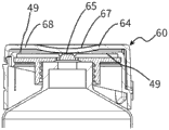
所述在关闭的状态中处于应力之下的铰链盖60借助于形成封闭面65的内侧面来封闭所述出料口44。这一点还要借助于图5A和5B再次进行详细解释。所述遮盖壁64的内侧面在其总体上直至侧面的侧壁61形成拱起的封闭面65,该封闭面具有在很大程度上统一的、大约12cm的弯曲半径。所述遮盖壁拥有统一的壁厚并且也在整个与封闭面65对置的外表面67上大致均匀地拱起。The hinged
在图5A的关闭的状态中,所述封闭面65在较小的环形的接触面43中抵靠在被出料口44贯穿的端壁49上并且由此附加于所述排出阀50来防止液体的流出。尤其对于所述管子12的无意的挤压以及所述阀压力室52中的压力升高也不可能导致液体通过出料口44来流出,因为所述排出阀50通过所述处于应力之下的遮盖壁64的封闭面65而被挤压到其关闭的位置。In the closed state of FIG. 5A , the closing
所述遮盖壁64的、具有统一的壁厚并且具有形成该遮盖壁64的整个内侧面的拱起的封闭面65的设计方案被视为是有利的,以用于获得所期望的关闭应力并且能够实现对于内侧面的容易的清洁。The design of the
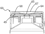
但是,也能够考虑作为替代方案的设计方案,在所述设计方案中所述拱起的封闭面65仅仅形成所述遮盖壁64的内侧面的中心的中间区域并且在外侧被比如平坦的或者反向拱起的环形区域所包围。图6和7示出了这样的设计方案。However, alternative designs are also conceivable, in which the
在图6的设计方案中设置了这样的平坦的环形区域68,该环形区域形成遮盖壁64的外部区域并且大致在半径的45%的范围内延伸。只有在所述环形区域的内侧设置了所述拱起的封闭面65,该封闭面相应地具有比前一种设计方案的封闭面稍小一点的弯曲半径。在这种设计方案中,所述弯曲半径大约为7cm。尽管对于由封闭面65和环形区域68所形成的内侧面的清洁不像在前一种设计方案中那样容易,但是按照图6的设计方案相对于已知的解决方案在技术上也是有利的。In the embodiment of FIG. 6 , a flat
在图7的设计方案中,所述遮盖壁64的内侧面也像在图6的设计方案中来形成。不过,与这种设计方案有差别的是,在这里没有设置统一的壁厚。在该设计方案中,所述遮盖壁64的与封闭面65对置的外侧面平坦地构成。这引起的结果是,在关闭所述铰链盖60并且该铰链盖在环形的接触面43的区域中抵靠在端壁49上时,主要在将封闭面65包围的较薄的环形区域68中进行变形。In the design of FIG. 7 , the inner side of the
Claims (14)
Applications Claiming Priority (3)
| Application Number | Priority Date | Filing Date | Title |
|---|---|---|---|
| EP18170634.2 | 2018-05-03 | ||
| EP18170634.2A EP3564147B1 (en) | 2018-05-03 | 2018-05-03 | Fluid dispenser with compressible fluid storage |
| PCT/EP2019/056444 WO2019211032A1 (en) | 2018-05-03 | 2019-03-14 | Liquid dispenser having compressible liquid store |
Publications (1)
| Publication Number | Publication Date |
|---|---|
| CN112041237A true CN112041237A (en) | 2020-12-04 |
Family
ID=62116272
Family Applications (1)
| Application Number | Title | Priority Date | Filing Date |
|---|---|---|---|
| CN201980030094.8A Pending CN112041237A (en) | 2018-05-03 | 2019-03-14 | Liquid dispenser with squeezable liquid reservoir |
Country Status (5)
| Country | Link |
|---|---|
| US (1) | US11661244B2 (en) |
| EP (2) | EP3564147B1 (en) |
| KR (1) | KR102563087B1 (en) |
| CN (1) | CN112041237A (en) |
| WO (1) | WO2019211032A1 (en) |
Families Citing this family (1)
| Publication number | Priority date | Publication date | Assignee | Title |
|---|---|---|---|---|
| KR102543259B1 (en) * | 2021-09-24 | 2023-06-14 | 김기철 | Improve type one touch cap of vessel |
Citations (10)
| Publication number | Priority date | Publication date | Assignee | Title |
|---|---|---|---|---|
| EP0253495A2 (en) * | 1986-07-14 | 1988-01-20 | Blairex Laboratories Inc. | Storage bottle for contact lens cleaning solution |
| US5246145A (en) * | 1990-05-03 | 1993-09-21 | Nalge Company | Liquid dropper spout having lockable pivoted closure cap |
| WO1999064313A1 (en) * | 1998-06-12 | 1999-12-16 | Bormioli Rocco & Figlio S.P.A. | A dispenser capsule for containers of liquid or semiliquid products |
| WO2001074687A1 (en) * | 2000-03-30 | 2001-10-11 | Kimberly-Clark Worldwide, Inc. | Wet wipe container with flexible orifice |
| US20030132240A1 (en) * | 2001-10-01 | 2003-07-17 | Gueret Jean-Louis H. | Device and method for dispensing a product |
| WO2004094239A2 (en) * | 2003-04-17 | 2004-11-04 | Portola Packaging Limited | Closure |
| FR2856984A1 (en) * | 2003-07-02 | 2005-01-07 | Janvier Sa | Pasty product e.g. sunscreen cream, dosage device, has cylindrical body of section greater than receptacle opening, and head with section increasing from body with maximum section being equal to opening diameter |
| WO2007024404A1 (en) * | 2005-08-25 | 2007-03-01 | Continentalafa Dispensing Company | Container closure with biased closed valve |
| DE102013214227A1 (en) * | 2013-07-19 | 2015-01-22 | Aptar Radolfzell Gmbh | Discharge device with closure |
| EP2923964A1 (en) * | 2014-03-25 | 2015-09-30 | Albéa le Tréport | System for dispensing a fluid product packaged in a tank |
Family Cites Families (26)
| Publication number | Priority date | Publication date | Assignee | Title |
|---|---|---|---|---|
| US1987156A (en) | 1932-11-18 | 1935-01-08 | William F Gilbert | Closure for collapsible tubes |
| FR996343A (en) | 1949-09-28 | 1951-12-18 | Screw cap for closing tubes, bottles and similar containers | |
| US3144964A (en) | 1961-03-17 | 1964-08-18 | American Can Co | Outsert for a collapsible tube |
| US4060179A (en) | 1972-05-02 | 1977-11-29 | Colgate-Palmolive Company | Collapsible tube structure |
| ZA732046B (en) | 1972-05-02 | 1974-11-27 | Colgate Palmolive Co | Collapsible tube |
| US4474314A (en) | 1982-06-29 | 1984-10-02 | Essex Chemical Corporation | Squeeze bottle self-closing viscous liquid dispensing valve having manually operated positive shut-off |
| FR2616756A1 (en) | 1987-06-19 | 1988-12-23 | Kerplas Snc | BLEACHING DEVICE FOR BOTTLE |
| FR2663291A1 (en) * | 1990-06-15 | 1991-12-20 | Oreal | PROCESS FOR THE PACKAGING OF A PRODUCT IN A BOTTLE, ENSURING A BETTER STORAGE OF THE PRODUCT DURING STORAGE AND CORRESPONDING PACKAGING PACKAGE. |
| AU2135795A (en) * | 1994-03-25 | 1995-10-17 | S Design Udo Suffa Gmbh | Closure |
| DE29709328U1 (en) | 1997-05-28 | 1997-08-14 | Georg Menshen GmbH & Co KG, 57413 Finnentrop | Two-part container closure |
| US7275665B2 (en) | 2000-12-14 | 2007-10-02 | Young John L | Vented fluid closure and container |
| US7328820B2 (en) * | 2000-12-14 | 2008-02-12 | John L. Young | Vented fluid closure and container |
| DE10157423A1 (en) | 2001-11-25 | 2003-06-05 | Roland Knauer | Container with elastic valve has valve between sealed shell and receiving shell, and sealing pin |
| US20030189065A1 (en) * | 2002-04-05 | 2003-10-09 | Gene Stull | Multi-piece snap-together cap |
| US8499985B2 (en) | 2003-05-28 | 2013-08-06 | Robert A. Lehmkuhl | Automatic dispensing cap for squeezable bottle |
| US20130193170A1 (en) * | 2003-05-28 | 2013-08-01 | Robert A. Lehmkuhl | Dispensing cap for a squeezeable bottle |
| CN1845856A (en) | 2003-09-02 | 2006-10-11 | 大塚制药株式会社 | Discharge member, discharge container having the discharge member, and instillation container |
| DE202004012821U1 (en) | 2004-08-12 | 2005-12-22 | Alpla-Werke Alwin Lehner Gmbh & Co. Kg | Fastener for bottle, has jar that is springly suspended and opened outwardly, membrane valve cooperating with jar and radially extending from edge of jar, and separate ventilation valve cooperating with opening in base of jar |
| SE530421C2 (en) | 2006-10-19 | 2008-06-03 | Petro Pack Ab | Packing valve for eg bottle or tube |
| KR20120032739A (en) | 2010-09-29 | 2012-04-06 | (주)연우 | Tube vessel with a one-touch cap having direction |
| FR2967141B1 (en) | 2010-11-04 | 2014-02-21 | Valois Sas | FLUID PRODUCT DISPENSING HEAD AND DISPENSER COMPRISING SUCH A DISPENSING HEAD. |
| KR200476920Y1 (en) * | 2013-03-27 | 2015-04-16 | 허성범 | The bottle cap |
| WO2015149160A1 (en) | 2014-04-04 | 2015-10-08 | Isλmi Vision Inc. | Valve closures |
| GB201601237D0 (en) * | 2016-01-22 | 2016-03-09 | Rieke Packaging Systems Ltd | Dispensing closures and dispensers |
| ES2673019T3 (en) | 2015-01-29 | 2018-06-19 | Aptar Radolfzell Gmbh | Discharge head |
| GB201601232D0 (en) * | 2016-01-22 | 2016-03-09 | Rieke Packaging Systems Ltd | Dispensing closures and dispensers |
-
2018
- 2018-05-03 EP EP18170634.2A patent/EP3564147B1/en active Active
-
2019
- 2019-03-14 US US17/052,340 patent/US11661244B2/en active Active
- 2019-03-14 WO PCT/EP2019/056444 patent/WO2019211032A1/en not_active Ceased
- 2019-03-14 CN CN201980030094.8A patent/CN112041237A/en active Pending
- 2019-03-14 KR KR1020207034721A patent/KR102563087B1/en active Active
- 2019-03-14 EP EP19711339.2A patent/EP3787983B1/en active Active
Patent Citations (10)
| Publication number | Priority date | Publication date | Assignee | Title |
|---|---|---|---|---|
| EP0253495A2 (en) * | 1986-07-14 | 1988-01-20 | Blairex Laboratories Inc. | Storage bottle for contact lens cleaning solution |
| US5246145A (en) * | 1990-05-03 | 1993-09-21 | Nalge Company | Liquid dropper spout having lockable pivoted closure cap |
| WO1999064313A1 (en) * | 1998-06-12 | 1999-12-16 | Bormioli Rocco & Figlio S.P.A. | A dispenser capsule for containers of liquid or semiliquid products |
| WO2001074687A1 (en) * | 2000-03-30 | 2001-10-11 | Kimberly-Clark Worldwide, Inc. | Wet wipe container with flexible orifice |
| US20030132240A1 (en) * | 2001-10-01 | 2003-07-17 | Gueret Jean-Louis H. | Device and method for dispensing a product |
| WO2004094239A2 (en) * | 2003-04-17 | 2004-11-04 | Portola Packaging Limited | Closure |
| FR2856984A1 (en) * | 2003-07-02 | 2005-01-07 | Janvier Sa | Pasty product e.g. sunscreen cream, dosage device, has cylindrical body of section greater than receptacle opening, and head with section increasing from body with maximum section being equal to opening diameter |
| WO2007024404A1 (en) * | 2005-08-25 | 2007-03-01 | Continentalafa Dispensing Company | Container closure with biased closed valve |
| DE102013214227A1 (en) * | 2013-07-19 | 2015-01-22 | Aptar Radolfzell Gmbh | Discharge device with closure |
| EP2923964A1 (en) * | 2014-03-25 | 2015-09-30 | Albéa le Tréport | System for dispensing a fluid product packaged in a tank |
Also Published As
| Publication number | Publication date |
|---|---|
| US11661244B2 (en) | 2023-05-30 |
| US20210237940A1 (en) | 2021-08-05 |
| EP3564147A1 (en) | 2019-11-06 |
| EP3787983B1 (en) | 2023-09-06 |
| WO2019211032A1 (en) | 2019-11-07 |
| EP3787983A1 (en) | 2021-03-10 |
| EP3564147B1 (en) | 2020-12-16 |
| KR102563087B1 (en) | 2023-08-02 |
| KR20210008012A (en) | 2021-01-20 |
Similar Documents
| Publication | Publication Date | Title |
|---|---|---|
| US4830229A (en) | Pump chamber dispenser | |
| US6367668B1 (en) | Self-closing closure and closure membrane relating to same | |
| JP2006271984A (en) | Pressurized device with tilt valve | |
| US8875953B2 (en) | Pump for liquid or viscous product | |
| JP2006517858A (en) | Dispenser pump | |
| US20090302064A1 (en) | Elastomeric dispensing pump that can be made with as few as two components | |
| CN107405638B (en) | Pump dispenser with outlet valve | |
| BR112012000397B1 (en) | DISPENSING ACTUATOR FOR A CONTAINER THAT HAS A DISPENSING VALVE TO DISPENS A FLUENT PRODUCT | |
| JP2002037286A (en) | Cap with snap-acting hinge and packaging assembly with such cap | |
| JP7740877B2 (en) | Flip-top cap for dispensing flowable dental substances | |
| CN108698064A (en) | dispenser pump | |
| US20020175137A1 (en) | Dispensing cap with cover | |
| CA2680998A1 (en) | Fluid dispensers for personal use | |
| EP1851138B1 (en) | Cap for an aerosol container or a spray container | |
| MX2008013784A (en) | Closure with hinged lid for bottles and the like with an automatic lid opening system. | |
| CN1802220B (en) | Pump nozzle device and method for manufacturing the same | |
| KR102641567B1 (en) | Compressible dispenser for liquid products, especially cosmetic liquid products such as creams | |
| US20120097713A1 (en) | Spray through cap for a pressurised fluid container | |
| CN115461279A (en) | massage applicator | |
| US6715646B2 (en) | Tilting nozzle cap which can be allocated to a container | |
| RU2225817C2 (en) | Liquid container | |
| CN102458678A (en) | Fluid product dispenser | |
| CN112041237A (en) | Liquid dispenser with squeezable liquid reservoir | |
| CN101622179B (en) | Fluid product dispensing head | |
| EP1590096B1 (en) | Outlet device for a container or vessel |
Legal Events
| Date | Code | Title | Description |
|---|---|---|---|
| PB01 | Publication | ||
| PB01 | Publication | ||
| SE01 | Entry into force of request for substantive examination | ||
| SE01 | Entry into force of request for substantive examination |