CN112042012A - Electrode for lithium ion secondary battery - Google Patents
Electrode for lithium ion secondary battery Download PDFInfo
- Publication number
- CN112042012A CN112042012A CN201980028362.2A CN201980028362A CN112042012A CN 112042012 A CN112042012 A CN 112042012A CN 201980028362 A CN201980028362 A CN 201980028362A CN 112042012 A CN112042012 A CN 112042012A
- Authority
- CN
- China
- Prior art keywords
- active material
- ion secondary
- secondary battery
- lithium ion
- current collector
- Prior art date
- Legal status (The legal status is an assumption and is not a legal conclusion. Google has not performed a legal analysis and makes no representation as to the accuracy of the status listed.)
- Pending
Links
Images


Classifications
-
- H—ELECTRICITY
- H01—ELECTRIC ELEMENTS
- H01M—PROCESSES OR MEANS, e.g. BATTERIES, FOR THE DIRECT CONVERSION OF CHEMICAL ENERGY INTO ELECTRICAL ENERGY
- H01M4/00—Electrodes
- H01M4/02—Electrodes composed of, or comprising, active material
- H01M4/36—Selection of substances as active materials, active masses, active liquids
- H01M4/362—Composites
- H01M4/366—Composites as layered products
-
- H—ELECTRICITY
- H01—ELECTRIC ELEMENTS
- H01M—PROCESSES OR MEANS, e.g. BATTERIES, FOR THE DIRECT CONVERSION OF CHEMICAL ENERGY INTO ELECTRICAL ENERGY
- H01M4/00—Electrodes
- H01M4/02—Electrodes composed of, or comprising, active material
- H01M4/36—Selection of substances as active materials, active masses, active liquids
- H01M4/58—Selection of substances as active materials, active masses, active liquids of inorganic compounds other than oxides or hydroxides, e.g. sulfides, selenides, tellurides, halogenides or LiCoFy; of polyanionic structures, e.g. phosphates, silicates or borates
- H01M4/583—Carbonaceous material, e.g. graphite-intercalation compounds or CFx
- H01M4/587—Carbonaceous material, e.g. graphite-intercalation compounds or CFx for inserting or intercalating light metals
-
- H—ELECTRICITY
- H01—ELECTRIC ELEMENTS
- H01M—PROCESSES OR MEANS, e.g. BATTERIES, FOR THE DIRECT CONVERSION OF CHEMICAL ENERGY INTO ELECTRICAL ENERGY
- H01M4/00—Electrodes
- H01M4/02—Electrodes composed of, or comprising, active material
- H01M4/13—Electrodes for accumulators with non-aqueous electrolyte, e.g. for lithium-accumulators; Processes of manufacture thereof
- H01M4/131—Electrodes based on mixed oxides or hydroxides, or on mixtures of oxides or hydroxides, e.g. LiCoOx
-
- H—ELECTRICITY
- H01—ELECTRIC ELEMENTS
- H01M—PROCESSES OR MEANS, e.g. BATTERIES, FOR THE DIRECT CONVERSION OF CHEMICAL ENERGY INTO ELECTRICAL ENERGY
- H01M4/00—Electrodes
- H01M4/02—Electrodes composed of, or comprising, active material
- H01M4/13—Electrodes for accumulators with non-aqueous electrolyte, e.g. for lithium-accumulators; Processes of manufacture thereof
- H01M4/133—Electrodes based on carbonaceous material, e.g. graphite-intercalation compounds or CFx
-
- H—ELECTRICITY
- H01—ELECTRIC ELEMENTS
- H01M—PROCESSES OR MEANS, e.g. BATTERIES, FOR THE DIRECT CONVERSION OF CHEMICAL ENERGY INTO ELECTRICAL ENERGY
- H01M4/00—Electrodes
- H01M4/02—Electrodes composed of, or comprising, active material
- H01M4/36—Selection of substances as active materials, active masses, active liquids
- H01M4/48—Selection of substances as active materials, active masses, active liquids of inorganic oxides or hydroxides
- H01M4/50—Selection of substances as active materials, active masses, active liquids of inorganic oxides or hydroxides of manganese
- H01M4/505—Selection of substances as active materials, active masses, active liquids of inorganic oxides or hydroxides of manganese of mixed oxides or hydroxides containing manganese for inserting or intercalating light metals, e.g. LiMn2O4 or LiMn2OxFy
-
- H—ELECTRICITY
- H01—ELECTRIC ELEMENTS
- H01M—PROCESSES OR MEANS, e.g. BATTERIES, FOR THE DIRECT CONVERSION OF CHEMICAL ENERGY INTO ELECTRICAL ENERGY
- H01M4/00—Electrodes
- H01M4/02—Electrodes composed of, or comprising, active material
- H01M4/36—Selection of substances as active materials, active masses, active liquids
- H01M4/48—Selection of substances as active materials, active masses, active liquids of inorganic oxides or hydroxides
- H01M4/52—Selection of substances as active materials, active masses, active liquids of inorganic oxides or hydroxides of nickel, cobalt or iron
- H01M4/525—Selection of substances as active materials, active masses, active liquids of inorganic oxides or hydroxides of nickel, cobalt or iron of mixed oxides or hydroxides containing iron, cobalt or nickel for inserting or intercalating light metals, e.g. LiNiO2, LiCoO2 or LiCoOxFy
-
- H—ELECTRICITY
- H01—ELECTRIC ELEMENTS
- H01M—PROCESSES OR MEANS, e.g. BATTERIES, FOR THE DIRECT CONVERSION OF CHEMICAL ENERGY INTO ELECTRICAL ENERGY
- H01M4/00—Electrodes
- H01M4/02—Electrodes composed of, or comprising, active material
- H01M4/64—Carriers or collectors
- H01M4/66—Selection of materials
- H01M4/661—Metal or alloys, e.g. alloy coatings
-
- H—ELECTRICITY
- H01—ELECTRIC ELEMENTS
- H01M—PROCESSES OR MEANS, e.g. BATTERIES, FOR THE DIRECT CONVERSION OF CHEMICAL ENERGY INTO ELECTRICAL ENERGY
- H01M4/00—Electrodes
- H01M4/02—Electrodes composed of, or comprising, active material
- H01M4/64—Carriers or collectors
- H01M4/70—Carriers or collectors characterised by shape or form
- H01M4/80—Porous plates, e.g. sintered carriers
-
- H—ELECTRICITY
- H01—ELECTRIC ELEMENTS
- H01M—PROCESSES OR MEANS, e.g. BATTERIES, FOR THE DIRECT CONVERSION OF CHEMICAL ENERGY INTO ELECTRICAL ENERGY
- H01M10/00—Secondary cells; Manufacture thereof
- H01M10/05—Accumulators with non-aqueous electrolyte
- H01M10/052—Li-accumulators
- H01M10/0525—Rocking-chair batteries, i.e. batteries with lithium insertion or intercalation in both electrodes; Lithium-ion batteries
-
- H—ELECTRICITY
- H01—ELECTRIC ELEMENTS
- H01M—PROCESSES OR MEANS, e.g. BATTERIES, FOR THE DIRECT CONVERSION OF CHEMICAL ENERGY INTO ELECTRICAL ENERGY
- H01M4/00—Electrodes
- H01M4/02—Electrodes composed of, or comprising, active material
- H01M2004/021—Physical characteristics, e.g. porosity, surface area
-
- H—ELECTRICITY
- H01—ELECTRIC ELEMENTS
- H01M—PROCESSES OR MEANS, e.g. BATTERIES, FOR THE DIRECT CONVERSION OF CHEMICAL ENERGY INTO ELECTRICAL ENERGY
- H01M4/00—Electrodes
- H01M4/02—Electrodes composed of, or comprising, active material
- H01M4/36—Selection of substances as active materials, active masses, active liquids
- H01M4/38—Selection of substances as active materials, active masses, active liquids of elements or alloys
- H01M4/386—Silicon or alloys based on silicon
-
- H—ELECTRICITY
- H01—ELECTRIC ELEMENTS
- H01M—PROCESSES OR MEANS, e.g. BATTERIES, FOR THE DIRECT CONVERSION OF CHEMICAL ENERGY INTO ELECTRICAL ENERGY
- H01M4/00—Electrodes
- H01M4/02—Electrodes composed of, or comprising, active material
- H01M4/36—Selection of substances as active materials, active masses, active liquids
- H01M4/48—Selection of substances as active materials, active masses, active liquids of inorganic oxides or hydroxides
- H01M4/483—Selection of substances as active materials, active masses, active liquids of inorganic oxides or hydroxides for non-aqueous cells
-
- H—ELECTRICITY
- H01—ELECTRIC ELEMENTS
- H01M—PROCESSES OR MEANS, e.g. BATTERIES, FOR THE DIRECT CONVERSION OF CHEMICAL ENERGY INTO ELECTRICAL ENERGY
- H01M4/00—Electrodes
- H01M4/02—Electrodes composed of, or comprising, active material
- H01M4/64—Carriers or collectors
- H01M4/70—Carriers or collectors characterised by shape or form
- H01M4/80—Porous plates, e.g. sintered carriers
- H01M4/808—Foamed, spongy materials
-
- Y—GENERAL TAGGING OF NEW TECHNOLOGICAL DEVELOPMENTS; GENERAL TAGGING OF CROSS-SECTIONAL TECHNOLOGIES SPANNING OVER SEVERAL SECTIONS OF THE IPC; TECHNICAL SUBJECTS COVERED BY FORMER USPC CROSS-REFERENCE ART COLLECTIONS [XRACs] AND DIGESTS
- Y02—TECHNOLOGIES OR APPLICATIONS FOR MITIGATION OR ADAPTATION AGAINST CLIMATE CHANGE
- Y02E—REDUCTION OF GREENHOUSE GAS [GHG] EMISSIONS, RELATED TO ENERGY GENERATION, TRANSMISSION OR DISTRIBUTION
- Y02E60/00—Enabling technologies; Technologies with a potential or indirect contribution to GHG emissions mitigation
- Y02E60/10—Energy storage using batteries
Landscapes
- Chemical & Material Sciences (AREA)
- Chemical Kinetics & Catalysis (AREA)
- Electrochemistry (AREA)
- General Chemical & Material Sciences (AREA)
- Engineering & Computer Science (AREA)
- Materials Engineering (AREA)
- Inorganic Chemistry (AREA)
- Composite Materials (AREA)
- Manufacturing & Machinery (AREA)
- Battery Electrode And Active Subsutance (AREA)
- Cell Electrode Carriers And Collectors (AREA)
- Secondary Cells (AREA)
Abstract
提供一种能够在用于锂离子二次电池时获得优异的充放电循环特性的锂离子二次电池用电极。锂离子二次电池用电极包括:由具有柱状骨架以三维相连而形成的三维网眼状构造的金属多孔体构成的集电体;保持于所述集电体的一个面上的第1活性物质;和保持于所述集电体的另一个面上的第2活性物质。
An electrode for a lithium-ion secondary battery is provided, which can achieve excellent charge-discharge cycle characteristics when used in a lithium-ion secondary battery. The electrode for a lithium-ion secondary battery includes: a current collector composed of a three-dimensional mesh-like structure of a metal porous body having a columnar framework connected in three dimensions; a first active material held on one surface of the current collector; and a second active material held on the other surface of the current collector.
Description
技术领域technical field
本发明涉及锂离子二次电池用电极。The present invention relates to an electrode for a lithium ion secondary battery.
背景技术Background technique
以往,已知一种锂离子二次电池用电极,其具备活性物质的粒径不同的两层活性物质层,且两层活性物质层的厚度分别在20~30μm的范围内(例如参照专利文献1)。Conventionally, an electrode for a lithium ion secondary battery is known which includes two active material layers having different particle diameters of the active material, and the thicknesses of the two active material layers are in the range of 20 to 30 μm (for example, refer to Patent Documents). 1).
根据专利文献1记载的锂离子二次电池用电极,在使用该电极的锂离子二次电池中,能够不使能量密度降低地提高输出密度。According to the electrode for lithium ion secondary batteries described in Patent Document 1, in the lithium ion secondary battery using the electrode, the output density can be increased without lowering the energy density.
现有技术文献prior art literature
专利文献Patent Literature
专利文献1:日本特开2002-151055号公报Patent Document 1: Japanese Patent Laid-Open No. 2002-151055
发明内容SUMMARY OF THE INVENTION
然而,就专利文献1记载的锂离子二次电池用电极而言,由于上述两层活性物质层的膨胀收缩率不同,所以在用于锂离子二次电池时,若反复以高速率进行充放电,则存在容易在两个活性物质层的界面发生滑落、充放电循环特性下降的不良情况。However, the electrode for a lithium ion secondary battery described in Patent Document 1 has different expansion and shrinkage ratios of the two active material layers, so when it is used in a lithium ion secondary battery, if charge and discharge are repeated at a high rate , there is a disadvantage that slippage is likely to occur at the interface of the two active material layers, and the charge-discharge cycle characteristics are degraded.
本发明的目的在于,消除上述不良情况,提供一种具备两种活性物质的锂离子二次电池用电极,且该锂离子二次电池用电极能够在用于锂离子二次电池时获得优异的充放电循环特性。An object of the present invention is to eliminate the above-mentioned disadvantages, and to provide an electrode for a lithium ion secondary battery including two active materials, and which can obtain an excellent electrode for a lithium ion secondary battery when used in a lithium ion secondary battery. Charge-discharge cycle characteristics.
为了达成上述目的,本发明的锂离子二次电池用电极的特征在于,包括:由具有三维网眼状构造的金属多孔体构成的集电体;保持于上述集电体的一个面上的第1活性物质;和保持于上述集电体的另一个面上的第2活性物质。In order to achieve the above object, the electrode for a lithium ion secondary battery of the present invention is characterized by comprising: a current collector composed of a metal porous body having a three-dimensional mesh structure; a first current collector held on one surface of the current collector an active material; and a second active material held on the other surface of the current collector.
本发明的锂离子二次电池用电极中,由于在上述集电体的一个面上保持有第1活性物质、并在上述集电体的另一个面上保持有第2活性物质,所以即使在用于锂离子二次电池时,也能抑制在第1活性物质与第2活性物质的界面发生滑落。因此,本发明的锂离子二次电池用电极能够在用于锂离子二次电池时获得优异的充放电循环特性。In the electrode for lithium ion secondary batteries of the present invention, since the first active material is held on one surface of the current collector and the second active material is held on the other surface of the current collector, even in the When used in a lithium ion secondary battery, slippage at the interface between the first active material and the second active material can be suppressed. Therefore, the electrode for lithium ion secondary batteries of the present invention can obtain excellent charge-discharge cycle characteristics when used in a lithium ion secondary battery.
在本发明的锂离子二次电池用电极中,优选地,上述第1活性物质包含高容量型活性物质,上述第2活性物质包含高输出型活性物质。本发明的锂离子二次电池用电极中,由于上述第1活性物质包含高容量型活性物质、且上述第2活性物质包含高输出型活性物质,所以能够同时提高能量密度和输出密度双方。In the electrode for a lithium ion secondary battery of the present invention, preferably, the first active material includes a high-capacity active material, and the second active material includes a high-output active material. In the electrode for a lithium ion secondary battery of the present invention, since the first active material includes a high-capacity active material and the second active material includes a high-output active material, both energy density and output density can be improved at the same time.
另外,本发明的锂离子二次电池用电极优选为,在上述第1活性物质包含高容量型活性物质、且上述第2活性物质包含高输出型活性物质时,保持于上述集电体的一个面上的第1活性物质的厚度比保持于上述集电体的另一个面上的第2活性物质的厚度厚。根据本发明的锂离子二次电池用电极,由于上述第1活性物质的厚度比上述第2活性物质的厚度厚,所以能够在不损害该第2活性物质的输出密度的情况下提高作为电极整体的容量,还能提高能量密度。Further, in the electrode for lithium ion secondary battery of the present invention, when the first active material includes a high-capacity active material and the second active material includes a high-power active material, it is preferable to be held in one of the current collectors The thickness of the first active material on one surface is thicker than the thickness of the second active material held on the other surface of the current collector. According to the electrode for a lithium ion secondary battery of the present invention, since the thickness of the first active material is thicker than the thickness of the second active material, the output density of the second active material can be improved as a whole electrode without impairing the output density of the second active material. capacity and increase energy density.
另外,本发明的锂离子二次电池用电极能够将上述高容量型活性物质设为从由Li(Ni5/10Co2/10Mn3/10)O2、Li(Ni6/10Co2/10Mn2/10)O2、Li(Ni8/10Co1/10Mn1/10)O2、Li(Ni0.8Co0.15Al0.05)O2构成的组中选择的一种复合金属氧化物,并将上述高输出型活性物质设为从由Li(Ni1/ 6Co4/6Mn1/6)O2、Li(Ni1/3Co1/3Mn1/3)O2构成的组中选择的一种复合金属氧化物。In addition, in the electrode for lithium ion secondary battery of the present invention, the above-mentioned high-capacity active material can be composed of Li(Ni 5/10 Co 2/10 Mn 3/10 )O 2 , Li(Ni 6/10 Co 2 ) Oxidation of a composite metal selected from the group consisting of /10 Mn 2/10 )O 2 , Li(Ni 8/10 Co 1/10 Mn 1/10 )O 2 , and Li(Ni 0.8 Co 0.15 Al 0.05 )O 2 material, and the above-mentioned high-power active material is made of Li(Ni 1/6 Co 4/6 Mn 1/6 )O 2 and Li(Ni 1/3 Co 1/3 Mn 1/3 ) O 2 A composite metal oxide selected from the group of .
另外,本发明的锂离子二次电池用电极也可以将上述高容量型活性物质设为从由人造石墨、天然石墨、Si、SiO构成的组中选择的一种材料,并将上述高输出型活性物质设为硬碳。In addition, the electrode for a lithium ion secondary battery of the present invention may include the above-mentioned high-capacity type active material as one material selected from the group consisting of artificial graphite, natural graphite, Si, and SiO, and the above-mentioned high-power type active material may be used. The active material was set to hard carbon.
本发明的锂离子二次电池用电极通过使用上述任一种的上述高容量型活性物质与上述高输出型活性物质的组合,能够更可靠地同时提高能量密度和输出密度。The electrode for a lithium ion secondary battery of the present invention can more reliably improve both the energy density and the output density by using a combination of the high-capacity active material and the high-output active material described above.
附图说明Description of drawings
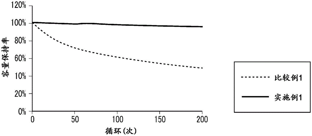
图1是表示使用本发明的一个实施方式的电极的锂离子二次电池中的容量保持率相对于循环次数的变化的图表。FIG. 1 is a graph showing a change in the capacity retention rate with respect to the number of cycles in a lithium ion secondary battery using an electrode according to an embodiment of the present invention.
图2是表示使用本发明的一个实施方式的电极的锂离子二次电池中的内部电阻相对于循环次数的变化的图表。2 is a graph showing changes in internal resistance with respect to the number of cycles in a lithium ion secondary battery using the electrode according to the embodiment of the present invention.
图3是表示使用本发明的一个实施方式的电极的锂离子二次电池中的能量密度的图表。3 is a graph showing the energy density in a lithium ion secondary battery using the electrode according to the embodiment of the present invention.
图4是表示使用本发明的一个实施方式的电极的锂离子二次电池中的输出密度的图表。4 is a graph showing the output density in a lithium ion secondary battery using the electrode of one embodiment of the present invention.
图5是表示使用本发明的另一实施方式的电极的锂离子二次电池中的容量保持率相对于循环次数的变化的图表。5 is a graph showing a change in the capacity retention rate with respect to the number of cycles in a lithium ion secondary battery using an electrode according to another embodiment of the present invention.
图6是表示使用本发明的另一实施方式的电极的锂离子二次电池中的内部电阻相对于循环次数的变化的图表。6 is a graph showing changes in internal resistance with respect to the number of cycles in a lithium ion secondary battery using an electrode according to another embodiment of the present invention.
图7是表示使用本发明的另一实施方式的电极的锂离子二次电池中的能量密度的图表。7 is a graph showing energy density in a lithium ion secondary battery using an electrode according to another embodiment of the present invention.
图8是表示使用本发明的另一实施方式的电极的锂离子二次电池中的输出密度的图表。8 is a graph showing the output density in a lithium ion secondary battery using an electrode according to another embodiment of the present invention.
具体实施方式Detailed ways
接着,参照附图对本发明的实施方式进行更详细的说明。Next, embodiments of the present invention will be described in more detail with reference to the accompanying drawings.
本实施方式的锂离子二次电池用电极包括:由具有三维网眼状构造的金属多孔体构成的集电体;保持于上述集电体的一个面上的第1活性物质;和保持于上述集电体的另一个面上的第2活性物质。The electrode for a lithium ion secondary battery of the present embodiment includes: a current collector composed of a metal porous body having a three-dimensional mesh structure; a first active material held on one surface of the current collector; and a current collector held on the above-mentioned collector The second active material on the other surface of the electric body.
上述金属多孔体例如能够由铝、镍、铜、不锈钢、钛等具备导电性的金属构成,且适合使用气孔率为90~98%、空孔(网眼)数为46~50个/英寸、空孔径为0.4~0.6mm、比表面积为4500~5500m2/m3、厚度为0.8~1.2mm的金属多孔体。上述金属多孔体在作为正极集电体的情况下优选由铝构成,在作为负极集电体的情况下优选由铜构成。The above-mentioned porous metal body can be made of, for example, a metal having electrical conductivity such as aluminum, nickel, copper, stainless steel, and titanium, and is suitable for use with a porosity of 90 to 98%, a number of pores (mesh) of 46 to 50 per inch, and a porosity of 90 to 98%. A porous metal body having a pore diameter of 0.4 to 0.6 mm, a specific surface area of 4500 to 5500 m 2 /m 3 , and a thickness of 0.8 to 1.2 mm. The above-mentioned porous metal body is preferably composed of aluminum when used as a positive electrode current collector, and preferably composed of copper when used as a negative electrode current collector.
上述金属多孔体在由铝构成的情况下,能够通过以下方式制造:在将碳涂料涂敷到具有连续气泡的聚氨酯发泡体并进行导电化处理之后,使用以33﹕67的摩尔比含有氯化1-乙基-3-甲基咪唑和氯化铝(AlCl3)且还含有少量邻二氮菲的电镀液,在非活性环境气体中进行电镀从而形成规定量的铝层,在500~660℃范围的温度下的含氧环境气体中,在抑制铝表面过度氧化的条件下使聚氨酯发泡体和碳涂料热分解而将其除去。另外,上述金属多孔体在由铜构成的情况下,能够通过以下方式制造:将碳涂料涂敷到具有连续气泡的聚氨酯发泡体并进行导电化处理,通过电镀而形成规定量的铜层,在使聚氨酯发泡体和碳涂料热分解而将其除去之后,将氧化后的铜层在氢气环境下进行还原处理。作为以此方式制造的金属多孔体,能够使用住友电气工业株式会社制的“Aluminum-Celmet”(注册商标)和铜或镍的“Celmet”(注册商标)。When the above-mentioned porous metal body is made of aluminum, it can be produced by applying a carbon coating material to a polyurethane foam having open cells and conducting conductive treatment, and then using a method containing chlorine in a molar ratio of 33:67. The electroplating solution containing 1-ethyl-3-methylimidazole and aluminum chloride (AlCl 3 ) and also containing a small amount of phenanthroline is electroplated in an inert ambient gas to form a predetermined amount of aluminum layer. In an oxygen-containing ambient gas at a temperature in the range of 660°C, the polyurethane foam and the carbon paint are thermally decomposed and removed under conditions that suppress excessive oxidation of the aluminum surface. In addition, when the metal porous body is made of copper, it can be produced by applying a carbon coating material to a polyurethane foam having open cells, conducting a conductive treatment, and forming a predetermined amount of copper layer by electroplating, After the urethane foam and the carbon paint are thermally decomposed and removed, the oxidized copper layer is subjected to reduction treatment in a hydrogen atmosphere. As the porous metal body produced in this way, "Aluminum-Celmet" (registered trademark) manufactured by Sumitomo Electric Industries, Ltd. and "Celmet" (registered trademark) of copper or nickel can be used.
在上述锂离子二次电池用电极中,上述第1活性物质能够包含高容量型活性物质,上述第2活性物质能够包含高输出型活性物质。另外,在上述锂离子二次电池用电极中,保持于上述集电体的一个面上的第1活性物质的厚度优选比保持于上述集电体的另一个面上的第2活性物质的厚度厚。在该情况下,具体而言,上述第1活性物质优选设为100~250μm范围的厚度,上述第2活性物质优选设为50~150μm范围的厚度。In the electrode for a lithium ion secondary battery, the first active material may include a high-capacity active material, and the second active material may include a high-power active material. In the above-mentioned electrode for a lithium ion secondary battery, the thickness of the first active material held on one surface of the current collector is preferably larger than the thickness of the second active material held on the other surface of the current collector thick. In this case, specifically, the first active material preferably has a thickness in the range of 100 to 250 μm, and the second active material preferably has a thickness in the range of 50 to 150 μm.
在本实施方式的锂离子二次电池用电极中,上述高容量型活性物质例如能够使用从由Li(Ni5/10Co2/10Mn3/10)O2、Li(Ni6/10Co2/10Mn2/10)O2、Li(Ni8/10Co1/10Mn1/10)O2、Li(Ni0.8Co0.15Al0.05)O2构成的组中选择的至少一种复合金属氧化物。在该情况下,上述高输出型活性物质例如也能使用从由Li(Ni1/6Co4/6Mn1/6)O2、Li(Ni1/3Co1/3Mn1/3)O2、LiCoO2、LiNiO2构成的组中选择的至少一种复合金属氧化物。In the electrode for a lithium ion secondary battery of the present embodiment, the high-capacity active material can be used, for example, from Li(Ni 5/10 Co 2/10 Mn 3/10 )O 2 , Li(Ni 6/10 Co At least one compound selected from the group consisting of 2/10 Mn 2/10 )O 2 , Li(Ni 8/10 Co 1/10 Mn 1/10 )O 2 , and Li(Ni 0.8 Co 0.15 Al 0.05 )O 2 Metal oxide. In this case, the above-mentioned high-power active material can also be used, for example, from Li(Ni 1/6 Co 4/6 Mn 1/6 )O 2 , Li(Ni 1/3 Co 1/3 Mn 1/3 ) At least one composite metal oxide selected from the group consisting of O 2 , LiCoO 2 , and LiNiO 2 .
另外,上述高容量型活性物质例如能够使用从由人造石墨、天然石墨、Si、SiO构成的组中选择的至少一种材料。在该情况下,上述高输出型活性物质例如能够使用从由硬碳和软碳构成的组中选择的至少一种材料。In addition, as the high-capacity active material, at least one material selected from the group consisting of artificial graphite, natural graphite, Si, and SiO can be used, for example. In this case, for example, at least one material selected from the group consisting of hard carbon and soft carbon can be used as the high-output active material.
接着,对本实施方式的锂离子二次电池用电极的制造方法进行说明。Next, the manufacturing method of the electrode for lithium ion secondary batteries of this embodiment is demonstrated.
在本实施方式的锂离子二次电池用电极是锂离子二次电池的正极的情况下,首先,将作为高容量型活性物质的从由Li(Ni5/10Co2/10Mn3/10)O2、Li(Ni6/10Co2/10Mn2/10)O2、Li(Ni8/10Co1/10Mn1/10)O2、Li(Ni0.8Co0.15Al0.05)O2构成的组中选择的一种复合金属氧化物、作为粘结剂的聚偏二氟乙烯(PVDF)、和作为导电助剂的炭黑,以高容量型活性物质﹕粘结剂﹕导电助剂=80~99﹕0.5~19.5﹕0.5~19.5的质量比且以总量成为100的方式混合,并利用N-甲基吡咯烷酮等有机溶剂进行稀释,由此制备第1活性物质用浆料。When the electrode for a lithium ion secondary battery of the present embodiment is a positive electrode of a lithium ion secondary battery, first, as a high-capacity type active material, from Li(Ni 5/10 Co 2/10 Mn 3/10 )O 2 , Li(Ni 6/10 Co 2/10 Mn 2/10 )O 2 , Li(Ni 8/10 Co 1/10 Mn 1/10 )O 2 , Li(Ni 0.8 Co 0.15 Al 0.05 )O A composite metal oxide selected from the group consisting of 2 , polyvinylidene fluoride (PVDF) as a binder, and carbon black as a conductive aid, in a high-capacity type active material: binder: conductive aid Agent = 80 to 99: 0.5 to 19.5: 0.5 to 19.5 in a mass ratio of 0.5 to 19.5, mixed so that the total amount would be 100, and diluted with an organic solvent such as N-methylpyrrolidone to prepare a slurry for the first active material.
接着,将作为高输出型活性物质的从由Li(Ni1/6Co4/6Mn1/6)O2、Li(Ni1/3Co1/3Mn1/3)O2构成的组中选择的一种复合金属氧化物、作为粘结剂的聚偏二氟乙烯(PVDF)、和作为导电助剂的炭黑,以高输出型活性物质﹕粘结剂﹕导电助剂=80~99﹕0.5~19.5﹕0.5~19.5的质量比且以总量成为100的方式混合,并利用N-甲基吡咯烷酮等有机溶剂进行稀释,由此制备第2活性物质用浆料。Next, as a high-power active material, a group consisting of Li(Ni 1/6 Co 4/6 Mn 1/6 )O 2 and Li(Ni 1/3 Co 1/3 Mn 1/3 )O 2 was used. A composite metal oxide selected from , polyvinylidene fluoride (PVDF) as a binder, and carbon black as a conductive assistant, with high output active material: binder: conductive assistant = 80~ 99:0.5-19.5:0.5-19.5 mass ratio and it mixed so that the total amount might become 100, and diluted with organic solvents, such as N-methylpyrrolidone, and prepared the slurry for 2nd active materials.
接着,将上述第1活性物质用浆料例如通过从喷嘴以规定压力挤出而涂敷到由上述金属多孔体构成的集电体的一个面上。接着,使涂敷有上述第1活性物质用浆料的由上述金属多孔体构成的集电体在大气中以90~130℃范围的温度干燥0.5~3个小时。接着,将上述第2活性物质用浆料例如通过从喷嘴以规定压力挤出而涂敷到由上述金属多孔体构成的集电体的另一个面上。Next, the above-mentioned slurry for the first active material is applied to one surface of the current collector composed of the above-mentioned porous metal body, for example, by extrusion from a nozzle at a predetermined pressure. Next, the current collector composed of the porous metal body to which the slurry for the first active material was applied is dried in the air at a temperature in the range of 90 to 130° C. for 0.5 to 3 hours. Next, the slurry for the second active material is applied to the other surface of the current collector composed of the porous metal body, for example, by extrusion from a nozzle at a predetermined pressure.
接着,使涂敷有上述第1活性物质用浆料和上述第2活性物质用浆料的由上述金属多孔体构成的集电体在大气中以90~130℃范围的温度干燥0.5~3个小时,形成保持于上述集电体的一个面上的第1活性物质和保持于另一个面上的第2活性物质,并以分别成为规定密度的方式进行辊压。然后,在真空中以110~130℃范围的温度干燥11~13个小时,由此制成正极。Next, 0.5 to 3 pieces of the current collector composed of the porous metal body to which the slurry for the first active material and the slurry for the second active material are applied are dried in the atmosphere at a temperature in the range of 90 to 130° C. When it is small, the first active material held on one surface of the current collector and the second active material held on the other surface are formed and rolled so that the respective densities become predetermined. Then, it is dried in a vacuum at a temperature in the range of 110 to 130° C. for 11 to 13 hours, thereby producing a positive electrode.
另外,在本实施方式的锂离子二次电池用电极是锂离子二次电池的负极的情况下,首先,将作为高容量型活性物质的从由人造石墨、天然石墨、Si、SiO构成的组中选择的一种材料、作为粘结剂的从由羧甲基纤维素、苯乙烯丁二烯橡胶、聚丙烯酸钠、聚偏二氟乙烯构成的组中选择的至少一种化合物、和作为导电助剂的炭黑,以高容量型活性物质﹕粘结剂﹕导电助剂=80~99.5﹕0~10﹕5~20的质量比且以总量成为100的方式混合,并利用N-甲基吡咯烷酮等有机溶剂或纯水进行稀释,由此制备第1活性物质用浆料。In addition, when the electrode for lithium ion secondary batteries of the present embodiment is a negative electrode of a lithium ion secondary battery, first, as a high-capacity type active material, a group consisting of artificial graphite, natural graphite, Si, and SiO is used. A material selected from, at least one compound selected from the group consisting of carboxymethyl cellulose, styrene butadiene rubber, sodium polyacrylate, polyvinylidene fluoride as a binder, and as a conductive The carbon black of the auxiliary agent is mixed in a mass ratio of high-capacity active material: binder: conductive auxiliary agent = 80-99.5: 0-10: 5-20, and the total amount is 100, and N-formaldehyde is used. The slurry for the first active material is prepared by diluting with an organic solvent such as pyrrolidone or pure water.
接着,将作为高输出型活性物质的硬碳、作为粘结剂的从由羧甲基纤维素、苯乙烯丁二烯橡胶、聚丙烯酸钠、聚偏二氟乙烯构成的组中选择的至少一种化合物、和作为导电助剂的炭黑,以高容量型活性物质﹕粘结剂﹕导电助剂=80~99.5﹕0~10﹕5~20的质量比并以总量成为100的方式混合,并利用N-甲基吡咯烷酮等有机溶剂或纯水进行稀释,由此制备第2活性物质用浆料。Next, at least one selected from the group consisting of carboxymethyl cellulose, styrene butadiene rubber, sodium polyacrylate, and polyvinylidene fluoride is used as a hard carbon as a high-output active material and as a binder. A compound, and carbon black as a conductive aid are mixed in a mass ratio of high-capacity active material: binder: conductive aid = 80 to 99.5: 0 to 10: 5 to 20 so that the total amount becomes 100 , and diluted with an organic solvent such as N-methylpyrrolidone or pure water to prepare a slurry for the second active material.
接着,除了取代制备为正极用的上述第1活性物质用浆料和上述第2活性物质用浆料而使用制备为负极用的上述第1活性物质用浆料和上述第2活性物质用浆料以外,与正极的情况完全相同地,在由上述金属多孔体构成的集电体上进行涂敷,在大气中进行干燥之后进行辊压,并进一步在真空中进行干燥,由此制成负极。Next, in place of the slurry for the first active material and the slurry for the second active material prepared for the positive electrode, the slurry for the first active material and the slurry for the second active material prepared for the negative electrode were used instead of the slurry for the first active material and the slurry for the second active material. Other than that, in exactly the same manner as in the case of the positive electrode, the current collector composed of the above-mentioned porous metal body was coated, dried in the air, and then rolled, and further dried in a vacuum to prepare a negative electrode.
本实施方式的锂离子二次电池能够通过以下方式制造:将上述锂离子二次电池用电极作为正极或负极,在正极与负极之间夹着隔膜(separator),使电解液含浸于该隔膜,之后将容器密封。The lithium ion secondary battery of the present embodiment can be produced by using the above-mentioned electrode for lithium ion secondary batteries as a positive electrode or a negative electrode, sandwiching a separator between the positive electrode and the negative electrode, and impregnating the separator with an electrolytic solution, The container is then sealed.
在本实施方式的锂离子二次电池中,当将上述锂离子二次电池用电极设为正极时,作为负极活性物质例如能够使用石墨、硬碳、软碳、Si、SiO、金属锂等。另一方面,当将上述锂离子二次电池用电极设为负极时,作为正极活性物质例如能够使用Li(Ni5/10Co2/ 10Mn3/10)O2、Li(Ni6/10Co2/10Mn2/10)O2、Li(Ni8/10Co1/10Mn1/10)O2、Li(Ni0.8Co0.15Al0.05)O2、Li(Ni1/6Co4/6Mn1/6)O2、Li(Ni1/3Co1/3Mn1/3)O2、LiCoO2、LiNiO2、LiMnO2、LiMn2O4等。In the lithium ion secondary battery of the present embodiment, when the above-mentioned electrode for lithium ion secondary batteries is used as a positive electrode, graphite, hard carbon, soft carbon, Si, SiO, metallic lithium, etc. can be used as the negative electrode active material, for example. On the other hand, when the above-mentioned electrode for lithium ion secondary batteries is used as a negative electrode, as the positive electrode active material, for example, Li(Ni 5/10 Co 2/ 10 Mn 3/10 )O 2 , Li(Ni 6/10 ) can be used. Co 2/10 Mn 2/10 )O 2 , Li(Ni 8/10 Co 1/10 Mn 1/10 )O 2 , Li(Ni 0.8 Co 0.15 Al 0.05 )O 2 , Li(Ni 1/6 Co 4 /6 Mn 1/6 )O 2 , Li(Ni 1/3 Co 1/3 Mn 1/3 )O 2 , LiCoO 2 , LiNiO 2 , LiMnO 2 , LiMn 2 O 4 and the like.
另外,作为上述隔膜,例如能够使用由聚乙烯、聚丙烯等构成的微多孔性膜。Moreover, as said separator, the microporous film which consists of polyethylene, polypropylene, etc. can be used, for example.
另外,作为上述电解液,例如能够使用在碳酸乙烯酯、碳酸亚丙酯、碳酸二甲酯、碳酸二乙酯、碳酸甲乙酯等溶剂中以0.1~3mol/L范围的浓度、优选以0.6~1.5mol/L范围的浓度溶解有LiPF6、LiBF4、LiClO4等支持电解质而得到的电解液。In addition, as the electrolytic solution, for example, it can be used in a solvent such as ethylene carbonate, propylene carbonate, dimethyl carbonate, diethyl carbonate, and ethyl methyl carbonate at a concentration in the range of 0.1 to 3 mol/L, preferably at a concentration of 0.6 mol/L. An electrolyte solution obtained by dissolving supporting electrolytes such as LiPF 6 , LiBF 4 , and LiClO 4 in a concentration in the range of to 1.5 mol/L.
接着,示出本发明的实施例及比较例。Next, Examples and Comparative Examples of the present invention are shown.
实施例Example
〔实施例1〕[Example 1]
在本实施例中,首先,作为由具有柱状骨架以三维相连而形成的三维网眼状构造的金属多孔体构成的集电体(以下简称为“三维骨架集电体”),使用由铝构成且气孔率为95%、空孔(网眼)数为46~50个/英寸、空孔径为0.5mm、比表面积为5000m2/m3、厚度为1.0mm、纵150mm、横200mm的集电体(住友电气工业株式会社制Celmet(注册商标)),以如下方式制作了正极。In the present Example, first, as a current collector composed of a metal porous body having a three-dimensional mesh structure in which columnar skeletons are three-dimensionally connected (hereinafter simply referred to as "three-dimensional skeleton current collector"), a current collector composed of aluminum and The porosity is 95%, the number of holes (mesh) is 46 to 50 per inch, the hole diameter is 0.5mm, the specific surface area is 5000m 2 /m 3 , the thickness is 1.0mm, the length is 150mm, and the width is 200mm. The collector ( Celmet (registered trademark), manufactured by Sumitomo Electric Industries, Ltd., produced the positive electrode as follows.
首先,在上述三维骨架集电体的一个面的中央部的纵80mm、横150mm的区域内涂敷了包含高容量型正极活性物质的第1正极活性物质用浆料。接着,在上述三维骨架集电体的另一个面的与涂敷有上述第1正极活性物质用浆料的区域对应的区域内,涂敷了包含高输出型正极活性物质的第2正极活性物质用浆料。First, a first positive electrode active material slurry containing a high-capacity positive electrode active material was applied to an area of 80 mm in length and 150 mm in width at the center of one surface of the three-dimensional skeleton current collector. Next, in the region corresponding to the region where the slurry for the first positive electrode active material was applied on the other surface of the three-dimensional skeleton current collector, a second positive electrode active material containing a high output positive electrode active material was applied Use slurry.
上述第1正极活性物质用浆料是通过以下方式制备的:将作为高容量型活性物质的Li(Ni5/10Co2/10Mn3/10)O2、作为粘结剂的聚偏二氟乙烯(PVDF)、和作为导电助剂的炭黑,以成为高容量型活性物质﹕粘结剂﹕导电助剂=94﹕2﹕4的质量比的方式进行称量,并将与N-甲基吡咯烷酮混合。另外,上述第2正极活性物质用浆料是通过以下方式制备的:将作为高输出型活性物质的Li(Ni1/6Co4/6Mn1/6)O2、作为粘结剂的聚偏二氟乙烯(PVDF)、和作为导电助剂的炭黑,以成为高输出型活性物质﹕粘结剂﹕导电助剂=94﹕2﹕4的质量比的方式进行称量,并与N-甲基吡咯烷酮混合。The above-mentioned slurry for the first positive electrode active material was prepared by mixing Li(Ni 5/10 Co 2/10 Mn 3/10 )O 2 as a high-capacity active material and polyvinylidene as a binder Vinyl fluoride (PVDF) and carbon black as a conductive aid were weighed so that the mass ratio of high-capacity active material: binder: conductive aid = 94: 2: 4, and mixed with N- Methylpyrrolidone mix. In addition, the above-mentioned slurry for the second positive electrode active material was prepared by combining Li(Ni 1/6 Co 4/6 Mn 1/6 )O 2 as a high-output active material and a polymer as a binder Vinylidene fluoride (PVDF) and carbon black as a conductive additive were weighed so as to be a high-output active material:binder:conductive additive=94:2:4 mass ratio, and mixed with N -Methylpyrrolidone mix.
接着,将在一个面上涂敷有上述第1正极活性物质用浆料、且在另一个面上涂敷有上述第2正极活性物质用浆料的上述三维骨架集电体在大气中以120℃的温度干燥12个小时之后进行辊压,进一步使其在真空中以120℃的温度干燥了12个小时。Next, the three-dimensional skeleton current collector having the slurry for the first positive electrode active material applied on one side and the slurry for the second positive electrode active material applied on the other side was exposed to the atmosphere at a temperature of 120 After drying at a temperature of 120° C. for 12 hours, roll pressing was performed, and it was further dried in a vacuum at a temperature of 120° C. for 12 hours.
接着,冲裁成由纵30mm、横40mm的涂敷有上述第1正极活性物质用浆料及上述第2正极活性物质用浆料的涂装区域、和与该涂装区域相接的纵15mm、横30mm的未涂敷上述第1正极活性物质用浆料及上述第2正极活性物质用浆料的极耳区域构成的形状,由此获得了本实施例的正极。Next, it was punched out into a 30 mm long and 40 mm wide coating area to which the first slurry for positive electrode active material and the second slurry for positive electrode active material were applied, and a 15 mm length that was in contact with the coating area. and a shape of a tab region of 30 mm in width, in which the slurry for the first positive electrode active material and the slurry for the second positive electrode active material are not applied, thereby obtaining the positive electrode of this example.
上述正极在上述三维骨架集电体的一个面上保持有由上述第1正极活性物质用浆料形成的第1正极活性物质,并在另一个面上保持有由上述第2正极活性物质用浆料形成的第2正极活性物质。在本实施例中,上述第1正极活性物质相当于本发明的第1活性物质,上述第2正极活性物质相当于本发明的第2活性物质。The positive electrode holds the first positive electrode active material formed of the slurry for the first positive electrode active material on one surface of the three-dimensional framework current collector, and holds the slurry for the second positive electrode active material on the other surface. The second positive electrode active material formed from the material. In the present embodiment, the first positive electrode active material corresponds to the first active material of the present invention, and the second positive electrode active material corresponds to the second active material of the present invention.
在本实施例中,保持于上述三维骨架集电体的一个面上的上述第1正极活性物质的厚度为0.225mm、体积密度为3.2g/cm3。另外,保持于上述三维骨架集电体的另一个面上的上述第2正极活性物质的厚度为0.056mm、体积密度为3.2g/cm3。In this example, the thickness of the first positive electrode active material held on one surface of the three-dimensional skeleton current collector was 0.225 mm, and the bulk density was 3.2 g/cm 3 . In addition, the thickness of the second positive electrode active material held on the other surface of the three-dimensional framework current collector was 0.056 mm, and the bulk density was 3.2 g/cm 3 .
接着,使用宽度为20cm、长度为1m、厚度为8μm的铜箔,以如下方式制作了负极。Next, a negative electrode was produced as follows using a copper foil having a width of 20 cm, a length of 1 m, and a thickness of 8 μm.
首先,在上述铜箔的中央部10cm区域内涂敷负极活性物质用浆料,并在使其以135℃的温度干燥10分钟之后,利用温度为25℃的辊压以5吨载荷进行挤压而形成了负极活性物质层。上述负极活性物质用浆料是通过以下方式制备的:将作为负极活性物质的石墨、作为粘结剂的羧甲基纤维素与苯乙烯丁二烯橡胶的混合物、和作为导电助剂的炭黑,以成为负极活性物质﹕粘结剂﹕导电助剂=96.5﹕2.5﹕1的质量比的方式进行称量,并与纯水混合。First, the slurry for negative electrode active material was applied to the central portion of the copper foil in an area of 10 cm, dried at a temperature of 135° C. for 10 minutes, and then pressed with a load of 5 tons by a roll press at a temperature of 25° C. Thus, a negative electrode active material layer is formed. The above-mentioned slurry for negative electrode active material is prepared in the following manner: the mixture of graphite as negative electrode active material, carboxymethyl cellulose as binder and styrene butadiene rubber, and carbon black as conductive assistant , weighed in such a way that the mass ratio of negative electrode active material: binder: conductive aid = 96.5: 2.5: 1, and mixed with pure water.
接着,将涂敷有上述负极活性物质用浆料的上述铜箔冲裁成由纵34mm、横44mm的涂装区域和与该涂装区域相接的纵15mm、横30mm的极耳区域构成的形状,从而获得了负极。Next, the above-mentioned copper foil coated with the above-mentioned slurry for negative electrode active material was punched out into a coating area of 34 mm in length and 44 mm in width, and a tab area of 15 mm in length and 30 mm in width in contact with the application area. shape to obtain the negative electrode.
接着,在铝层压板的袋(pouch)内,在上述正极的两侧配置上述负极,在该正极与该负极之间夹着隔膜,使上述极耳区域露出于袋外,并在电解液含浸于该隔膜之后进行真空密封,由此制造了锂离子二次电池。此外,上述正极以包含高输出型活性物质的第2正极活性物质与上述隔膜相对的方式配置。Next, the negative electrodes were placed on both sides of the positive electrode in a pouch of the aluminum laminate, a separator was sandwiched between the positive electrode and the negative electrode, the tab regions were exposed outside the pouch, and the electrode was impregnated with an electrolyte solution. Vacuum sealing was performed after the separator, thereby producing a lithium ion secondary battery. Moreover, the said positive electrode is arrange|positioned so that the 2nd positive electrode active material containing a high output type active material may face the said separator.
作为上述隔膜使用了厚度为15μm的聚乙烯制微多孔膜。另外,作为上述电解液,使用了在将碳酸乙烯酯、碳酸二甲酯和碳酸二乙酯以40﹕30﹕30的容积比混合而成的混合溶剂中以1.2mol/L的浓度溶解作为支持电解质的LiPF6而得到的电解液。As the separator, a polyethylene microporous membrane with a thickness of 15 μm was used. In addition, as the above electrolyte solution, ethylene carbonate, dimethyl carbonate, and diethyl carbonate were dissolved in a mixed solvent at a volume ratio of 40:30:30 at a concentration of 1.2 mol/L as a support. Electrolyte obtained from LiPF 6 electrolyte.
<耐久性的评价:容量保持率><Evaluation of Durability: Capacity Retention Rate>
接着,对于本实施例中制造的锂离子二次电池,根据上述第1正极活性物质及上述第2正极活性物质的活性物质量计算出了25℃的温度下的正极的暂定容量。接着,基于上述暂定容量确定了能够放电5个小时的(0.2C)电流值。Next, for the lithium ion secondary battery produced in this example, the tentative capacity of the positive electrode at a temperature of 25° C. was calculated from the active material amounts of the first positive electrode active material and the second positive electrode active material. Next, a current value (0.2 C) that can be discharged for 5 hours was determined based on the above-mentioned provisional capacity.
接着,对于本实施例中制造的锂离子二次电池,在以0.2C恒流充电至4.2V并以4.2V恒压充电1个小时之后,以0.2C恒流放电至2.4V。将上述恒流放电时的容量设为额定容量(mAh/g)。Next, for the lithium ion secondary battery manufactured in this example, after being charged to 4.2V at a constant current of 0.2C and charged at a constant voltage of 4.2V for 1 hour, it was discharged to a constant current of 0.2C to 2.4V. The capacity at the time of the above-mentioned constant current discharge was referred to as the rated capacity (mAh/g).
接着,相对于上述额定容量,将以0.5C恒流充电至4.2V并以0.5C恒流放电至2.4V的操作设为一次循环,并在45℃下将该操作反复进行了200次循环。容量保持率相对于循环次数的变化如图1所示。Next, the operation of charging to 4.2V with a constant current of 0.5C and discharging to 2.4V with a constant current of 0.5C was set as one cycle with respect to the above rated capacity, and this operation was repeated 200 cycles at 45°C. The change in capacity retention with respect to the number of cycles is shown in Figure 1.
<耐久性的评价:电阻上升率><Evaluation of Durability: Resistance Rising Rate>
对于本实施例中制造的锂离子二次电池,在测定上述容量保持率时测定了上述操作开始前(0次循环)和200次循环后的内部电阻。结果如图2所示。For the lithium ion secondary battery produced in this example, the internal resistance before the start of the above-mentioned operation (0 cycle) and after 200 cycles was measured when the above-mentioned capacity retention rate was measured. The results are shown in Figure 2.
<能量密度的计算><Calculation of energy density>
在求出上述额定容量时的恒流放电时的充放电曲线中将该额定容量的1/2容量时的电压设为平均电压(V),根据该额定容量和该平均电压从下式(1)计算出了能量密度(Wh/g)。In the charge-discharge curve at the time of constant current discharge when the above-mentioned rated capacity is obtained, the voltage at a capacity of 1/2 of the rated capacity is set as the average voltage (V), and the rated capacity and the average voltage are obtained from the following formula (1 ) calculated the energy density (Wh/g).
能量密度(Wh/g)=额定容量(mAh/g)×平均电压(V)…(1)Energy density (Wh/g) = rated capacity (mAh/g) × average voltage (V)...(1)
结果如图3所示。此外,在图3中将后述比较例1的锂离子二次电池中的能量密度(Wh/g)设为1,并示出了与其相对的比值。The results are shown in Figure 3. In addition, in FIG. 3, the energy density (Wh/g) in the lithium ion secondary battery of the comparative example 1 mentioned later is set to 1, and the ratio relative to it is shown.
<输出密度的计算><Calculation of output density>
接着,在25℃的温度下,为了成为相对于上述额定电流而充电率(SOC)为50%的容量,以0.2C充电了2.5个小时,将此时的开路电压(OCV)设为E0。Next, at a temperature of 25° C., in order to obtain a capacity with a rate of charge (SOC) of 50% with respect to the rated current, charging was performed at 0.2 C for 2.5 hours, and the open circuit voltage (OCV) at this time was set to E 0 .
接着,对于在以规定的电流值放电10秒钟并测定了当时的电压之后、以0.2C充电与放电相当的容量的操作,将该规定的电流值从0.5C以每次0.5C的方式变量至3.0C而反复进行了上述操作。然后,将在横轴上标示电流值并在纵轴上标示与各电流值相对应的电压时所得到的直线的斜率设为电阻R。Next, after discharging at a predetermined current value for 10 seconds and measuring the voltage at that time, the operation of charging and discharging a capacity equivalent to 0.2C was performed, and the predetermined current value was changed from 0.5C to 0.5C each time. The above operation was repeated until 3.0C. Then, the slope of the straight line obtained when the current value is plotted on the horizontal axis and the voltage corresponding to each current value is plotted on the vertical axis is set as the resistance R.
接着,将终止电压Ecutoff设为2.4V,并使用上述电阻R和上述开路电压E0从下式(2)计算出了输出密度W。Next, the cutoff voltage E cutoff was set to 2.4 V, and the output density W was calculated from the following formula (2) using the above-mentioned resistance R and the above-mentioned open circuit voltage E 0 .
W=(|Ecutoff-E0|/R)×Ecutoff…(2)W=(|E cutoff -E 0 |/R)×E cutoff …(2)
结果如图4所示。此外,在图4中将后述比较例1的锂离子二次电池中的输出密度设为1,并示出了与其相对的比值。The results are shown in Figure 4. In addition, in FIG. 4, the output density in the lithium ion secondary battery of the comparative example 1 mentioned later is set to 1, and the ratio relative to it is shown.
〔比较例1〕[Comparative Example 1]
在本比较例中,使用宽度为20cm、长度为1m、厚度为15μm的铝箔,以如下方式制作了正极。In this comparative example, a positive electrode was produced as follows using an aluminum foil having a width of 20 cm, a length of 1 m, and a thickness of 15 μm.
首先,在上述铝箔的中央部10cm区域内涂敷包含高容量型正极活性物质的第1正极活性物质用浆料,并在使其以130℃的温度干燥10分钟之后,利用温度为130℃的辊压以15吨载荷进行挤压而形成了第1正极活性物质层。上述第1正极活性物质用浆料除了以成为高容量型活性物质﹕粘结剂﹕导电助剂=95﹕2.5﹕2.5的质量比的方式进行称量以外,与实施例1的第1正极活性物质用浆料完全相同地制备出。First, a slurry for a first positive electrode active material containing a high-capacity positive electrode active material was applied to the central portion of the aluminum foil in an area of 10 cm, dried at a temperature of 130° C. for 10 minutes, and then the slurry was used at a temperature of 130° C. Roll pressing was performed with a load of 15 tons to form the first positive electrode active material layer. The slurry for the first positive electrode active material described above was the same as that of the first positive electrode active material of Example 1, except that it was weighed so as to have a mass ratio of high-capacity type active material: binder: conductive aid = 95: 2.5: 2.5. Substance slurries were prepared identically.
接着,在上述第1正极活性物质层上涂敷包含高输出型正极活性物质的第2正极活性物质用浆料,并在使其以130℃的温度干燥10分钟之后,利用温度为130℃的辊压以5吨载荷进行挤压而形成了第2正极活性物质层。上述第2正极活性物质用浆料除了以成为高输出型活性物质﹕粘结剂﹕导电助剂=95﹕2.5﹕2.5的质量比的方式进行称量以外,与实施例1的第2正极活性物质用浆料完全相同地制备出。Next, the slurry for a second positive electrode active material containing a high-power positive electrode active material was applied on the first positive electrode active material layer, and dried at a temperature of 130° C. for 10 minutes. Roll pressing was performed with a load of 5 tons to form the second positive electrode active material layer. The slurry for the second positive electrode active material was the same as that of the second positive electrode active material of Example 1, except that the slurry for the second positive electrode active material was weighed so as to have a mass ratio of high output type active material: binder: conductive aid = 95: 2.5: 2.5. Substance slurries were prepared identically.
接着,将上述铝箔冲裁成由纵30mm、横40mm的涂装区域和与该涂装区域相接的纵15mm、横30mm的极耳区域构成的形状,从而获得了正极。Next, the above-mentioned aluminum foil was punched into a shape consisting of a painted area of 30 mm in length and 40 mm in width, and a tab area of 15 mm in length and 30 mm in width in contact with the painted area to obtain a positive electrode.
在本比较例中,上述第1正极活性物质层的厚度为0.042mm、体积密度为3.30g/cm3。另外,上述第2正极活性物质层的厚度为0.016mm、体积密度为2.65g/cm3。In this comparative example, the thickness of the first positive electrode active material layer was 0.042 mm, and the bulk density was 3.30 g/cm 3 . In addition, the thickness of the second positive electrode active material layer was 0.016 mm, and the bulk density was 2.65 g/cm 3 .
接着,除了使用本比较例中获得的正极以外,与实施例1完全相同地制造了锂离子二次电池。Next, a lithium ion secondary battery was produced in exactly the same manner as in Example 1 except that the positive electrode obtained in this comparative example was used.
接着,除了使用本比较例中获得的锂离子二次电池以外,与实施例1完全相同地进行了耐久性的评价。容量保持率相对于循环次数的变化如图1所示,关于电阻上升率,测定容量保持率时的操作开始前(0次循环)和200次循环后的内部电阻如图2所示。Next, durability was evaluated in exactly the same manner as in Example 1 except that the lithium ion secondary battery obtained in this comparative example was used. Fig. 1 shows the change of the capacity retention rate with respect to the number of cycles, and Fig. 2 shows the internal resistance before the operation start (0 cycle) and after 200 cycles when measuring the capacity retention rate with respect to the resistance increase rate.
接着,除了使用本比较例中获得的锂离子二次电池以外,与实施例1完全相同地计算出了能量密度及输出密度。能量密度如图3所示、输出密度如图4所示。Next, the energy density and the output density were calculated in exactly the same manner as in Example 1 except that the lithium ion secondary battery obtained in this comparative example was used. The energy density is shown in Figure 3, and the output density is shown in Figure 4.
从图1~4可明确得知,相对于比较例1的锂离子二次电池而言,实施例1的锂离子二次电池的充放电循环特性更优异,且能量密度及输出密度也更优异。As is clear from FIGS. 1 to 4 , compared with the lithium ion secondary battery of Comparative Example 1, the lithium ion secondary battery of Example 1 is more excellent in charge-discharge cycle characteristics, and is also more excellent in energy density and output density .
〔实施例2〕[Example 2]
在本实施例中,首先,作为三维骨架集电体,使用由铜构成且气孔率为95%、空孔(网眼)数为46~50个/英寸、空孔径为0.5mm、比表面积为5000m2/m3、厚度为1.0mm、纵150mm、横200mm的集电体(住友电气工业株式会社制Celmet(注册商标)),以如下方式制作了负极。In this example, first, as a three-dimensional skeleton current collector, a porosity of 95%, a number of pores (mesh) of 46 to 50 per inch, a pore diameter of 0.5 mm, and a specific surface area of 5000 m were used as a three-dimensional skeleton current collector. 2 /m 3 , a current collector (Celmet (registered trademark) manufactured by Sumitomo Electric Co., Ltd.) having a thickness of 1.0 mm, a length of 150 mm, and a width of 200 mm, and a negative electrode was produced as follows.
首先,在上述三维骨架集电体的一个面的中央部的纵80mm、横150mm的区域内涂敷了包含高容量型负极活性物质的第1负极活性物质用浆料。接着,在上述三维骨架集电体的另一个面的与涂敷有上述第1负极活性物质用浆料的区域对应的区域内,涂敷了包含高输出型负极活性物质的第2负极活性物质用浆料。First, a first negative electrode active material slurry containing a high-capacity negative electrode active material was applied to an area of 80 mm in length and 150 mm in width at the center of one surface of the three-dimensional skeleton current collector. Next, in the region corresponding to the region where the slurry for the first negative electrode active material was applied on the other surface of the three-dimensional skeleton current collector, a second negative electrode active material containing a high-power negative electrode active material was applied Use slurry.
上述第1负极活性物质用浆料是通过以下方式制备的:将作为高容量型活性物质的天然石墨、作为粘结剂的羧甲基纤维素与苯乙烯丁二烯橡胶的混合物、和作为导电助剂的炭黑,以成为高容量型活性物质﹕粘结剂﹕导电助剂=96.5﹕2.5﹕1的质量比的方式进行称量,并与纯水混合。另外,上述第2负极活性物质用浆料是通过以下方式制备的:完全不使用导电助剂,将作为高输出型活性物质的硬碳、和作为粘结剂的羧甲基纤维素与苯乙烯丁二烯橡胶的混合物以成为高输出型活性物质﹕粘结剂=98﹕2的质量比的方式进行称量,并与纯水混合。The slurry for the above-mentioned first negative electrode active material was prepared by combining natural graphite as a high-capacity active material, a mixture of carboxymethyl cellulose and styrene butadiene rubber as a binder, and a mixture of The carbon black as an auxiliary agent was weighed so that the mass ratio of high-capacity active material: binder: conductive auxiliary agent = 96.5: 2.5: 1, and mixed with pure water. In addition, the above-mentioned slurry for the second negative electrode active material was prepared by mixing hard carbon as a high-output active material, and carboxymethyl cellulose and styrene as binders without using a conductive aid at all. The mixture of butadiene rubber is weighed so that it may become a mass ratio of high output type active substance:binder=98:2, and it mixes with pure water.
接着,将在一个面上涂敷有上述第1负极活性物质用浆料、且在另一个面上涂敷有上述第2负极活性物质用浆料的上述三维骨架集电体在大气中以120℃的温度干燥12个小时之后进行辊压,进一步使其在真空中以120℃的温度干燥了12个小时。Next, the three-dimensional skeleton current collector having the slurry for the first negative electrode active material applied on one surface and the slurry for the second negative electrode active material applied on the other surface was exposed to the atmosphere at a temperature of 120 After drying at a temperature of 120° C. for 12 hours, roll pressing was performed, and it was further dried in a vacuum at a temperature of 120° C. for 12 hours.
接着,冲裁成由纵34mm、横44mm的涂敷有上述第1负极活性物质用浆料及上述第2负极活性物质用浆料的涂装区域、和与该涂装区域相接的纵15mm、横30mm的未涂敷上述第1负极活性物质用浆料及上述第2负极活性物质用浆料的极耳区域构成的形状,由此获得了本实施例的负极。Next, it was punched out into a coating area of 34 mm in length and 44 mm in width to which the slurry for the first negative electrode active material and the slurry for the second negative electrode active material were applied, and a length of 15 mm in contact with the coating area. and the shape of the tab region of 30 mm in width, which is not coated with the slurry for the first negative electrode active material and the slurry for the second negative electrode active material, to obtain the negative electrode of this example.
上述负极在上述三维骨架集电体的一个面上保持有由上述第1负极活性物质用浆料形成的第1负极活性物质,并在另一个面上保持有由上述第2负极活性物质用浆料形成的第2负极活性物质。在本实施例中,上述第1负极活性物质相当于本发明的第1活性物质,上述第2负极活性物质相当于本发明的第2活性物质。The negative electrode holds the first negative electrode active material made of the slurry for the first negative electrode active material on one surface of the three-dimensional framework current collector, and holds the slurry for the second negative electrode active material on the other surface. The second negative electrode active material formed from the material. In the present embodiment, the first negative electrode active material corresponds to the first active material of the present invention, and the second negative electrode active material corresponds to the second active material of the present invention.
在本实施例中,保持于上述三维骨架集电体的一个面上的上述第1负极活性物质的厚度为0.212mm、体积密度为1.7g/cm3。另外,保持于上述三维骨架集电体的一个面上的上述第2负极活性物质的厚度为0.082mm、体积密度为1.1g/cm3。In this example, the thickness of the first negative electrode active material held on one surface of the three-dimensional skeleton current collector was 0.212 mm, and the bulk density was 1.7 g/cm 3 . In addition, the thickness of the second negative electrode active material held on one surface of the three-dimensional framework current collector was 0.082 mm, and the bulk density was 1.1 g/cm 3 .
接着,使用宽度为20cm、长度为1m、厚度为10μm的铝箔,以如下方式制作了正极。Next, a positive electrode was produced as follows using an aluminum foil having a width of 20 cm, a length of 1 m, and a thickness of 10 μm.
首先,在上述铝箔的中央部10cm区域内涂敷正极活性物质用浆料,并在使其以135℃的温度干燥10分钟之后,利用温度为25℃的辊压以15吨载荷进行挤压而形成了正极活性物质层。上述正极活性物质用浆料是通过以下方式制备的:将作为正极活性物质的Li(Ni5/10Co2/10Mn3/10)O2、作为粘结剂的聚偏二氟乙烯(PVDF)、和作为导电助剂的炭黑,以成为正极活性物质﹕粘结剂﹕导电助剂=95﹕2.5﹕2.5的质量比的方式进行称量,并与N-甲基吡咯烷酮混合。First, the slurry for positive electrode active material was applied to the central portion of the aluminum foil in an area of 10 cm, dried at a temperature of 135° C. for 10 minutes, and then pressed with a load of 15 tons by a roll press at a temperature of 25° C. A positive electrode active material layer was formed. The above slurry for positive electrode active material is prepared by combining Li(Ni 5/10 Co 2/10 Mn 3/10 )O 2 as a positive electrode active material, polyvinylidene fluoride (PVDF) as a binder ), and carbon black as a conductive aid, were weighed so that the mass ratio of positive electrode active material:binder:conductive aid=95:2.5:2.5, and mixed with N-methylpyrrolidone.
接着,将涂敷有上述正极活性物质用浆料的铝箔冲裁成由纵30mm、横40mm的涂装区域和与该涂装区域相接的纵15mm、横30mm的极耳区域构成的形状,从而获得了正极。Next, the aluminum foil coated with the slurry for the positive electrode active material was punched out into a shape consisting of a coating area of 30 mm in length and 40 mm in width, and a tab area of 15 mm in length and 30 mm in width in contact with the coated area. Thus, a positive electrode was obtained.
接着,除了使用本实施例中获得的上述正极和上述负极以外,与实施例1完全相同地制造了锂离子二次电池。此外,上述负极以包含高输出型活性物质的第2负极活性物质层与上述隔膜相对的方式配置。Next, a lithium ion secondary battery was produced in exactly the same manner as in Example 1, except that the above-mentioned positive electrode and the above-mentioned negative electrode obtained in this Example were used. Moreover, the said negative electrode is arrange|positioned so that the 2nd negative electrode active material layer containing a high output type active material may face the said separator.
接着,除了使用本实施例中获得的锂离子二次电池以外,与实施例1完全相同地进行了耐久性的评价。容量保持率相对于循环次数的变化如图5所示,关于电阻上升率,测定容量保持率时的操作开始前(0次循环)和200次循环后的内部电阻如图6所示。Next, the durability evaluation was carried out in exactly the same manner as in Example 1, except that the lithium ion secondary battery obtained in this example was used. Fig. 5 shows the change of the capacity retention rate with respect to the number of cycles, and Fig. 6 shows the internal resistance before the operation start (0 cycle) and after 200 cycles when measuring the capacity retention rate.
接着,除了使用本实施例中获得的锂离子二次电池以外,与实施例1完全相同地计算出了能量密度及输出密度。能量密度如图7所示、输出密度如图8所示。Next, the energy density and the output density were calculated in exactly the same manner as in Example 1 except that the lithium ion secondary battery obtained in this example was used. The energy density is shown in Figure 7, and the output density is shown in Figure 8.
〔比较例2〕[Comparative Example 2]
在本比较例中,使用宽度为20cm、长度为1m、厚度为8μm的铜箔,以如下方式制作了负极。In this comparative example, a negative electrode was produced as follows using a copper foil having a width of 20 cm, a length of 1 m, and a thickness of 8 μm.
首先,在上述铜箔的中央部10cm区域内涂敷包含高容量型负极活性物质的第1负极活性物质用浆料,并在使其以130℃的温度干燥10分钟之后,利用温度为130℃的辊压以15吨载荷进行挤压而形成了第1负极活性物质层。上述第1负极活性物质用浆料是通过以下方式制备的:将作为高容量型活性物质的天然石墨、作为粘结剂的羧甲基纤维素与苯乙烯丁二烯橡胶的混合物、和作为导电助剂的炭黑,以成为高容量型活性物质﹕粘结剂﹕导电助剂=96.5﹕2.5﹕1的质量比的方式进行称量,并与纯水混合。First, a slurry for a first negative electrode active material containing a high-capacity negative electrode active material was applied to the central portion of the copper foil in an area of 10 cm, dried at a temperature of 130° C. for 10 minutes, and then used at a temperature of 130° C. The first negative electrode active material layer was formed by pressing with a 15-ton load. The slurry for the above-mentioned first negative electrode active material was prepared by combining natural graphite as a high-capacity active material, a mixture of carboxymethyl cellulose and styrene butadiene rubber as a binder, and a mixture of The carbon black as an auxiliary agent was weighed so that the mass ratio of high-capacity active material: binder: conductive auxiliary agent = 96.5: 2.5: 1, and mixed with pure water.
接着,在上述第1负极活性物质层上涂敷包含高输出型负极活性物质的第2负极活性物质用浆料,并在使其以130℃的温度干燥10分钟之后,利用温度为130℃的辊压以5吨载荷进行挤压而形成了第2负极活性物质层。上述第2负极活性物质用浆料是通过以下方式制备的:完全不使用导电助剂,将作为高输出型活性物质的硬碳、和作为粘结剂的羧甲基纤维素与苯乙烯丁二烯橡胶的混合物以成为高输出型活性物质﹕粘结剂=98﹕2的质量比的方式进行称量,并与纯水混合。Next, a slurry for a second negative electrode active material containing a high-power negative electrode active material was applied on the first negative electrode active material layer, and dried at a temperature of 130° C. for 10 minutes. Roll pressing was performed with a load of 5 tons to form the second negative electrode active material layer. The above-mentioned slurry for the second negative electrode active material is prepared by using no conductive aid at all, and combining hard carbon as a high-output active material, and carboxymethyl cellulose and styrene butadiene as a binder The mixture of olefin rubber is weighed so that it may become a mass ratio of high output type active material:binder=98:2, and it mixes with pure water.
接着,将上述铜箔冲裁成由纵34mm、横44mm的涂装区域和与该涂装区域相接的纵15mm、横30mm的极耳区域构成的形状,从而获得了负极。Next, the above-mentioned copper foil was punched into a shape consisting of a painted area of 34 mm in length and 44 mm in width, and a tab area of 15 mm in length and 30 mm in width in contact with the painted area to obtain a negative electrode.
在本比较例中,上述第1负极活性物质层的厚度为0.039mm、体积密度为1.55g/cm3。另外,上述第2负极活性物质层的厚度为0.024mm、体积密度为1.00g/cm3。In this comparative example, the thickness of the first negative electrode active material layer was 0.039 mm, and the bulk density was 1.55 g/cm 3 . Further, the thickness of the second negative electrode active material layer was 0.024 mm, and the bulk density was 1.00 g/cm 3 .
接着,除了使用本比较例中获得的负极以外,与实施例2完全相同地制造了锂离子二次电池。Next, a lithium ion secondary battery was produced in exactly the same manner as in Example 2 except that the negative electrode obtained in this comparative example was used.
接着,除了使用本比较例中获得的锂离子二次电池以外,与实施例1完全相同地进行了耐久性的评价。容量保持率相对于循环次数的变化如图5所示,关于电阻上升率,测定容量保持率时的操作开始前(0次循环)和200次循环后的内部电阻如图6所示。Next, durability was evaluated in exactly the same manner as in Example 1 except that the lithium ion secondary battery obtained in this comparative example was used. Fig. 5 shows the change of the capacity retention rate with respect to the number of cycles, and Fig. 6 shows the internal resistance before the operation start (0 cycle) and after 200 cycles when measuring the capacity retention rate.
接着,除了使用本比较例中获得的锂离子二次电池以外,与实施例1完全相同地计算出了能量密度及输出密度。能量密度如图7所示、输出密度如图8所示。Next, the energy density and the output density were calculated in exactly the same manner as in Example 1 except that the lithium ion secondary battery obtained in this comparative example was used. The energy density is shown in Figure 7, and the output density is shown in Figure 8.
从图5~8可明确得知,相对于比较例2的锂离子二次电池而言,实施例2的锂离子二次电池的充放电循环特性更优异,且能量密度及输出密度也更优异。As is clear from FIGS. 5 to 8 , compared with the lithium ion secondary battery of Comparative Example 2, the lithium ion secondary battery of Example 2 has more excellent charge-discharge cycle characteristics, and is also more excellent in energy density and output density .
附图标记说明Description of reference numerals
无。none.
Claims (5)
Applications Claiming Priority (3)
| Application Number | Priority Date | Filing Date | Title |
|---|---|---|---|
| JP2018-095343 | 2018-05-17 | ||
| JP2018095343 | 2018-05-17 | ||
| PCT/JP2019/018432 WO2019220985A1 (en) | 2018-05-17 | 2019-05-08 | Lithium ion secondary battery electrode |
Publications (1)
| Publication Number | Publication Date |
|---|---|
| CN112042012A true CN112042012A (en) | 2020-12-04 |
Family
ID=68539948
Family Applications (1)
| Application Number | Title | Priority Date | Filing Date |
|---|---|---|---|
| CN201980028362.2A Pending CN112042012A (en) | 2018-05-17 | 2019-05-08 | Electrode for lithium ion secondary battery |
Country Status (5)
| Country | Link |
|---|---|
| US (1) | US20210119202A1 (en) |
| EP (1) | EP3796425A4 (en) |
| JP (1) | JP7330177B2 (en) |
| CN (1) | CN112042012A (en) |
| WO (1) | WO2019220985A1 (en) |
Families Citing this family (2)
| Publication number | Priority date | Publication date | Assignee | Title |
|---|---|---|---|---|
| CN116741993A (en) * | 2022-03-03 | 2023-09-12 | 比亚迪股份有限公司 | An electrode pole piece and its preparation method and lithium battery |
| CN117199241A (en) * | 2023-10-25 | 2023-12-08 | 珠海冠宇电池股份有限公司 | A kind of negative electrode sheet and its application |
Citations (4)
| Publication number | Priority date | Publication date | Assignee | Title |
|---|---|---|---|---|
| JP2009032444A (en) * | 2007-07-25 | 2009-02-12 | Toyota Motor Corp | Lithium secondary battery |
| CN102870272A (en) * | 2011-04-28 | 2013-01-09 | 丰田自动车株式会社 | Battery pack |
| JP2015153700A (en) * | 2014-02-18 | 2015-08-24 | 住友電気工業株式会社 | Power storage device |
| JP2018045819A (en) * | 2016-09-13 | 2018-03-22 | 株式会社東芝 | Electrode and nonaqueous electrolyte battery |
Family Cites Families (6)
| Publication number | Priority date | Publication date | Assignee | Title |
|---|---|---|---|---|
| JP4626105B2 (en) | 2000-08-28 | 2011-02-02 | 日産自動車株式会社 | Lithium ion secondary battery |
| JP4127520B2 (en) * | 2003-04-10 | 2008-07-30 | 日立マクセル株式会社 | battery |
| JP5672516B2 (en) * | 2011-07-01 | 2015-02-18 | 株式会社豊田自動織機 | Power storage device and vehicle |
| WO2014050569A1 (en) * | 2012-09-26 | 2014-04-03 | 日本碍子株式会社 | Positive electrode for lithium ion secondary batteries and lithium ion secondary battery using same |
| JP6271010B2 (en) * | 2013-12-03 | 2018-01-31 | エルジー・ケム・リミテッド | Hybrid secondary battery including electrodes having different output and capacity characteristics |
| JP2017120746A (en) * | 2015-12-29 | 2017-07-06 | 日立マクセル株式会社 | Lithium ion secondary battery |
-
2019
- 2019-05-08 US US17/054,602 patent/US20210119202A1/en not_active Abandoned
- 2019-05-08 CN CN201980028362.2A patent/CN112042012A/en active Pending
- 2019-05-08 EP EP19802828.4A patent/EP3796425A4/en not_active Withdrawn
- 2019-05-08 WO PCT/JP2019/018432 patent/WO2019220985A1/en not_active Ceased
- 2019-05-08 JP JP2020519588A patent/JP7330177B2/en active Active
Patent Citations (4)
| Publication number | Priority date | Publication date | Assignee | Title |
|---|---|---|---|---|
| JP2009032444A (en) * | 2007-07-25 | 2009-02-12 | Toyota Motor Corp | Lithium secondary battery |
| CN102870272A (en) * | 2011-04-28 | 2013-01-09 | 丰田自动车株式会社 | Battery pack |
| JP2015153700A (en) * | 2014-02-18 | 2015-08-24 | 住友電気工業株式会社 | Power storage device |
| JP2018045819A (en) * | 2016-09-13 | 2018-03-22 | 株式会社東芝 | Electrode and nonaqueous electrolyte battery |
Non-Patent Citations (2)
| Title |
|---|
| 吕豪杰等: "电动汽车用富锂锰基动力锂离子电池", 《电池》, pages 92 - 95 * |
| 郭向飞等: "以LiNi1/3Co1/3Mn1/3O2为正极的高功率锂离子蓄电池性能研究", 《上海航天》, pages 69 - 72 * |
Also Published As
| Publication number | Publication date |
|---|---|
| JP7330177B2 (en) | 2023-08-21 |
| JPWO2019220985A1 (en) | 2021-05-27 |
| EP3796425A1 (en) | 2021-03-24 |
| EP3796425A4 (en) | 2021-06-23 |
| US20210119202A1 (en) | 2021-04-22 |
| WO2019220985A1 (en) | 2019-11-21 |
Similar Documents
| Publication | Publication Date | Title |
|---|---|---|
| US10637097B2 (en) | Organic/inorganic composite electrolyte, electrode-electrolyte assembly and lithium secondary battery including the same, and manufacturing method of the electrode-electrolyte assembly | |
| KR20200029961A (en) | Positive electrode active material for lithium secondary battery and lithium secondary battery comprising the same | |
| US20210313574A1 (en) | Negative electrode for lithium ion secondary battery | |
| JP2010108732A (en) | Lithium secondary battery | |
| JP2021082479A (en) | Nonaqueous electrolyte secondary battery | |
| JP2008097879A (en) | Lithium ion secondary battery | |
| KR20170112345A (en) | Method for preparing electrode for lithium secondary battery | |
| CN112042012A (en) | Electrode for lithium ion secondary battery | |
| JP2011198600A (en) | Electrode plate for battery and battery using the same | |
| CN105990549B (en) | Electric storage element | |
| JP2018198132A (en) | Cathode for lithium ion secondary battery and lithium ion secondary battery employing the same | |
| JP2003168427A (en) | Non-aqueous electrolyte battery | |
| CN113036083A (en) | Lithium ion battery and method for manufacturing same | |
| JP7496855B2 (en) | Negative electrode and non-aqueous electrolyte secondary battery | |
| CN112204799B (en) | Lithium-ion secondary battery | |
| CN113036225B (en) | Lithium-ion battery manufacturing methods | |
| JP2012146549A (en) | Lithium ion secondary battery | |
| JP7031097B2 (en) | Charging / discharging method of lithium secondary battery | |
| JP2021082478A (en) | Lithium ion secondary battery | |
| JPH0684545A (en) | Manufacturing method of thin non-aqueous electrolyte secondary battery | |
| EP4586334A1 (en) | Anode for secondary battery and lithium secondary battery including the same | |
| JP2025110525A (en) | Anode and lithium-ion secondary battery | |
| JP2006344395A (en) | Positive electrode for lithium secondary battery and its use and production | |
| JP2023137749A (en) | Lithium metal secondary battery and gel electrolyte | |
| CN114868274A (en) | Solid electrolyte mesophase in lithium secondary batteries |
Legal Events
| Date | Code | Title | Description |
|---|---|---|---|
| PB01 | Publication | ||
| PB01 | Publication | ||
| SE01 | Entry into force of request for substantive examination | ||
| SE01 | Entry into force of request for substantive examination | ||
| RJ01 | Rejection of invention patent application after publication |
Application publication date: 20201204 |
|
| RJ01 | Rejection of invention patent application after publication |