CN112052425A - Automatic and accurate manual multi-sediment open channel flow metering method - Google Patents
Automatic and accurate manual multi-sediment open channel flow metering method Download PDFInfo
- Publication number
- CN112052425A CN112052425A CN202010897854.XA CN202010897854A CN112052425A CN 112052425 A CN112052425 A CN 112052425A CN 202010897854 A CN202010897854 A CN 202010897854A CN 112052425 A CN112052425 A CN 112052425A
- Authority
- CN
- China
- Prior art keywords
- channel
- flow
- siltation
- layer
- calculation formula
- Prior art date
- Legal status (The legal status is an assumption and is not a legal conclusion. Google has not performed a legal analysis and makes no representation as to the accuracy of the status listed.)
- Granted
Links
Images


Classifications
-
- G—PHYSICS
- G06—COMPUTING OR CALCULATING; COUNTING
- G06F—ELECTRIC DIGITAL DATA PROCESSING
- G06F17/00—Digital computing or data processing equipment or methods, specially adapted for specific functions
- G06F17/10—Complex mathematical operations
-
- G—PHYSICS
- G01—MEASURING; TESTING
- G01F—MEASURING VOLUME, VOLUME FLOW, MASS FLOW OR LIQUID LEVEL; METERING BY VOLUME
- G01F1/00—Measuring the volume flow or mass flow of fluid or fluent solid material wherein the fluid passes through a meter in a continuous flow
- G01F1/002—Measuring the volume flow or mass flow of fluid or fluent solid material wherein the fluid passes through a meter in a continuous flow wherein the flow is in an open channel
Landscapes
- Engineering & Computer Science (AREA)
- Physics & Mathematics (AREA)
- General Physics & Mathematics (AREA)
- Mathematical Physics (AREA)
- Data Mining & Analysis (AREA)
- Theoretical Computer Science (AREA)
- Computational Mathematics (AREA)
- Mathematical Analysis (AREA)
- Mathematical Optimization (AREA)
- Algebra (AREA)
- Pure & Applied Mathematics (AREA)
- Databases & Information Systems (AREA)
- Software Systems (AREA)
- General Engineering & Computer Science (AREA)
- Fluid Mechanics (AREA)
- Measuring Volume Flow (AREA)
Abstract
The invention discloses an automatic and accurate manual multi-sediment open channel flow metering method, which specifically comprises the following steps: s1, silting is judged; s2, obtaining the deposition thickness delta h; and S3, accurately metering the flow in a layered mode after the siltation is removed. The invention is suitable for a channel with much silt, fully considers the influence of siltation on flow calculation, and can measure the siltation thickness of the channel and automatically and accurately measure the flow after siltation is removed.
Description
Technical Field
The invention relates to the field of hydraulic engineering, in particular to an automatic and accurate measuring method for the flow of a sediment-laden channel.
Background
The conventional liquid flow metering device comprises a radar flow meter and a laser/radar/ultrasonic liquid level meter, is mainly used for on-line automatic monitoring of channel flow, and is characterized in that a flow rate-liquid level measuring device is formed by utilizing an upper computer, a cable and monitoring equipment, and the instantaneous flow and the accumulated flow of an open channel are calculated and monitored by combining the channel section shape and time information and through a related theoretical formula. However, for a channel with much silt or a channel with a channel deposition section which changes too fast, the traditional flow velocity-liquid level measuring device cannot accurately measure the flow of the open channel, and two problems exist: 1. the silt deposit change condition of a multi-silt channel and the silt deposit thickness cannot be monitored. 2. The automatic and accurate measurement of the flow after the sediment deposition of the multi-sediment channel is removed can not be realized.
The channel bottom coefficient is related to the wet circumference and roughness of the channel, and the specific value is fitted by an algorithm and determined together with actual measurement.
The method for calculating the surface flow of the open channel is common knowledge in the technical field, and specifically, the method is used for calculating the surface water depth and the surface flow velocity of the channel togetherSurface velocity by trend extrapolation from v1,v2,..,vnAnd (4) jointly determining.
The channel layering requirements are that each layer has the same fixed interval, and the layering number is related to the actual channel bottom width b, the layering interval delta H, the open channel slope length l, the actual water depth H, and the included angle alpha between the side slope and the channel bottom.
The calculation relationship is as follows: and then judging the relation between the oxide layer and the bottom b of the channel, wherein the oxide layer is larger than b, the delamination is larger than 4 and smaller than b, the delamination is smaller than 4, the oxide layer is divided into 8 layers at most, and the oxide layer is divided into 2 layers at least.
Disclosure of Invention
The invention aims to provide an automatic and accurate flow metering method for a silt-laden channel, which can meter the silt deposition thickness in the channel and automatically and accurately meter the flow after deposition removal.
In order to achieve the purpose, the technical scheme adopted by the invention is as follows: the automatic and accurate flow metering method for the silt-laden channel specifically comprises the following steps:
s1, judging whether the siltation reaches a set threshold value;
s2, obtaining the deposition thickness delta h;
and S3, accurately metering the flow in a layered mode after the siltation is removed.
Further, the specific method for determining fouling in step S1 is as follows: obtaining theoretical liquid level height h of channel water passing section1Measuring the actual liquid level h of the channel water passing section by using a drop-in liquid level sensor2The input liquid level sensor is kept on the upper surface of the deposit layer and moves at a constant speed perpendicular to the flow direction when h is2And h1Is less than or equal to a preset threshold value, determining that siltation occurs, and when h is less than or equal to the preset threshold value2And h1If the ratio is greater than the preset threshold, it is determined that siltation has not occurred.
Further, the calculation formula of the deposition thickness obtained in step S2 is Δ h ═ h1-h2 (1)
Wherein h is1=Lsinα (2)
Wherein L is the length of the side slope of the channel, and alpha is the included angle between the side slope and the bottom of the channel.
Further, the specific steps of accurately measuring the flow rate after the siltation removal in step S3 are as follows:
s3-1, dividing the water passing section into n layers, wherein the first layer is arranged at the lowest part;
s3-2, acquiring actual flow velocity v of different layering heights of water cross section1,2,3,..,n-1,n;
S3-3, obtaining the height H between the upper bottom of each layer and the bottom of the channel according to the actual layering1,2,3,...,n-1,nAnd calculating the width B of the upper bottom of each layer1,2,3,...,n-1,nThe calculation formula is
And calculating the width B of the upper bottom edge of the depositSilting upThe calculation formula is
Wherein s is the slope ratio of the side slope of the original channel, and b is the width of the channel bottom of the original channel;
s3-4, obtaining the channel bottom coefficient K according to the actual situation of the channel sectionB;
S3-5, calculating the layered flow Q of each layer1,2,3,...,n-1,nThe formula for n is 1

The calculation formula of n is more than or equal to 2
Flow Q corresponding to the same sedimentation layerSilting upThe corresponding calculation formula is
S3-6, the formula for accurately measuring the flow after removing the siltation is Q ═ Q1+Q2+...+Qn-1+Qn-QSilting up+QSurface layer(8)
Furthermore, when the channel bottom width b is less than or equal to 25m, the number of layers is n less than or equal to 4.
Adopt the produced beneficial effect of above-mentioned technical scheme to lie in: the invention is suitable for a channel with much silt, fully considers the influence of siltation on flow calculation, and can measure the siltation thickness of the channel and automatically and accurately measure the flow after siltation is removed.
Drawings
The present invention will be described in further detail with reference to the accompanying drawings and specific embodiments.
FIG. 1 is a schematic diagram of the method of measuring fouling in a silt-laden channel of the present invention;
FIG. 2 is a functional diagram of the present invention;
FIG. 3 is a schematic view of the channel hierarchy of the present invention;
fig. 4 is a flow chart of the operation of the present invention.
Detailed Description
The invention comprises the following steps:
s1, judging whether the siltation reaches a set threshold value;
s2, obtaining the deposition thickness delta h;
and S3, accurately metering the flow in a layered mode after the siltation is removed.
The specific method for determining silting in step S1 is as follows: obtaining theoretical liquid level height h of channel water passing section1Measuring the actual liquid level h of the channel water passing section by using a drop-in liquid level sensor2The input liquid level sensor is kept on the upper surface of the deposit layer and moves at a constant speed perpendicular to the flow direction when h is2And h1Is less than or equal to a preset threshold value, the siltation is judged to occur, and when h is less than or equal to the preset threshold value2And h1If the ratio is greater than the preset threshold, it is determined that siltation has not occurred.
The calculation formula of the deposition thickness obtained in step S2 is Δ h ═ h1-h2 (1)
Wherein h is1=Lsinα (2)
Wherein L is the length of the side slope of the channel, and alpha is the included angle between the side slope and the bottom of the channel.
The specific steps of accurately measuring the flow rate after the siltation removal in step S3 are as follows:
s3-1, dividing the water passing section into 4 layers, wherein the first layer is arranged at the lowest part;
s3-2, acquiring actual flow velocity v of different layering heights of water cross section1,v2,v3And v4;
S3-3, obtaining the height H between the upper bottom of each layer and the bottom of the channel according to the actual layering1,2,3,...,n-1,nAnd calculating the width B of the upper bottom of each layer1,2,3,...,n-1,nThe calculation formula is
And calculating the width B of the upper bottom edge of the depositSilting upThe calculation formula is
Wherein s is the slope ratio of the side slope of the original channel, and b is the width of the channel bottom of the original channel;
s3-4, obtaining the channel bottom coefficient K according to the actual situation of the channel sectionB;
S3-5, calculating the layered flow Q of each layer1,2,3,...,n-1,nThe calculation formula is
Layer 1 stratified flow:
layer 2 stratified flow:
layer 3 stratified flow:
layer 4 stratified flow:
flow Q corresponding to the same sedimentation layerSilting upThe corresponding calculation formula is
S3-6, the formula for accurately measuring the flow after removing the siltation is Q ═ Q1+Q2+Q3+Q4-QSilting up+QSurface layer (8)
The above description is only presented as an enabling solution for the present invention and should not be taken as a sole limitation on the solution itself.
Claims (5)
1. The automatic and accurate manual multi-sediment open channel flow metering method is characterized by comprising the following steps of: the method specifically comprises the following steps:
s1, judging whether the siltation reaches a set threshold value;
s2, obtaining the deposition thickness delta h;
and S3, accurately metering the flow in a layered mode after the siltation is removed.
2. The automated and accurate flow metering method for a silt-laden channel of claim 1, which is characterized in that: the specific method for determining silting in step S1 is as follows: obtaining theoretical liquid level height h of channel water passing section1Measuring the actual liquid level h of the channel water passing section by using a drop-in liquid level sensor2The input liquid level sensor is kept on the upper surface of the deposit layer and moves at a constant speed perpendicular to the flow direction when h is2And h1Is less than or equal to a preset threshold value, determining that siltation occurs, and when h is less than or equal to the preset threshold value2And h1If the ratio is greater than the preset threshold, it is determined that siltation has not occurred.
3. The automated precise flow metering method for a silt-laden channel according to claim 1 or 2, characterized in thatThe method comprises the following steps: the calculation formula of the deposition thickness obtained in step S2 is Δ h ═ h1-h2 (1)
Wherein h is1=Lsinα (2)
Wherein L is the length of the side slope of the channel, and alpha is the included angle between the side slope and the bottom of the channel.
4. The automated and accurate flow metering method for a silt-laden channel of claim 3, which is characterized in that: the specific steps of accurately measuring the flow rate after the siltation removal in step S3 are as follows:
s3-1, dividing the water passing section into n layers, wherein the first layer is arranged at the lowest part;
s3-2, acquiring actual flow velocity v of different layering heights of water cross section1,2,3,..,n-1,n;
S3-3, obtaining the height H between the upper bottom of each layer and the bottom of the channel according to the actual layering1,2,3,...,n-1,nAnd calculating the width B of the upper bottom of each layer1,2,3,...,n-1,nThe calculation formula is
And calculating the width B of the upper bottom edge of the depositSilting upThe calculation formula is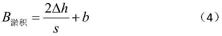
Wherein s is the slope ratio of the side slope of the original channel, and b is the width of the channel bottom of the original channel;
s3-4, obtaining the channel bottom coefficient K according to the actual situation of the channel sectionB;
S3-5, calculating the layered flow Q of each layer1,2,3,...,n-1,nThe formula for n is 1

The calculation formula of n is more than or equal to 2
Flow Q corresponding to the same sedimentation layerSilting upThe corresponding calculation formula is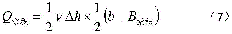
S3-6, the formula for accurately measuring the flow after removing the siltation is Q ═ Q1+Q2+...+Qn-1+Qn-QSilting up+QSurface layer (8)
5. The automated and accurate flow metering method for a silt-laden channel of claim 4, which is characterized in that: for the channel bottom width b less than or equal to 25m, the number of layers is n less than or equal to 4.
Priority Applications (1)
| Application Number | Priority Date | Filing Date | Title |
|---|---|---|---|
| CN202010897854.XA CN112052425B (en) | 2020-08-31 | 2020-08-31 | Automatic and accurate manual multi-sediment open channel flow metering method |
Applications Claiming Priority (1)
| Application Number | Priority Date | Filing Date | Title |
|---|---|---|---|
| CN202010897854.XA CN112052425B (en) | 2020-08-31 | 2020-08-31 | Automatic and accurate manual multi-sediment open channel flow metering method |
Publications (2)
| Publication Number | Publication Date |
|---|---|
| CN112052425A true CN112052425A (en) | 2020-12-08 |
| CN112052425B CN112052425B (en) | 2022-01-14 |
Family
ID=73608312
Family Applications (1)
| Application Number | Title | Priority Date | Filing Date |
|---|---|---|---|
| CN202010897854.XA Expired - Fee Related CN112052425B (en) | 2020-08-31 | 2020-08-31 | Automatic and accurate manual multi-sediment open channel flow metering method |
Country Status (1)
| Country | Link |
|---|---|
| CN (1) | CN112052425B (en) |
Cited By (1)
| Publication number | Priority date | Publication date | Assignee | Title |
|---|---|---|---|---|
| CN113639806A (en) * | 2021-10-19 | 2021-11-12 | 交通运输部天津水运工程科学研究所 | A kind of automatic measuring device and measuring method of irrigation branch canal flow |
Citations (4)
| Publication number | Priority date | Publication date | Assignee | Title |
|---|---|---|---|---|
| US20150125212A1 (en) * | 2013-11-05 | 2015-05-07 | Crystal Lagoons (Curacao) B.V | Floating lake system and methods of treating water within a floating lake |
| CN108225244A (en) * | 2017-12-29 | 2018-06-29 | 深圳市宏电技术股份有限公司 | The measuring method and system of a kind of deposition thickness |
| CN208223565U (en) * | 2018-05-28 | 2018-12-11 | 武汉大学 | A kind of big flow open channel measuring automatically flow system |
| CN110487255A (en) * | 2019-06-25 | 2019-11-22 | 河南黄河河务局信息中心 | A kind of high concentration of sediment canal cross section Scour and Accretion intellectualized detection device |
-
2020
- 2020-08-31 CN CN202010897854.XA patent/CN112052425B/en not_active Expired - Fee Related
Patent Citations (4)
| Publication number | Priority date | Publication date | Assignee | Title |
|---|---|---|---|---|
| US20150125212A1 (en) * | 2013-11-05 | 2015-05-07 | Crystal Lagoons (Curacao) B.V | Floating lake system and methods of treating water within a floating lake |
| CN108225244A (en) * | 2017-12-29 | 2018-06-29 | 深圳市宏电技术股份有限公司 | The measuring method and system of a kind of deposition thickness |
| CN208223565U (en) * | 2018-05-28 | 2018-12-11 | 武汉大学 | A kind of big flow open channel measuring automatically flow system |
| CN110487255A (en) * | 2019-06-25 | 2019-11-22 | 河南黄河河务局信息中心 | A kind of high concentration of sediment canal cross section Scour and Accretion intellectualized detection device |
Cited By (1)
| Publication number | Priority date | Publication date | Assignee | Title |
|---|---|---|---|---|
| CN113639806A (en) * | 2021-10-19 | 2021-11-12 | 交通运输部天津水运工程科学研究所 | A kind of automatic measuring device and measuring method of irrigation branch canal flow |
Also Published As
| Publication number | Publication date |
|---|---|
| CN112052425B (en) | 2022-01-14 |
Similar Documents
| Publication | Publication Date | Title |
|---|---|---|
| CN108254032B (en) | River ultrasonic time difference method flow calculation method | |
| CN113219202B (en) | River hydrological measuring method and device | |
| CN119509815B (en) | Intelligent sensor-based vertical surface measurement system and method for dam gate slot | |
| CN108225244B (en) | Method and system for measuring deposition thickness | |
| CN110847112B (en) | River flood discharge early warning method based on hydraulics simulation | |
| CN112052425B (en) | Automatic and accurate manual multi-sediment open channel flow metering method | |
| CN117291119A (en) | A method for analyzing the grading accumulation characteristics of debris flow particles in channel flash floods | |
| CN107131858A (en) | A kind of method for calculating Lake Bank broken sea dam deposit thickness | |
| CN110955860B (en) | Method for estimating underwater flow shear characteristic parameters of vertical launching navigation body | |
| CN111400974A (en) | A Method for Estimating Shear Stresses of Rectangular Canal Wall and Bed | |
| CN119808662B (en) | Method and system for calculating flow near the riverbed using acoustic time difference method | |
| CN105547638A (en) | Thin layer water flow rolling wave measurement system based on pressure sensor and method thereof | |
| CN108427654A (en) | A kind of medium-sized or above silt arrester has deposited the quick calculation method of storage capacity | |
| CN116519264B (en) | Dynamic determination method and device for comprehensive roughness coefficient of debris flow channel section | |
| CN111985164B (en) | River flow prediction method based on hydrodynamic force and sectional Manning formula | |
| CN105466527A (en) | Thin sheet flow roll wave measurement system and method based on electromagnetic sensors | |
| CN113887033A (en) | Prediction method for sediment accumulation in tidal river section | |
| Robinson | Influence of ice-covers on stream hydraulics and geometric characteristics of alternate bars in rivers: an experimental study | |
| CN114595596A (en) | A simulation method for the compaction and settlement rate of reservoir sediments | |
| CN120948822A (en) | A speed measurement method based on an intelligent flow measurement robot | |
| CN119166956B (en) | A calculation method for flow rate of plane arc double-opening gate | |
| CN116644499B (en) | Determination method suitable for action range of canal wave bank slope impact area and ship traveling wave model test device | |
| CN121482602A (en) | A smart water conservancy monitoring method for sudden rises in river water levels during the flood season | |
| CN111121684B (en) | Measuring structure and calculating method for pipeline siltation | |
| CN120030744A (en) | Intelligent measurement method for water diversion data in open channels prone to siltation based on digital twins |
Legal Events
| Date | Code | Title | Description |
|---|---|---|---|
| PB01 | Publication | ||
| PB01 | Publication | ||
| SE01 | Entry into force of request for substantive examination | ||
| SE01 | Entry into force of request for substantive examination | ||
| GR01 | Patent grant | ||
| GR01 | Patent grant | ||
| CF01 | Termination of patent right due to non-payment of annual fee |
Granted publication date: 20220114 |
|
| CF01 | Termination of patent right due to non-payment of annual fee |