CN112092016A - Multi-source data joint diagnosis method for inspection robot of intelligent substation - Google Patents
Multi-source data joint diagnosis method for inspection robot of intelligent substation Download PDFInfo
- Publication number
- CN112092016A CN112092016A CN202011136804.6A CN202011136804A CN112092016A CN 112092016 A CN112092016 A CN 112092016A CN 202011136804 A CN202011136804 A CN 202011136804A CN 112092016 A CN112092016 A CN 112092016A
- Authority
- CN
- China
- Prior art keywords
- data
- inspection robot
- acquiring
- diagnosis method
- intelligent substation
- Prior art date
- Legal status (The legal status is an assumption and is not a legal conclusion. Google has not performed a legal analysis and makes no representation as to the accuracy of the status listed.)
- Granted
Links
Images


Classifications
-
- B—PERFORMING OPERATIONS; TRANSPORTING
- B25—HAND TOOLS; PORTABLE POWER-DRIVEN TOOLS; MANIPULATORS
- B25J—MANIPULATORS; CHAMBERS PROVIDED WITH MANIPULATION DEVICES
- B25J19/00—Accessories fitted to manipulators, e.g. for monitoring, for viewing; Safety devices combined with or specially adapted for use in connection with manipulators
- B25J19/0095—Means or methods for testing manipulators
-
- B—PERFORMING OPERATIONS; TRANSPORTING
- B25—HAND TOOLS; PORTABLE POWER-DRIVEN TOOLS; MANIPULATORS
- B25J—MANIPULATORS; CHAMBERS PROVIDED WITH MANIPULATION DEVICES
- B25J9/00—Program-controlled manipulators
- B25J9/16—Program controls
-
- G—PHYSICS
- G01—MEASURING; TESTING
- G01D—MEASURING NOT SPECIALLY ADAPTED FOR A SPECIFIC VARIABLE; ARRANGEMENTS FOR MEASURING TWO OR MORE VARIABLES NOT COVERED IN A SINGLE OTHER SUBCLASS; TARIFF METERING APPARATUS; MEASURING OR TESTING NOT OTHERWISE PROVIDED FOR
- G01D21/00—Measuring or testing not otherwise provided for
- G01D21/02—Measuring two or more variables by means not covered by a single other subclass
Landscapes
- Engineering & Computer Science (AREA)
- Robotics (AREA)
- Mechanical Engineering (AREA)
- Physics & Mathematics (AREA)
- General Physics & Mathematics (AREA)
- Manipulator (AREA)
Abstract
A multisource data joint diagnosis method for an intelligent substation inspection robot comprises the following steps: measuring the quantity of instantaneous data passing through a data channel of the inspection robot at each moment; obtaining a mode value of the instantaneous data quantity; acquiring a preset maximum value of the number of data allowed to pass through by the data channel; judging whether the mode value is larger than the preset maximum value or not; if so, taking the mode value as a new preset maximum value of the data quantity allowed to pass through by the data channel; if not, keeping the preset maximum value of the data quantity allowed to pass through by the data channel. The multisource data joint diagnosis method for the inspection robot of the intelligent substation can adjust the number of data allowed to pass through by the data channels in real time according to the number of data passed by each data channel, and reduces the occurrence of data loss caused by undersize of the data channels.
Description
Technical Field
The invention belongs to the technical field of inspection robots, and particularly relates to a multisource data joint diagnosis method for an inspection robot of an intelligent substation.
Background
The inspection robot receives data sent by multiple parties in the inspection process, such as background control data, forward shooting data, navigation data and the like, the data are transmitted in real time, the data volume changes frequently, and sometimes, when the data volume exceeds the maximum receiving volume of a transmission interface, partial data can be lost, and the fault of the inspection robot can be possibly caused.
Disclosure of Invention
In order to solve the problems, the invention provides a multisource data joint diagnosis method for an intelligent substation inspection robot, which comprises the following steps:
measuring the quantity of instantaneous data passing through a data channel of the inspection robot at each moment;
obtaining a mode value of the instantaneous data quantity;
acquiring a preset maximum value of the number of data allowed to pass through by the data channel;
judging whether the mode value is larger than the preset maximum value or not;
if so, taking the mode value as a new preset maximum value of the data quantity allowed to pass through by the data channel;
if not, keeping the preset maximum value of the data quantity allowed to pass through by the data channel.
Preferably, before the step of measuring the instantaneous data quantity passing by the data channel of the inspection robot at each moment, the method further comprises the following steps:
acquiring the data transmission direction of the inspection robot;
distributing a corresponding number of data channels according to the data transmission direction;
and allocating a maximum data quantity value to each data channel.
Preferably, the acquiring the data transmission direction of the inspection robot includes:
sending detection signals with preset frequency to a preset space around the inspection robot in an omnidirectional manner;
acquiring a reflected signal corresponding to the detection signal;
analyzing the corresponding relation between the detection signal and the reflection signal;
and determining the data transmission direction of the inspection robot.
Preferably, the omni-directionally transmitting the detection signal of the preset frequency to the preset space around the inspection robot comprises the following steps:
acquiring the current position coordinate of the inspection robot;
acquiring a data receiving distance of the inspection robot;
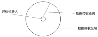
the current position coordinate is used as a circle center, the data receiving distance is used as a radius to form a circle, and a data receiving area of the inspection robot is constructed;
and transmitting detection signals of different frequencies in an omnidirectional mode in the data receiving area.
Preferably, the analyzing the correspondence between the detection signal and the reflection signal includes the steps of:
acquiring a first frequency and a first position of a detection signal sent by the inspection robot;
acquiring a second frequency and a second position of a reflected signal received by the inspection robot;
judging whether the first frequency and the first position are respectively corresponding to the same as the second frequency and the second position;
if so, determining that the detection signal at the first position corresponds to the reflection signal at the second position;
if not, determining that the detection signal at the first position does not correspond to the reflection signal at the second position.
Preferably, the determining the data transmission direction of the inspection robot includes the steps of:
acquiring the direction of the inspection robot relative to the detection signal and the reflected signal;
and determining the direction as the data transmission direction of the inspection robot.
Preferably, the obtaining the mode value of the instantaneous data quantity comprises the steps of:
acquiring the quantity of the instantaneous data passing through the data channel of the inspection robot at each moment;
listing all the instantaneous data quantities according to the time sequence;
finding a mode value of all the instantaneous data quantities according to a list.
Preferably, after said allocating the maximum value of the data quantity to each of said data channels, the method further comprises the steps of:
and allocating a corresponding number of spare data channels to each data channel.
Preferably, after the step of taking the mode value as a new preset maximum value of the data quantity allowed to pass through by the data channel, the method further comprises the following steps:
and calling the standby data channel corresponding to the data channel to allow the data to pass through.
The multisource data joint diagnosis method for the inspection robot of the intelligent substation can adjust the number of data allowed to pass through by the data channels in real time according to the number of data passed by each data channel, and reduces the occurrence of data loss caused by undersize of the data channels.
Drawings
In order to more clearly illustrate the embodiments of the present invention or the technical solutions in the prior art, the drawings used in the description of the embodiments or the prior art will be briefly described below, and it is obvious that the drawings in the following description are only some embodiments of the present invention, and for those skilled in the art, other drawings can be obtained according to these drawings without creative efforts.
FIG. 1 is a flow diagram of a multisource data joint diagnosis method for an intelligent substation inspection robot provided by the invention;
FIG. 2 is a schematic diagram of a multisource data joint diagnosis method for an intelligent substation inspection robot provided by the invention;
fig. 3 is a schematic diagram of a multisource data joint diagnosis method for an intelligent substation inspection robot provided by the invention.
Detailed Description
In order to make the objects, technical solutions and advantages of the present invention more apparent, the present invention will be described in further detail with reference to the accompanying drawings in conjunction with the following detailed description. It should be understood that the description is intended to be exemplary only, and is not intended to limit the scope of the present invention. Moreover, in the following description, descriptions of well-known structures and techniques are omitted so as to not unnecessarily obscure the concepts of the present invention.
As shown in fig. 1, in the embodiment of the present application, the present application provides a multisource data joint diagnosis method for an intelligent substation inspection robot, where the method includes the steps of:
s101: measuring the quantity of instantaneous data passing through a data channel of the inspection robot at each moment;
s102: obtaining a mode value of the instantaneous data quantity;
s103: acquiring a preset maximum value of the number of data allowed to pass through by the data channel;
s104: judging whether the mode value is larger than the preset maximum value or not;
s105: if so, taking the mode value as a new preset maximum value of the data quantity allowed to pass through by the data channel;
s106: if not, keeping the preset maximum value of the data quantity allowed to pass through by the data channel.
As shown in fig. 2, in the embodiment of the present application, before the step S101 of measuring the amount of instantaneous data passing through the data channel of the inspection robot at each moment, the method further includes the steps of:
acquiring the data transmission direction of the inspection robot;
distributing a corresponding number of data channels according to the data transmission direction;
and allocating a maximum data quantity value to each data channel.
In the embodiment of the present application, as shown in fig. 2, the signals a and B are sent to the inspection robot, and at this time, the inspection robot needs to determine the transmission directions of the signals a and B, and then allocate a corresponding number of data channels in the corresponding directions to allow data to pass through.
In this embodiment of the application, obtaining the data transmission direction of the inspection robot includes:
sending detection signals with preset frequency to a preset space around the inspection robot in an omnidirectional manner;
acquiring a reflected signal corresponding to the detection signal;
analyzing the corresponding relation between the detection signal and the reflection signal;
and determining the data transmission direction of the inspection robot.
In the embodiment of the application, the inspection robot firstly transmits an omnidirectional detection signal to the surrounding space and then acquires a reflected signal, if the detection signal and the reflected signal have the same frequency in the same direction, it can be determined that data in the direction can be transmitted, and if only the detection signal but not the reflected signal exists, the data in the direction cannot be transmitted.
As shown in fig. 3, in the embodiment of the present application, the sending a detection signal of a preset frequency to a preset space around the inspection robot in an omnidirectional manner includes:
acquiring the current position coordinate of the inspection robot;
acquiring a data receiving distance of the inspection robot;
the current position coordinate is used as a circle center, the data receiving distance is used as a radius to form a circle, and a data receiving area of the inspection robot is constructed;
and transmitting detection signals of different frequencies in an omnidirectional mode in the data receiving area.
In the embodiment of the present application, as shown in fig. 3, a data receiving area is constructed in the spherical space around the inspection robot through the above-mentioned operations, and then the inspection robot transmits the detection signals of different frequencies in all directions in the data receiving area.
In an embodiment of the present application, the analyzing the correspondence between the detection signal and the reflection signal includes:
acquiring a first frequency and a first position of a detection signal sent by the inspection robot;
acquiring a second frequency and a second position of a reflected signal received by the inspection robot;
judging whether the first frequency and the first position are respectively corresponding to the same as the second frequency and the second position;
if so, determining that the detection signal at the first position corresponds to the reflection signal at the second position;
if not, determining that the detection signal at the first position does not correspond to the reflection signal at the second position.
In the embodiment of the application, whether the detection signal and the transmission signal correspond to each other is judged by judging the frequency and the position of the detection signal and the transmission signal. When the two are the same, the two are considered to be corresponding; when either one of the two is different, the two are not corresponding.
In an embodiment of the present application, the determining the data transmission direction of the inspection robot includes:
acquiring the direction of the inspection robot relative to the detection signal and the reflected signal;
and determining the direction as the data transmission direction of the inspection robot.
In the embodiment of the application, when the detection signal corresponds to the reflection signal, the directions of the detection signal and the reflection signal can be regarded as the data transmission direction of the inspection robot.
In an embodiment of the present application, the obtaining a mode value of the instantaneous data quantity includes:
acquiring the quantity of the instantaneous data passing through the data channel of the inspection robot at each moment;
listing all the instantaneous data quantities according to the time sequence;
finding a mode value of all the instantaneous data quantities according to a list.
In the embodiment of the present application, all the homeopathic data quantities may be tabulated, and a mode value of the instantaneous data quantity is obtained through analysis of the tabulated data.
Preferably, after said allocating the maximum value of the data quantity to each of said data channels, the method further comprises the steps of:
and allocating a corresponding number of spare data channels to each data channel.
In this embodiment of the present application, after the taking the mode value as a new preset maximum value of the amount of data allowed to pass through by the data channel, the method further includes:
and calling the standby data channel corresponding to the data channel to allow the data to pass through.
In the embodiment of the present application, when a new data passing data amount is set for one data channel, it indicates that the data amount in the data channel is large, and at this time, a corresponding standby data channel may be called to allow data to pass.
The multisource data joint diagnosis method for the inspection robot of the intelligent substation can adjust the number of data allowed to pass through by the data channels in real time according to the number of data passed by each data channel, and reduces the occurrence of data loss caused by undersize of the data channels.
It is to be understood that the above-described embodiments of the present invention are merely illustrative of or explaining the principles of the invention and are not to be construed as limiting the invention. Therefore, any modification, equivalent replacement, improvement and the like made without departing from the spirit and scope of the present invention should be included in the protection scope of the present invention. Further, it is intended that the appended claims cover all such variations and modifications as fall within the scope and boundaries of the appended claims or the equivalents of such scope and boundaries.
Claims (9)
1. A multisource data joint diagnosis method for an intelligent substation inspection robot is characterized by comprising the following steps:
measuring the quantity of instantaneous data passing through a data channel of the inspection robot at each moment;
obtaining a mode value of the instantaneous data quantity;
acquiring a preset maximum value of the number of data allowed to pass through by the data channel;
judging whether the mode value is larger than the preset maximum value or not;
if so, taking the mode value as a new preset maximum value of the data quantity allowed to pass through by the data channel;
if not, keeping the preset maximum value of the data quantity allowed to pass through by the data channel.
2. The intelligent substation inspection robot multi-source data joint diagnosis method according to claim 1, characterized by further comprising the steps of, before measuring the amount of instantaneous data passing through an inspection robot data channel at each moment:
acquiring the data transmission direction of the inspection robot;
distributing a corresponding number of data channels according to the data transmission direction;
and allocating a maximum data quantity value to each data channel.
3. The multi-source data joint diagnosis method for the inspection robot of the intelligent substation according to claim 2, wherein the step of obtaining the data transmission direction of the inspection robot comprises the following steps:
sending detection signals with preset frequency to a preset space around the inspection robot in an omnidirectional manner;
acquiring a reflected signal corresponding to the detection signal;
analyzing the corresponding relation between the detection signal and the reflection signal;
and determining the data transmission direction of the inspection robot.
4. The multi-source data joint diagnosis method for the inspection robot of the intelligent substation according to claim 3, wherein the omni-directional transmission of the detection signal with the preset frequency to the preset space around the inspection robot comprises the following steps:
acquiring the current position coordinate of the inspection robot;
acquiring a data receiving distance of the inspection robot;
the current position coordinate is used as a circle center, the data receiving distance is used as a radius to form a circle, and a data receiving area of the inspection robot is constructed;
and transmitting detection signals of different frequencies in an omnidirectional mode in the data receiving area.
5. The intelligent substation inspection robot multi-source data joint diagnosis method according to claim 3, wherein the analyzing the corresponding relationship between the detection signal and the reflection signal comprises the steps of:
acquiring a first frequency and a first position of a detection signal sent by the inspection robot;
acquiring a second frequency and a second position of a reflected signal received by the inspection robot;
judging whether the first frequency and the first position are respectively corresponding to the same as the second frequency and the second position;
if so, determining that the detection signal at the first position corresponds to the reflection signal at the second position;
if not, determining that the detection signal at the first position does not correspond to the reflection signal at the second position.
6. The multi-source data joint diagnosis method for the inspection robot of the intelligent substation according to claim 3, wherein the step of determining the data transmission direction of the inspection robot comprises the following steps:
acquiring the direction of the inspection robot relative to the detection signal and the reflected signal;
and determining the direction as the data transmission direction of the inspection robot.
7. The intelligent substation inspection robot multi-source data joint diagnosis method according to claim 1, wherein the obtaining of the mode value of the instantaneous data quantity comprises:
acquiring the quantity of the instantaneous data passing through the data channel of the inspection robot at each moment;
listing all the instantaneous data quantities according to the time sequence;
finding a mode value of all the instantaneous data quantities according to a list.
8. The intelligent substation inspection robot multi-source data joint diagnosis method according to claim 2, further comprising the following steps after the maximum data quantity is allocated to each data channel:
and allocating a corresponding number of spare data channels to each data channel.
9. The intelligent substation inspection robot multi-source data joint diagnosis method according to claim 1, further comprising, after taking the mode value as a new preset maximum value of the data quantity allowed to pass through by the data channel, the steps of:
and calling the standby data channel corresponding to the data channel to allow the data to pass through.
Applications Claiming Priority (2)
| Application Number | Priority Date | Filing Date | Title |
|---|---|---|---|
| CN2020106653789 | 2020-07-11 | ||
| CN202010665378 | 2020-07-11 |
Publications (2)
| Publication Number | Publication Date |
|---|---|
| CN112092016A true CN112092016A (en) | 2020-12-18 |
| CN112092016B CN112092016B (en) | 2024-06-07 |
Family
ID=73785971
Family Applications (1)
| Application Number | Title | Priority Date | Filing Date |
|---|---|---|---|
| CN202011136804.6A Active CN112092016B (en) | 2020-07-11 | 2020-10-22 | Multi-source data joint diagnosis method for intelligent substation inspection robot |
Country Status (1)
| Country | Link |
|---|---|
| CN (1) | CN112092016B (en) |
Cited By (1)
| Publication number | Priority date | Publication date | Assignee | Title |
|---|---|---|---|---|
| CN119884555A (en) * | 2025-03-26 | 2025-04-25 | 西安康创电子科技有限公司 | Data analysis method and system of aviation accessory measurement device system |
Citations (12)
| Publication number | Priority date | Publication date | Assignee | Title |
|---|---|---|---|---|
| US6429804B1 (en) * | 1999-11-24 | 2002-08-06 | Fujitsu Ten Limited | Motor-vehicle-mounted radar apparatus |
| US20030007456A1 (en) * | 2001-06-25 | 2003-01-09 | Praveen Gupta | Triggered packet data rate change in a communication system |
| CN102116625A (en) * | 2009-12-31 | 2011-07-06 | 武汉大学 | GIS (geographic information system)-GPS (global position system) navigation method of inspection robot |
| CN105922287A (en) * | 2016-05-27 | 2016-09-07 | 中国电力科学研究院 | Movement function experimental method of substation intelligent patrol robots |
| CN107255712A (en) * | 2017-05-03 | 2017-10-17 | 上海交通大学 | A kind of immunochromatography chip quantified system analysis based on smart mobile phone |
| CN206733013U (en) * | 2017-04-12 | 2017-12-12 | 国网山东省电力公司电力科学研究院 | A kind of Intelligent Mobile Robot for possessing redundant communication paths |
| WO2018032933A1 (en) * | 2016-08-17 | 2018-02-22 | 国网山东省电力公司电力科学研究院 | Substation inspection robot navigation control system and method |
| CN109600315A (en) * | 2017-09-30 | 2019-04-09 | 阿里巴巴集团控股有限公司 | The flow control method and method of adjustment of data channel |
| CN110514957A (en) * | 2019-08-19 | 2019-11-29 | 深圳供电局有限公司 | Automatic inspection method and platform for transformer substation |
| CN110687925A (en) * | 2019-11-12 | 2020-01-14 | 贵州电网有限责任公司 | Unmanned aerial vehicle autonomous cruise wire and ground wire inspection detection device and method |
| WO2020019512A1 (en) * | 2018-07-26 | 2020-01-30 | 平安科技(深圳)有限公司 | Robot positioning detection method and apparatus and computer readable storage medium |
| CN110887455A (en) * | 2019-11-20 | 2020-03-17 | 山东农业大学 | A method for eliminating jitter error of electronic tree altimeter based on mode |
-
2020
- 2020-10-22 CN CN202011136804.6A patent/CN112092016B/en active Active
Patent Citations (12)
| Publication number | Priority date | Publication date | Assignee | Title |
|---|---|---|---|---|
| US6429804B1 (en) * | 1999-11-24 | 2002-08-06 | Fujitsu Ten Limited | Motor-vehicle-mounted radar apparatus |
| US20030007456A1 (en) * | 2001-06-25 | 2003-01-09 | Praveen Gupta | Triggered packet data rate change in a communication system |
| CN102116625A (en) * | 2009-12-31 | 2011-07-06 | 武汉大学 | GIS (geographic information system)-GPS (global position system) navigation method of inspection robot |
| CN105922287A (en) * | 2016-05-27 | 2016-09-07 | 中国电力科学研究院 | Movement function experimental method of substation intelligent patrol robots |
| WO2018032933A1 (en) * | 2016-08-17 | 2018-02-22 | 国网山东省电力公司电力科学研究院 | Substation inspection robot navigation control system and method |
| CN206733013U (en) * | 2017-04-12 | 2017-12-12 | 国网山东省电力公司电力科学研究院 | A kind of Intelligent Mobile Robot for possessing redundant communication paths |
| CN107255712A (en) * | 2017-05-03 | 2017-10-17 | 上海交通大学 | A kind of immunochromatography chip quantified system analysis based on smart mobile phone |
| CN109600315A (en) * | 2017-09-30 | 2019-04-09 | 阿里巴巴集团控股有限公司 | The flow control method and method of adjustment of data channel |
| WO2020019512A1 (en) * | 2018-07-26 | 2020-01-30 | 平安科技(深圳)有限公司 | Robot positioning detection method and apparatus and computer readable storage medium |
| CN110514957A (en) * | 2019-08-19 | 2019-11-29 | 深圳供电局有限公司 | Automatic inspection method and platform for transformer substation |
| CN110687925A (en) * | 2019-11-12 | 2020-01-14 | 贵州电网有限责任公司 | Unmanned aerial vehicle autonomous cruise wire and ground wire inspection detection device and method |
| CN110887455A (en) * | 2019-11-20 | 2020-03-17 | 山东农业大学 | A method for eliminating jitter error of electronic tree altimeter based on mode |
Non-Patent Citations (1)
| Title |
|---|
| 贤家洁;林阳坡;赖斌;陈如洲;: "基于激光导航路径识别的电力巡检智能机器人设计", 中国新技术新产品, no. 23, 10 December 2016 (2016-12-10), pages 11 - 12 * |
Cited By (2)
| Publication number | Priority date | Publication date | Assignee | Title |
|---|---|---|---|---|
| CN119884555A (en) * | 2025-03-26 | 2025-04-25 | 西安康创电子科技有限公司 | Data analysis method and system of aviation accessory measurement device system |
| CN119884555B (en) * | 2025-03-26 | 2025-05-30 | 西安康创电子科技有限公司 | Data analysis method and system of aviation accessory measurement device system |
Also Published As
| Publication number | Publication date |
|---|---|
| CN112092016B (en) | 2024-06-07 |
Similar Documents
| Publication | Publication Date | Title |
|---|---|---|
| Pesko et al. | Radio environment maps: The survey of construction methods. | |
| CN115550358B (en) | Wireless communication transmission method, device and computer equipment for realizing communication perception calculation depth fusion | |
| CN111356142B (en) | Service processing method and device | |
| US8340663B2 (en) | Method and system for ground station signal handover for aircraft | |
| EP4188033A1 (en) | Method and device for link switching during sidelink communication | |
| CN114449437A (en) | Interference processing method, device and equipment and readable storage medium | |
| EP3297345B1 (en) | Wireless local area network based positioning method and device | |
| WO2020243971A8 (en) | Resource selection method in internet of vehicles system and user equipment thereof | |
| CN113179541B (en) | Unmanned aerial vehicle communication method and device based on microwave image transmission and cellular network | |
| WO2021227715A1 (en) | Method for measuring candidate beam, and terminal, network device, chip system and medium | |
| CN112092016B (en) | Multi-source data joint diagnosis method for intelligent substation inspection robot | |
| CN105637927A (en) | Communication access method and user equipment | |
| CN119095176A (en) | A method and device for integrating synaesthesia | |
| WO2024105646A1 (en) | Unmanned aerial vehicle detection and localization with cellular network infrastructure augmented by reconfigurable intelligent surfaces | |
| KR102649097B1 (en) | Method and apparatus for performing drive test in a mobile communication system | |
| CN113329470A (en) | Network resource allocation method and device, terminal equipment and target base station | |
| CN115665891B (en) | A Decentralized Distributed Radar System | |
| CN120419217A (en) | Configuration method, device, equipment and storage medium based on perception scene | |
| CN115379476B (en) | Methods, devices, equipment and storage media for determining cell interference types | |
| EP2144461A2 (en) | Insensitive area detecting method and apparatus for the same in radio communication system | |
| CN115549756B (en) | An anti-interference implementation method for automatic switching of satellite-ground collaborative measurement and control links | |
| CN115379477B (en) | Method, device, equipment and storage medium for determining cell interference type | |
| CN119815269A (en) | Communication perception method, communication perception integrated network element, perception network element and system | |
| CN210899631U (en) | VSAT antenna remote control system based on big dipper short message | |
| CN114371450A (en) | Radar anti-interference identification method and device and computer equipment |
Legal Events
| Date | Code | Title | Description |
|---|---|---|---|
| PB01 | Publication | ||
| PB01 | Publication | ||
| SE01 | Entry into force of request for substantive examination | ||
| SE01 | Entry into force of request for substantive examination | ||
| GR01 | Patent grant |