CN112123733A - Double-layer hollow tube mold - Google Patents
Double-layer hollow tube mold Download PDFInfo
- Publication number
- CN112123733A CN112123733A CN202010704496.6A CN202010704496A CN112123733A CN 112123733 A CN112123733 A CN 112123733A CN 202010704496 A CN202010704496 A CN 202010704496A CN 112123733 A CN112123733 A CN 112123733A
- Authority
- CN
- China
- Prior art keywords
- mold
- core
- inlet
- sleeved
- core mold
- Prior art date
- Legal status (The legal status is an assumption and is not a legal conclusion. Google has not performed a legal analysis and makes no representation as to the accuracy of the status listed.)
- Pending
Links
Images


Classifications
-
- B—PERFORMING OPERATIONS; TRANSPORTING
- B29—WORKING OF PLASTICS; WORKING OF SUBSTANCES IN A PLASTIC STATE IN GENERAL
- B29C—SHAPING OR JOINING OF PLASTICS; SHAPING OF MATERIAL IN A PLASTIC STATE, NOT OTHERWISE PROVIDED FOR; AFTER-TREATMENT OF THE SHAPED PRODUCTS, e.g. REPAIRING
- B29C48/00—Extrusion moulding, i.e. expressing the moulding material through a die or nozzle which imparts the desired form; Apparatus therefor
- B29C48/25—Component parts, details or accessories; Auxiliary operations
- B29C48/30—Extrusion nozzles or dies
- B29C48/32—Extrusion nozzles or dies with annular openings, e.g. for forming tubular articles
- B29C48/335—Multiple annular extrusion nozzles in coaxial arrangement, e.g. for making multi-layered tubular articles
-
- B—PERFORMING OPERATIONS; TRANSPORTING
- B29—WORKING OF PLASTICS; WORKING OF SUBSTANCES IN A PLASTIC STATE IN GENERAL
- B29C—SHAPING OR JOINING OF PLASTICS; SHAPING OF MATERIAL IN A PLASTIC STATE, NOT OTHERWISE PROVIDED FOR; AFTER-TREATMENT OF THE SHAPED PRODUCTS, e.g. REPAIRING
- B29C48/00—Extrusion moulding, i.e. expressing the moulding material through a die or nozzle which imparts the desired form; Apparatus therefor
- B29C48/03—Extrusion moulding, i.e. expressing the moulding material through a die or nozzle which imparts the desired form; Apparatus therefor characterised by the shape of the extruded material at extrusion
- B29C48/09—Articles with cross-sections having partially or fully enclosed cavities, e.g. pipes or channels
-
- B—PERFORMING OPERATIONS; TRANSPORTING
- B29—WORKING OF PLASTICS; WORKING OF SUBSTANCES IN A PLASTIC STATE IN GENERAL
- B29L—INDEXING SCHEME ASSOCIATED WITH SUBCLASS B29C, RELATING TO PARTICULAR ARTICLES
- B29L2023/00—Tubular articles
- B29L2023/22—Tubes or pipes, i.e. rigid
Landscapes
- Engineering & Computer Science (AREA)
- Mechanical Engineering (AREA)
- Manufacturing & Machinery (AREA)
- Extrusion Moulding Of Plastics Or The Like (AREA)
Abstract
本发明提供一种双层中空管模具,包括入口模,所述入口模一端固定连接分流装置,所述分流装置背离入口模的一面安装有第一芯模,所述第一芯模上套设有第一中模,所述第一中模上套设有用于压持第一中模的第一外模,所述第一芯模远离分流装置的一端安装有第二芯模,所述第二芯模上套设有与第一中模相配合的第二中模,所述第二中模上套设有用于压持第二中模的第二外模,与现有技术相比,本发明具有如下的有益效果:实现便捷加工双材质的双层中空管。
The invention provides a double-layer hollow tube mold, which includes an inlet mold, one end of the inlet mold is fixedly connected to a shunt device, and a first core mold is installed on the side of the flow shunt device facing away from the inlet mold, and the first core mold is sleeved A first middle mold is provided, and a first outer mold for pressing and holding the first middle mold is sleeved on the first middle mold. The second core mold is sleeved with a second middle mold matched with the first middle mold, and the second middle mold is sleeved with a second outer mold for pressing and holding the second middle mold. Compared with the prior art , the present invention has the following beneficial effects: realizes convenient processing of double-layer hollow tubes with two materials.
Description
技术领域technical field
本发明是一种双层中空管模具,属于高分子材料挤出技术领域。The invention relates to a double-layer hollow tube mould, which belongs to the technical field of extrusion of polymer materials.
背景技术Background technique
目前,一些高分子材料管道如塑料管由于其卫生、重量轻、阻力小、连接可靠等优点应用广泛,双层中空管道由内管、外管及连接内外管的支撑筋组成,相比实壁管道,其在隔冷隔热、降低噪音方面有明显优势,且可以防止在内管由于结冰、压力过大等因素破裂时介质泄露出整个管道,还可通过检测外管内压力判断内管泄露。而内外层材质不同的双层中空管道,则可以针对上述中空管内外使用情况分别进行优化,如内层耐热卫生、外层抗紫外线抗外界腐蚀老化等特点,目前,现有技术中缺少生产加工内外层材质不同的双层中空管的模具。At present, some polymer material pipes such as plastic pipes are widely used due to their advantages of hygiene, light weight, low resistance and reliable connection. The pipeline has obvious advantages in cold insulation and noise reduction, and can prevent the medium from leaking out of the entire pipeline when the inner pipe is ruptured due to icing, excessive pressure and other factors, and can also judge the leakage of the inner pipe by detecting the inner pressure of the outer pipe . The double-layer hollow pipes with different inner and outer layer materials can be optimized according to the internal and external use conditions of the above-mentioned hollow pipes, such as the inner layer heat-resistant and hygienic, and the outer layer anti-ultraviolet and anti-corrosion and aging characteristics. Production and processing of molds for double-layer hollow tubes with different inner and outer layers.
发明内容SUMMARY OF THE INVENTION
针对现有技术存在的空白,本发明目的是提供一种双层中空管模具,以解决上述背景技术中提出的问题。In view of the gaps in the prior art, the purpose of the present invention is to provide a double-layer hollow tube mold to solve the above-mentioned problems in the background art.
为了实现上述目的,本发明是通过如下的技术方案来实现:一种双层中空管模具,包括入口模,所述入口模一端固定连接分流装置,所述分流装置背离入口模的一面安装有第一芯模,所述第一芯模上套设有第一中模,所述第一中模上套设有用于压持第一中模的第一外模,所述第一外模设置在分流装置内,所述第一外模上套设有用于压持第一外模的第一压紧板,所述第一压紧板通过连接螺丝与分流装置的分流外模固定连接,所述分流装置远离入口模的一端外表面呈环形等距开设有若干个第一螺纹孔,若干个所述第一螺纹孔内均啮合有第一调节螺栓,所述第一芯模远离分流装置的一端安装有第二芯模,所述第二芯模上套设有与第一中模相配合的第二中模,所述第二中模上套设有用于压持第二中模的第二外模,所述第二外模设置在第一压紧板内,所述第二外模上套设有用于压持第二外模位置的第二压紧板,所述第二压紧板通过连接螺丝与第一压紧板固定连接,所述第一压紧板远离分流装置的一端外表面呈环形等距开设有若干个第二螺纹孔,若干个所述第二螺纹孔内均啮合有第二调节螺栓。In order to achieve the above object, the present invention is achieved through the following technical solutions: a double-layer hollow tube mold, including an inlet mold, one end of the inlet mold is fixedly connected to a shunt device, and the side of the shunt device away from the inlet mold is installed with A first core mold, a first middle mold is sleeved on the first core mold, a first outer mold for pressing and holding the first middle mold is sleeved on the first middle mold, and the first outer mold is set In the shunt device, the first outer mold is sleeved with a first pressing plate for pressing and holding the first outer mold. The outer surface of one end of the shunt device away from the inlet die is provided with a plurality of first threaded holes in a ring shape at an equal distance, and a first adjustment bolt is engaged in each of the first threaded holes, and the first core mold is far away from the shunt device. A second core mold is installed on one end, the second core mold is sleeved with a second middle mold matched with the first middle mold, and the second middle mold is sleeved with a first middle mold for pressing and holding the second middle mold. Two outer molds, the second outer mold is set in the first pressing plate, the second outer mold is sleeved with a second pressing plate for pressing the position of the second outer mold, the second pressing plate is The plate is fixedly connected to the first pressing plate through connecting screws, and the outer surface of one end of the first pressing plate away from the shunt device is provided with a plurality of second threaded holes in a ring shape at an equal distance, and the inner surfaces of the plurality of the second threaded holes are equidistant. A second adjustment bolt is engaged.
进一步地,所述分流装置包括分流模,所述分流模通过螺丝与入口模固定连接,所述分流模背离入口模的一面固定连接分流外模,所述分流外模内设有分流中模,所述分流中模内设有分流芯模。Further, the shunt device includes a shunt die, the shunt die is fixedly connected to the inlet die through screws, the side of the shunt die facing away from the inlet die is fixedly connected to the shunt outer die, and the shunt outer die is provided with a shunt middle die, A split core mold is arranged in the split middle mold.
进一步地,所述分流芯模面向第一芯模的一面加工有第三螺纹孔,所述第一芯模面向分流芯模的一面固定有与第三螺纹孔相配合的螺纹柱,所述螺纹柱啮合在第三螺纹孔内。Further, a third threaded hole is machined on the side of the split core mold facing the first core mold, and a threaded column matched with the third threaded hole is fixed on the side of the first core mold facing the split core mold. The post is engaged in the third threaded hole.
进一步地,所述分流芯模面向第一芯模的一面加工有第三螺纹孔,所述第一芯模面向分流芯模的一面开设有与第三螺纹孔相配合的第一通孔,所述第二芯模面向第一芯模的一面开设有与第一通孔相配合的第二通孔,所述第二通孔内设有连接螺丝,所述连接螺丝穿过第一通孔啮合在第三螺纹孔内。Further, a third threaded hole is processed on the side of the split core mold facing the first core mold, and a first through hole matched with the third threaded hole is opened on the side of the first core mold facing the split core mold, so the The side of the second core mold facing the first core mold is provided with a second through hole matched with the first through hole, a connecting screw is arranged in the second through hole, and the connecting screw is engaged through the first through hole in the third threaded hole.
本发明的有益效果:1、可实现不同规格、内外层异种材质的中空管连续生产;可实现内外层壁厚均匀度在线生产时可调;可实现支撑筋的材质与内层或外层一致;可根据需要选择支撑筋数量;可满足不同的管材截面形状。The beneficial effects of the present invention are as follows: 1. It can realize the continuous production of hollow tubes with different specifications and different materials for the inner and outer layers; it can realize that the wall thickness uniformity of the inner and outer layers can be adjusted during online production; Consistent; the number of support ribs can be selected according to needs; it can meet different pipe cross-sectional shapes.
2、支撑筋的空腔填充是在调整规格时同时完成,保证了制品的致密性,防止气泡产生。2. The cavity filling of the support ribs is completed at the same time when the specifications are adjusted, which ensures the compactness of the product and prevents the generation of air bubbles.
3、同一截面形状下,更换管规格只需要更换末端的第二中模、第二芯模、第二外模,其余保持不变,方便快捷。3. Under the same cross-sectional shape, only the second middle mold, the second core mold, and the second outer mold at the end need to be replaced to replace the tube specifications, and the rest remain unchanged, which is convenient and quick.
4、流道平滑顺畅,结合合适的入口模和分流装置,可适应多种高分子材料的挤出。4. The flow channel is smooth and smooth, and combined with the appropriate inlet die and shunt device, it can be adapted to the extrusion of various polymer materials.
5、实现了支撑筋贯穿整个管材壁厚,以便提供筋上打孔、内外导电、管对接时支撑筋位置标识等功能。5. Realize that the support rib runs through the entire wall thickness of the pipe, so as to provide functions such as punching on the rib, internal and external conduction, and position identification of the support rib when the pipes are connected.
附图说明Description of drawings
通过阅读参照以下附图对非限制性实施例所作的详细描述,本发明的其它特征、目的和优点将会变得更明显:Other features, objects and advantages of the present invention will become more apparent by reading the detailed description of non-limiting embodiments with reference to the following drawings:
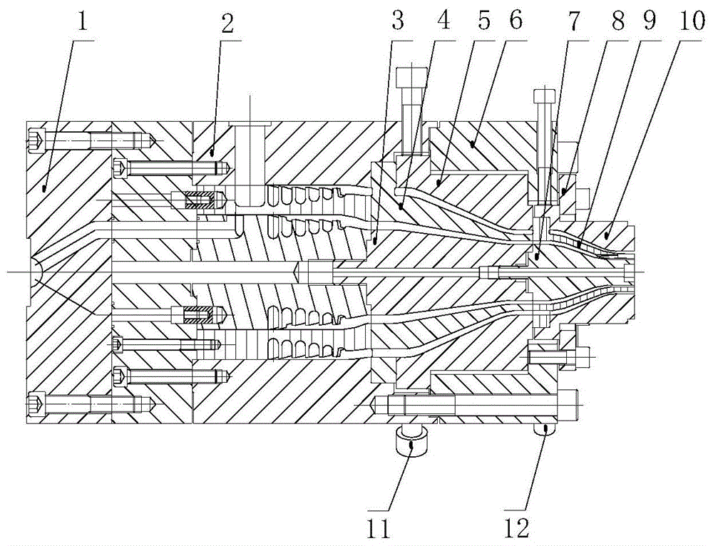
图1为本发明的实施例1的结构示意图;1 is a schematic structural diagram of
图2为本发明一种双层中空管模具中第二中模的立体图;Fig. 2 is the perspective view of the second middle mold in a kind of double-layer hollow tube mold of the present invention;
图3为由图2中第二中模形成的双层中空管的横截面图;Fig. 3 is a cross-sectional view of the double-layer hollow tube formed by the second middle mold in Fig. 2;
图4为本发明的实施例3的结构示意图;4 is a schematic structural diagram of
图5为图4中第二中模的立体图;Fig. 5 is the perspective view of the second middle mold in Fig. 4;
图6为由图5中第二中模形成的双层中空管的横截面图;FIG. 6 is a cross-sectional view of the double-layer hollow tube formed by the second middle mold in FIG. 5;
图7为本发明的实施例4的结构示意图;7 is a schematic structural diagram of
图8为图7中第二中模的立体图;Fig. 8 is the perspective view of the second middle die in Fig. 7;
图9为由图8中第二中模形成的双层中空管的横截面图;FIG. 9 is a cross-sectional view of the double-layer hollow tube formed by the second middle mold in FIG. 8;
图10为本发明的实施例5的结构示意图;10 is a schematic structural diagram of
图11为图10中第二中模的立体图;Figure 11 is a perspective view of the second middle die in Figure 10;
图12为由图11中第二中模形成的双层中空管的横截面图;Figure 12 is a cross-sectional view of the double-layer hollow tube formed by the second middle die in Figure 11;
图中:1-入口模、2-分流装置、3-第一芯模、4-第一中模、5-第一外模、6-第一压紧板、7-第二芯模、8-第二压紧板、9-第二中模、10-第二外模、11-第一调节螺栓、12-第二调节螺栓。In the figure: 1-inlet die, 2-splitting device, 3-first core die, 4-first middle die, 5-first outer die, 6-first compression plate, 7-second core die, 8 -Second pressing plate, 9-Second middle die, 10-Second outer die, 11-First adjusting bolt, 12-Second adjusting bolt.
具体实施方式Detailed ways
为使本发明实现的技术手段、创作特征、达成目的与功效易于明白了解,下面结合具体实施方式,进一步阐述本发明。In order to make the technical means, creative features, achievement goals and effects realized by the present invention easy to understand, the present invention will be further described below with reference to the specific embodiments.
实施例1:请参阅图1至图3,本发明提供一种技术方案:一种双层中空管模具,包括入口模1,入口模1一端固定连接分流装置2,将两股熔体从入口模1入口进入后,分别经分流装置2的通道形成内外层两个均匀流动的圆环形料流,分流装置2流道结构可以是支架式、篮式、螺旋形或其交叉组合,因此入口模1和分流装置2可以是同一个模体,也可以分别是单个、多个模体组成。Embodiment 1: Please refer to FIG. 1 to FIG. 3, the present invention provides a technical solution: a double-layer hollow tube mold, including an
分流装置2背离入口模1的一面安装有第一芯模3,第一芯模3上套设有第一中模4,第一中模4上套设有用于压持第一中模4的第一外模5,第一外模5设置在分流装置2内,经分流装置2的通道形成内外层两个均匀流动的圆环形料流,外层熔体绕过第一中模4流经第一中模4与第一外模5之间的流道并调整尺寸规格,内层熔体流经第一中模4与第一芯模3之间的流道并调整尺寸规格,接着内层、外层一同被挤入第二外模10、第二中模9和第二芯模7组成的结构中。A
第一外模5上套设有用于压持第一外模5的第一压紧板6,第一压紧板6通过连接螺丝与分流装置2的分流外模固定连接,第一压紧板6起到压紧第一外模5的作用。The first
分流装置2远离入口模的一端外表面呈环形等距开设有若干个第一螺纹孔,若干个第一螺纹孔内均啮合有第一调节螺栓11,当挤出的双层中空管的外管壁厚存在厚薄不同的情况时,利用若干个第一螺纹孔内的第一调节螺栓11调整第一外模5的位置,从而使双层中空管的外管壁厚均匀。The outer surface of one end of the
第一芯模3远离分流装置2的一端安装有第二芯模7,第二芯模7上套设有与第一中模4相配合的第二中模9,第二中模9上套设有用于压持第二中模9的第二外模10,第二外模10设置在第一压紧板6内,流入第二外模10、第二中模9和第二芯模7组成结构中的外层熔体流经第二中模9与第二外模10之间的流道并调整尺寸规格,内层熔体流经第二中模9与第二芯模7之间的流道并调整尺寸规格,支撑筋形状包括与内层或外层的界面采用强制分配形成,内层或外层熔体在流经第二中模9时填充第二中模9预留的空腔并与外层或内层熔体复合成形,接着内层、外层和支撑筋一同被挤出模具。One end of the
第二外模10上套设有用于压持第二外模10位置的第二压紧板8,第二压紧板8通过连接螺丝与第一压紧板6固定连接,第二压紧板8起到压紧第二外模10的作用。The second
第一压紧板6远离分流装置2的一端外表面呈环形等距开设有若干个第二螺纹孔,若干个第二螺纹孔内均啮合有第二调节螺栓12,当挤出的双层中空管的内管壁厚存在厚薄不同的情况时,利用若干个第二螺纹孔内的第二调节螺栓12调整第二外模10的位置,从而使双层中空管的外管壁厚均匀,管材截面形状可通过改变第二芯模7、第二中模9和第二外模10流道形状调整,第二中模9作为成形核心部件,其空腔可决定支撑筋数量、材质及形状,当支撑筋材质与内管一致时,作为优选,第一中模4固定不调,第一外模5可调,对应外管壁厚;第二中模9与第二外模10相对固定,一起可调,对应内管壁厚;当支撑筋材质与外管一致时,作为优选,第一外模5固定不调,第一中模4可调,对应内管壁厚;第二中模9与第二芯模7固定不调,第二外模10可调,对应外管壁厚,为实现两层管壁厚相对独立调整,第一压紧板6紧固在分流装置2末端的外层模体,不受第一外模5调整的影响。The outer surface of one end of the first
分流装置2包括分流模,分流模通过螺丝与入口模1固定连接,分流模背离入口模1的一面固定连接分流外模,分流外模内设有分流中模,分流中模内设有分流芯模,入口模1进入到分流模内的熔体一部分流入分流外模与分流中模之间的的流道,另一部分熔体流入分流中模与分流芯模之间的流道,从而形成内外层两个均匀流动的圆环形料流。The
分流芯模面向第一芯模3的一面加工有第三螺纹孔,第一芯模3面向分流芯模的一面固定有与第三螺纹孔相配合的螺纹柱,螺纹柱啮合在第三螺纹孔内,将第一芯模3上的螺纹柱拧入分流芯模上的第三螺纹孔内,实现第一芯模3与分流芯模的固定连接。The side of the split core mold facing the
实施例2:分流芯模面向第一芯模3的一面加工有第三螺纹孔,第一芯模3面向分流芯模的一面开设有与第三螺纹孔相配合的第一通孔,第二芯模7面向第一芯模3的一面开设有与第一通孔相配合的第二通孔,第二通孔内设有连接螺丝,连接螺丝穿过第一通孔啮合在第三螺纹孔内,将连接螺丝穿过第二通孔、第一通孔拧入分流芯模上的第三螺纹孔内,实现第二芯模7、第一芯模3和分流芯模的固定连接。Example 2: The side of the split core mold facing the
实施例3:请参阅图4至图6,采用由附图5所示的第二芯模7,可加工支撑筋与内管为同一材质的双层中空管,并使支撑筋贯穿外管。Example 3: Please refer to FIGS. 4 to 6 , using the
实施例4:请参阅图7至图9,采用由附图8所示的第二芯模7,可加工支撑筋与外管为同一材质的双层中空管,并使支撑筋贯穿内管。Embodiment 4: Please refer to Fig. 7 to Fig. 9. Using the
实施例5:请参阅图10至图12,采用由附图11所示的第二芯模7,可加工支撑筋与外管为同一材质的双层中空管,并使支撑筋贴合在内管表面。Example 5: Please refer to Fig. 10 to Fig. 12. Using the
以上显示和描述了本发明的基本原理和主要特征和本发明的优点,对于本领域技术人员而言,显然本发明不限于上述示范性实施例的细节,而且在不背离本发明的精神或基本特征的情况下,能够以其他的具体形式实现本发明。因此,无论从哪一点来看,均应将实施例看作是示范性的,而且是非限制性的,本发明的范围由所附权利要求而不是上述说明限定,因此旨在将落在权利要求的等同要件的含义和范围内的所有变化囊括在本发明内。The basic principles and main features of the present invention and the advantages of the present invention have been shown and described above, and it will be apparent to those skilled in the art that the present invention is not limited to the details of the above-described exemplary embodiments, but without departing from the spirit or essential aspects of the present invention. In the case of the characteristic features, the present invention can be implemented in other specific forms. Therefore, the embodiments are to be regarded in all respects as illustrative and not restrictive, and the scope of the invention is to be defined by the appended claims rather than the foregoing description, which are therefore intended to fall within the scope of the claims. All changes within the meaning and range of the equivalents of , are included in the present invention.
此外,应当理解,虽然本说明书按照实施方式加以描述,但并非每个实施方式仅包含一个独立的技术方案,说明书的这种叙述方式仅仅是为清楚起见,本领域技术人员应当将说明书作为一个整体,各实施例中的技术方案也可以经适当组合,形成本领域技术人员可以理解的其他实施方式。In addition, it should be understood that although this specification is described in terms of embodiments, not each embodiment only includes an independent technical solution, and this description in the specification is only for the sake of clarity, and those skilled in the art should take the specification as a whole , the technical solutions in each embodiment can also be appropriately combined to form other implementations that can be understood by those skilled in the art.
Claims (4)
Priority Applications (2)
| Application Number | Priority Date | Filing Date | Title |
|---|---|---|---|
| CN202010704496.6A CN112123733A (en) | 2020-07-21 | 2020-07-21 | Double-layer hollow tube mold |
| PCT/CN2020/109462 WO2022016640A1 (en) | 2020-07-21 | 2020-08-17 | Double-layer hollow pipe mold |
Applications Claiming Priority (1)
| Application Number | Priority Date | Filing Date | Title |
|---|---|---|---|
| CN202010704496.6A CN112123733A (en) | 2020-07-21 | 2020-07-21 | Double-layer hollow tube mold |
Publications (1)
| Publication Number | Publication Date |
|---|---|
| CN112123733A true CN112123733A (en) | 2020-12-25 |
Family
ID=73850625
Family Applications (1)
| Application Number | Title | Priority Date | Filing Date |
|---|---|---|---|
| CN202010704496.6A Pending CN112123733A (en) | 2020-07-21 | 2020-07-21 | Double-layer hollow tube mold |
Country Status (2)
| Country | Link |
|---|---|
| CN (1) | CN112123733A (en) |
| WO (1) | WO2022016640A1 (en) |
Cited By (3)
| Publication number | Priority date | Publication date | Assignee | Title |
|---|---|---|---|---|
| CN113043571A (en) * | 2021-04-12 | 2021-06-29 | 临海伟星新型建材有限公司 | Ultra-high molecular weight polyethylene pipe co-extrusion die and method |
| CN116423790A (en) * | 2023-03-10 | 2023-07-14 | 临海伟星新型建材有限公司 | Pipe-in-pipe forming mold and method |
| CN116423790B (en) * | 2023-03-10 | 2026-03-31 | 临海伟星新型建材有限公司 | A tube-in-tube forming mold and method |
Families Citing this family (2)
| Publication number | Priority date | Publication date | Assignee | Title |
|---|---|---|---|---|
| CN116021742A (en) * | 2022-12-13 | 2023-04-28 | 江苏上上电缆集团有限公司 | Double-wire cable extrusion method based on self-adjusting mold double-wire cable extrusion head |
| CN117818009B (en) * | 2024-02-22 | 2024-08-20 | 河北鑫鹏通信设备有限公司 | PE pipe processing die based on port structure convenient to detach |
Citations (2)
| Publication number | Priority date | Publication date | Assignee | Title |
|---|---|---|---|---|
| CN2242780Y (en) * | 1995-06-01 | 1996-12-18 | 山东省莱州市精工塑料厂 | Die special for processing Double-wall pipeline |
| CN201530115U (en) * | 2009-09-24 | 2010-07-21 | 苏州金纬机械制造有限公司 | Double-layer composite die of pipe production line |
Family Cites Families (4)
| Publication number | Priority date | Publication date | Assignee | Title |
|---|---|---|---|---|
| JPS61127310A (en) * | 1984-11-26 | 1986-06-14 | Toppan Printing Co Ltd | Molding equipment of blow molding multilayer parison |
| CN201638613U (en) * | 2009-09-28 | 2010-11-17 | 青岛汉缆股份有限公司 | Cable insulating extruder head |
| CN209350847U (en) * | 2018-12-29 | 2019-09-06 | 潍坊中云科研有限公司 | Small-bore double-wall corrugated pipe squeezes out head |
| CN210415460U (en) * | 2019-06-21 | 2020-04-28 | 深圳市沃尔核材股份有限公司 | Double-layer co-extrusion machine head die |
-
2020
- 2020-07-21 CN CN202010704496.6A patent/CN112123733A/en active Pending
- 2020-08-17 WO PCT/CN2020/109462 patent/WO2022016640A1/en not_active Ceased
Patent Citations (2)
| Publication number | Priority date | Publication date | Assignee | Title |
|---|---|---|---|---|
| CN2242780Y (en) * | 1995-06-01 | 1996-12-18 | 山东省莱州市精工塑料厂 | Die special for processing Double-wall pipeline |
| CN201530115U (en) * | 2009-09-24 | 2010-07-21 | 苏州金纬机械制造有限公司 | Double-layer composite die of pipe production line |
Non-Patent Citations (1)
| Title |
|---|
| 夏开邦: "《塑料与农业节水》", 30 April 2002, 中国石化出版社 * |
Cited By (3)
| Publication number | Priority date | Publication date | Assignee | Title |
|---|---|---|---|---|
| CN113043571A (en) * | 2021-04-12 | 2021-06-29 | 临海伟星新型建材有限公司 | Ultra-high molecular weight polyethylene pipe co-extrusion die and method |
| CN116423790A (en) * | 2023-03-10 | 2023-07-14 | 临海伟星新型建材有限公司 | Pipe-in-pipe forming mold and method |
| CN116423790B (en) * | 2023-03-10 | 2026-03-31 | 临海伟星新型建材有限公司 | A tube-in-tube forming mold and method |
Also Published As
| Publication number | Publication date |
|---|---|
| WO2022016640A1 (en) | 2022-01-27 |
Similar Documents
| Publication | Publication Date | Title |
|---|---|---|
| CN112123733A (en) | Double-layer hollow tube mold | |
| CN101947846B (en) | Ultrasonic vibration microtube extrusion mould | |
| CN107282676A (en) | A method for cooling a mold with nitrogen at room temperature in a nitrogen generator and cooling the mold | |
| CN110328824A (en) | Co-extruder head mold | |
| CN101468517B (en) | Technological process for coating plastic film in metal tube and equipment for coating film on bell | |
| CN214645873U (en) | Production line equipment for PVC (polyvinyl chloride) heat-shrinkable tube | |
| CN202805607U (en) | Die for hollow spiral sound attenuation pipe | |
| CN213321613U (en) | Plastic pipeline's shaping extrusion tooling | |
| CN107553857A (en) | A kind of gas for Polymer Processing aids in micro- coextrusion mold device | |
| CN204934229U (en) | A kind of 7075 aluminium alloy extrusion moulds | |
| CN207403129U (en) | A kind of gas for Polymer Processing aids in micro- coextrusion mold device | |
| CN114643686B (en) | Precise extrusion die with sizing die structure for polyvinylidene fluoride pipe | |
| CN210501337U (en) | Forming internal mold of steel wire welding framework reinforced composite pipe | |
| CN214448472U (en) | Sizing die for producing PVC heat shrinkable tube | |
| CN214687922U (en) | Forming die who adopts is taken shape at first time to production PVC pyrocondensation pipe | |
| CN202507507U (en) | One-die double-extrusion flow splitting die for extrusion forming of polypropylene pipe | |
| CN211194793U (en) | Multi-layer porous external gas auxiliary injection mold | |
| CN222832329U (en) | A mold device for producing square structure wall tubes | |
| CN214522121U (en) | A material collecting device for PVC pyrocondensation pipe finished product | |
| CN201317100Y (en) | Cooling device for tube extrusion | |
| CN222645239U (en) | Injection mold with heat dissipation function | |
| CN211492747U (en) | Building block type pipe extrusion mould | |
| CN207447035U (en) | A kind of bellow mold chip architecture to rise applied to water on forming machine | |
| CN223370052U (en) | High-speed pipe cooling sizing device | |
| CN204471818U (en) | A kind of silane cross-linked polyethylene pipe extrusion die head special |
Legal Events
| Date | Code | Title | Description |
|---|---|---|---|
| PB01 | Publication | ||
| PB01 | Publication | ||
| SE01 | Entry into force of request for substantive examination | ||
| SE01 | Entry into force of request for substantive examination | ||
| RJ01 | Rejection of invention patent application after publication |
Application publication date: 20201225 |
|
| RJ01 | Rejection of invention patent application after publication |