CN112123788A - Production facility that has rotation function for welding of car working of plastics - Google Patents
Production facility that has rotation function for welding of car working of plastics Download PDFInfo
- Publication number
- CN112123788A CN112123788A CN202010852632.6A CN202010852632A CN112123788A CN 112123788 A CN112123788 A CN 112123788A CN 202010852632 A CN202010852632 A CN 202010852632A CN 112123788 A CN112123788 A CN 112123788A
- Authority
- CN
- China
- Prior art keywords
- rotating
- driven
- welding
- rod
- gear
- Prior art date
- Legal status (The legal status is an assumption and is not a legal conclusion. Google has not performed a legal analysis and makes no representation as to the accuracy of the status listed.)
- Withdrawn
Links
- 238000003466 welding Methods 0.000 title claims abstract description 54
- 238000004519 manufacturing process Methods 0.000 title claims abstract description 26
- 229920003023 plastic Polymers 0.000 title claims abstract description 23
- 239000004033 plastic Substances 0.000 title claims abstract description 23
- 230000007246 mechanism Effects 0.000 claims abstract description 88
- 230000001360 synchronised effect Effects 0.000 claims description 17
- 238000009434 installation Methods 0.000 claims 1
- 230000009286 beneficial effect Effects 0.000 abstract description 5
- 238000000034 method Methods 0.000 description 5
- 238000010586 diagram Methods 0.000 description 4
- 239000002828 fuel tank Substances 0.000 description 3
- 238000003825 pressing Methods 0.000 description 3
- 238000012986 modification Methods 0.000 description 2
- 230000004048 modification Effects 0.000 description 2
- 230000005540 biological transmission Effects 0.000 description 1
- 239000010960 cold rolled steel Substances 0.000 description 1
- 230000000694 effects Effects 0.000 description 1
- 238000006467 substitution reaction Methods 0.000 description 1
Images

Classifications
-
- B—PERFORMING OPERATIONS; TRANSPORTING
- B29—WORKING OF PLASTICS; WORKING OF SUBSTANCES IN A PLASTIC STATE IN GENERAL
- B29C—SHAPING OR JOINING OF PLASTICS; SHAPING OF MATERIAL IN A PLASTIC STATE, NOT OTHERWISE PROVIDED FOR; AFTER-TREATMENT OF THE SHAPED PRODUCTS, e.g. REPAIRING
- B29C65/00—Joining or sealing of preformed parts, e.g. welding of plastics materials; Apparatus therefor
- B29C65/02—Joining or sealing of preformed parts, e.g. welding of plastics materials; Apparatus therefor by heating, with or without pressure
- B29C65/14—Joining or sealing of preformed parts, e.g. welding of plastics materials; Apparatus therefor by heating, with or without pressure using wave energy, i.e. electromagnetic radiation, or particle radiation
- B29C65/16—Laser beams
-
- B—PERFORMING OPERATIONS; TRANSPORTING
- B29—WORKING OF PLASTICS; WORKING OF SUBSTANCES IN A PLASTIC STATE IN GENERAL
- B29C—SHAPING OR JOINING OF PLASTICS; SHAPING OF MATERIAL IN A PLASTIC STATE, NOT OTHERWISE PROVIDED FOR; AFTER-TREATMENT OF THE SHAPED PRODUCTS, e.g. REPAIRING
- B29C65/00—Joining or sealing of preformed parts, e.g. welding of plastics materials; Apparatus therefor
- B29C65/78—Means for handling the parts to be joined, e.g. for making containers or hollow articles, e.g. means for handling sheets, plates, web-like materials, tubular articles, hollow articles or elements to be joined therewith; Means for discharging the joined articles from the joining apparatus
- B29C65/7841—Holding or clamping means for handling purposes
-
- B—PERFORMING OPERATIONS; TRANSPORTING
- B29—WORKING OF PLASTICS; WORKING OF SUBSTANCES IN A PLASTIC STATE IN GENERAL
- B29C—SHAPING OR JOINING OF PLASTICS; SHAPING OF MATERIAL IN A PLASTIC STATE, NOT OTHERWISE PROVIDED FOR; AFTER-TREATMENT OF THE SHAPED PRODUCTS, e.g. REPAIRING
- B29C66/00—General aspects of processes or apparatus for joining preformed parts
- B29C66/80—General aspects of machine operations or constructions and parts thereof
-
- B—PERFORMING OPERATIONS; TRANSPORTING
- B29—WORKING OF PLASTICS; WORKING OF SUBSTANCES IN A PLASTIC STATE IN GENERAL
- B29L—INDEXING SCHEME ASSOCIATED WITH SUBCLASS B29C, RELATING TO PARTICULAR ARTICLES
- B29L2031/00—Other particular articles
- B29L2031/30—Vehicles, e.g. ships or aircraft, or body parts thereof
Landscapes
- Engineering & Computer Science (AREA)
- Mechanical Engineering (AREA)
- Physics & Mathematics (AREA)
- Optics & Photonics (AREA)
- Health & Medical Sciences (AREA)
- Electromagnetism (AREA)
- Toxicology (AREA)
- Lining Or Joining Of Plastics Or The Like (AREA)
Abstract
本发明公开了一种汽车塑料件焊接用具有旋转功能的生产设备,包括底部机箱,所述底部机箱的上表面对称设置有支撑架,且支撑架的顶部设置于顶板四角的内部,所述底部机箱的上方表面设置有工作台,且工作台的内部居中安装有从动轴,所述从动轴的上方设置有第二从动齿轮,所述工作台的左侧底部机箱的表面安装有底座,且底座的上方连接有机械臂,所述机械臂的右侧内部设置有激光焊接头,本发明通过将通将工作台的上方设置夹持机构和固定机构,通过固定机构的设置,便于对面板进行位置固定,避免在焊接时出现位置移动,同时通过夹持结构的设置,便于对挂钩进行夹持,避免使用外在工具对挂钩进行夹持,从而有利于面板与挂钩焊接面的稳定性。

The invention discloses a production equipment with rotation function for welding of automobile plastic parts, comprising a bottom case, a support frame is symmetrically arranged on the upper surface of the bottom case, and the top of the support frame is arranged inside the four corners of the top plate, and the bottom The upper surface of the chassis is provided with a workbench, and a driven shaft is installed in the center of the workbench, a second driven gear is set above the driven shaft, and a base is installed on the surface of the bottom chassis on the left side of the workbench , and a robotic arm is connected above the base, and a laser welding head is arranged inside the right side of the robotic arm. In the present invention, a clamping mechanism and a fixing mechanism are arranged on the upper part of the working table, and the setting of the fixing mechanism is convenient for The position of the panel is fixed to avoid position movement during welding. At the same time, through the setting of the clamping structure, it is convenient to clamp the hook and avoid using external tools to clamp the hook, which is beneficial to the stability of the welding surface between the panel and the hook. .
Description
技术领域technical field
本发明涉及汽车焊接技术领域,具体为一种汽车塑料件焊接用具有旋转功能的生产设备。The invention relates to the technical field of automobile welding, in particular to a production equipment with a rotating function for welding automobile plastic parts.
背景技术Background technique
汽车自车身构件主要由冲压和焊接工艺性良好的冷轧钢板冲压件经装配、焊接制成,其焊接生产批量大、生产速度快、对被焊零件装配焊接精度要求高,多采用流水作业的生产方式,机械化、自动化程度高,大量采用专用设备及工装夹具,焊接工作越来越多的由自动焊机、焊接机器人来完成,利用电流通过工件时产生的电阻热来加热工件进行焊接,电阻焊包括:点焊、缝焊、凸焊、对焊。The auto body components are mainly made of cold-rolled steel plate stamping parts with good stamping and welding process, which are assembled and welded. The welding production batch is large, the production speed is fast, and the welding accuracy of the parts to be welded is high. The production method has a high degree of mechanization and automation. A large number of special equipment and fixtures are used. More and more welding work is completed by automatic welding machines and welding robots. The resistance heat generated when the current passes through the workpiece is used to heat the workpiece for welding. Welding includes: spot welding, seam welding, projection welding, butt welding.
而在为了方便汽车加油时油箱盖便捷拿取时,会在外侧面板上安装固定挂钩安装上弹力绳,方便拧开油箱盖时通过弹力绳挂在面板上,而通常为师傅手工焊接,而由于挂钩部件体积比较小,在师傅操作时通常借用夹具对挂钩部件进行固定,从而焊接操作起来比较不是很方便,更有可能因为焊接位置不准确导致适得其反外侧面板无法闭合等问题,为此,我们提出一种汽车塑料件焊接用具有旋转功能的生产设备。In order to facilitate the easy access of the fuel tank cover when the car is refueling, a fixed hook will be installed on the outer panel and an elastic rope will be installed, so that the elastic rope can be hung on the panel when the fuel tank cover is unscrewed, which is usually hand welded by the master. The size of the hook parts is relatively small. When the master is operating, the hook parts are usually fixed by means of fixtures, so the welding operation is not very convenient. The utility model relates to a production equipment with a rotating function for the welding of automobile plastic parts.
发明内容SUMMARY OF THE INVENTION
本发明的目的在于提供一种汽车塑料件焊接用具有旋转功能的生产设备,以解决上述背景技术中提出的在外侧面板上安装固定挂钩安装上弹力绳,方便拧开油箱盖时通过弹力绳挂在面板上,而通常为师傅手工焊接,而由于挂钩部件体积比较小,在师傅操作时通常借用夹具对挂钩部件进行固定,从而焊接操作起来比较不是很方便,更有可能因为焊接位置不准确导致适得其反外侧面板无法闭合等问题等问题。The purpose of the present invention is to provide a production equipment with a rotating function for the welding of automobile plastic parts, so as to solve the problem of installing a fixing hook on the outer side panel and installing an elastic rope, which is convenient to unscrew the fuel tank cap. On the panel, it is usually welded manually by the master, and because the size of the hook parts is relatively small, the hook parts are usually fixed by a clamp when the master is operating, so the welding operation is not very convenient, and it is more likely to be caused by inaccurate welding positions. It is counterproductive that the outer panel cannot be closed and other problems.
为实现上述目的,本发明提供如下技术方案:一种汽车塑料件焊接用具有旋转功能的生产设备,包括底部机箱,所述底部机箱的上表面对称设置有支撑架,且支撑架的顶部设置于顶板四角的内部,所述顶板的底部表面安装有旋转柱,且旋转柱的下方横穿旋转盘的内部,所述旋转盘的内部两侧设置有步进电机,且步进电机的右侧安装有控制器,所述控制器的内部连接有同步带,且同步带的下方连接有滑块,所述滑块的两端设置于滑轨的内部,且滑块的内部安装有夹持机构,所述底部机箱的上方表面设置有工作台,且工作台的内部居中安装有从动轴,所述从动轴的上方设置有第二从动齿轮,且第二从动齿轮的右侧安装有从动杆,所述从动杆的两端对称设置有从动斜齿轮,且从动杆的右侧从动斜齿轮上方齿槽啮合连接诶有同步斜齿轮,所述同步斜齿轮的齿孔与伺服电机的输出端相连接,且工作台的上方设置有固定机构,所述工作台的左侧底部机箱的表面安装有底座,且底座的上方连接有机械臂,所述机械臂的右侧内部设置有激光焊接头。In order to achieve the above purpose, the present invention provides the following technical solutions: a production equipment with a rotating function for welding of automobile plastic parts, comprising a bottom case, the upper surface of the bottom case is symmetrically provided with a support frame, and the top of the support frame is arranged on the Inside the four corners of the top plate, a rotating column is installed on the bottom surface of the top plate, and the bottom of the rotating column traverses the interior of the rotating disk, the inner two sides of the rotating disk are provided with stepper motors, and the right side of the stepper motor is installed There is a controller, the inside of the controller is connected with a synchronous belt, and the bottom of the synchronous belt is connected with a slider, the two ends of the slider are arranged inside the slide rail, and a clamping mechanism is installed inside the slider, The upper surface of the bottom case is provided with a workbench, and a driven shaft is installed in the center of the workbench, a second driven gear is arranged above the driven shaft, and a right side of the second driven gear is installed with a driven shaft. A driven rod, two ends of the driven rod are symmetrically provided with driven helical gears, and the upper slot of the driven helical gear on the right side of the driven rod is meshed and connected with a synchronous helical gear. The tooth holes of the synchronous helical gear It is connected with the output end of the servo motor, and a fixing mechanism is arranged above the workbench. A base is installed on the surface of the bottom chassis on the left side of the workbench, and a robotic arm is connected above the base. The right side of the robotic arm is There is a laser welding head inside.
所述旋转盘的外观形状呈圆形结构,且旋转盘的内部为镂空装,所述旋转盘与滑轨之间为一体化机构,且滑轨的长度尺寸和固定机构的尺寸相一致,所述滑块通过同步带和控制器与步进电机之间构成移动结构。The appearance of the rotating disk is a circular structure, and the interior of the rotating disk is hollowed out. The rotating disk and the slide rail are an integrated mechanism, and the length of the slide rail is consistent with the size of the fixing mechanism, so The sliding block forms a moving structure between the synchronous belt and the controller and the stepping motor.
所述夹持机构包括马达、同步齿轮、第一从动齿轮、旋转板、活塞杆、分流仓、导流管、充气囊和轴承,且马达的输出端上安装有同步齿轮,所述同步齿轮的齿槽啮合连接有第一从动齿轮,且第一从动齿轮的齿孔内部横穿的连接杆一端设置有旋转板,所述旋转板的左侧表面安装有活塞杆,且活塞杆的底部连接有分流仓,所述分流仓的两端分别设置有导流管,且导流管的下方安装有充气囊,所述夹持机构的外侧与滑块的内部之间设置有轴承。The clamping mechanism includes a motor, a synchronizing gear, a first driven gear, a rotating plate, a piston rod, a shunt, a guide tube, an air bag and a bearing, and a synchronizing gear is installed on the output end of the motor, and the synchronizing gear A first driven gear is meshed with the tooth slot of the first driven gear, and a rotating plate is arranged at one end of the connecting rod that traverses inside the tooth hole of the first driven gear. The bottom is connected with a shunt chamber, two ends of the shunt chamber are respectively provided with guide tubes, and an air bag is installed below the guide tubes, and a bearing is arranged between the outer side of the clamping mechanism and the inside of the slider.
所述夹持机构的形状为圆柱形结构,且夹持机构的上方表面滑块的内部设置有圆环,且轴承的内圈和外圈分别与滑块的内侧和夹持机构的上方之间为焊接固定连接,所述夹持机构通过轴承和滑块之间构成可旋转结构。The shape of the clamping mechanism is a cylindrical structure, and the upper surface of the clamping mechanism is provided with a circular ring inside the slider, and the inner ring and the outer ring of the bearing are respectively between the inner side of the slider and the upper part of the clamping mechanism In order to fix the connection by welding, the clamping mechanism constitutes a rotatable structure between the bearing and the slider.
所述旋转板与第一从动齿轮通过连接杆之间相连接,且第一从动齿轮的尺寸大于同步齿轮,所述充气囊通过导流管和活塞杆之间为紧密连接,且充气囊通过旋转板带动活塞杆伸缩运作之间构成可充气结构。The rotating plate and the first driven gear are connected through a connecting rod, and the size of the first driven gear is larger than that of the synchronizing gear, the air bag is tightly connected through the guide tube and the piston rod, and the air bag is An inflatable structure is formed between the telescopic operation of the piston rod driven by the rotating plate.
所述工作台和固定机构之间为活动连接,且第二从动齿轮和从动杆与从动斜齿轮之间为活动啮合连接,所述第二从动齿轮和从动轴之间为固定连接,且从动轴的顶部与工作台的内部之间为活动丽连接,所述固定机构通过从动轴和从动杆和伺服电机之间构成可旋转结构。The table and the fixing mechanism are in active connection, the second driven gear and the driven rod and the driven helical gear are in active meshing connection, and the second driven gear and the driven shaft are fixed The top of the driven shaft and the interior of the worktable are movably connected, and the fixing mechanism constitutes a rotatable structure through the driven shaft, the driven rod and the servo motor.
所述固定机构包括滑槽、夹板、螺母、旋转杆、螺纹、第三从动齿轮、凸钮和齿条,且滑槽的内部横穿设置有夹板,所述夹板的底部焊接有螺母,且螺母的内部横穿设置有旋转杆,所述旋转杆的右侧螺母下方设置有螺纹,且旋转杆的左侧设置有第三从动齿轮,所述固定机构的表面中心线两侧对称设置有凸钮,且凸钮的一侧设置有齿条。The fixing mechanism includes a chute, a splint, a nut, a rotating rod, a thread, a third driven gear, a convex button and a rack, and a splint is arranged across the interior of the chute, and a nut is welded to the bottom of the splint, and A rotating rod is arranged across the inside of the nut, a thread is arranged under the nut on the right side of the rotating rod, and a third driven gear is arranged on the left side of the rotating rod. The surface centerline of the fixing mechanism is symmetrically arranged on both sides. The convex button is provided with a rack on one side of the convex button.
所述固定机构上中心线对称呈十字机构设设置有凸钮和滑槽,且滑槽和固定机构之间为一体化结构,所述固定机构的形状为圆形结构。The upper centerline of the fixing mechanism is symmetrical and a cross mechanism is provided with a convex button and a chute, and the chute and the fixing mechanism are an integrated structure, and the shape of the fixing mechanism is a circular structure.
所述凸钮与齿条之间为一体化机构,且旋转杆右侧与螺纹之间为一体化结构,所述夹板通过螺母和旋转杆之间为活动连接,且夹板通过按压凸钮和旋转杆与螺母之间构成可旋夹持结构。There is an integrated mechanism between the convex button and the rack, and an integrated structure between the right side of the rotating rod and the thread. A rotatable clamping structure is formed between the rod and the nut.
与现有技术相比,本发明的有益效果是:Compared with the prior art, the beneficial effects of the present invention are:
1、本发明通过将通将工作台的上方设置夹持机构和固定机构,通过固定机构的设置,便于对面板进行位置固定,避免在焊接时出现位置移动,同时通过夹持结构的设置,便于对挂钩进行夹持,避免使用外在工具对挂钩进行夹持,从而有利于面板与挂钩焊接面的稳定性。1. In the present invention, a clamping mechanism and a fixing mechanism are arranged on the upper part of the working table. Through the setting of the fixing mechanism, the position of the panel is convenient to be fixed, so as to avoid position movement during welding. The hook is clamped to avoid using external tools to clamp the hook, which is beneficial to the stability of the welding surface between the panel and the hook.
2、本发明通过将步进电机和同步带设置于旋转盘的内部,通过旋转盘的设置,便于对步进电机和控制器起到一个固定支撑的作用,同时同步带的设置,便于控制滑块在滑轨中进行位置移动,从而有利于夹持机构调节在固定机构上方的位置。2. In the present invention, the stepper motor and the synchronous belt are arranged inside the rotating disk, and the setting of the rotating disk facilitates a fixed support for the stepping motor and the controller. The block moves in position in the slide rail, thereby facilitating adjustment of the position of the clamping mechanism above the fixing mechanism.
3、本发明通过将夹持机构的底部设置成镂空状态,便于将挂钩上方伸进夹持机构的内部,同时通过在夹持机构的内壁两安装充气囊,并且通过旋转板带动活塞杆运作,对充气囊的内部进行充气,从而使充气囊在充气的同时能够紧密贴合挂钩,从而有利于不同形状的挂钩进行夹持。3. In the present invention, by setting the bottom of the clamping mechanism into a hollow state, it is convenient to extend the upper part of the hook into the interior of the clamping mechanism, and at the same time, by installing two inflatable bags on the inner wall of the clamping mechanism, and driving the piston rod to operate through the rotating plate, The interior of the inflatable bag is inflated, so that the inflatable bag can closely fit the hook while being inflated, thereby facilitating the clamping of hooks of different shapes.
4、本发明通过将从动轴设置于工作台的内部,通过将从动轴的上方与固定机构底部之间焊接固定,便于对固定机构支撑的同时可同步旋转,并且通过伺服电机和从动杆的设置,便于带动第二从动齿轮和从动斜齿轮之间的啮合旋转,从而有利于固定机构进行旋转。4. In the present invention, the driven shaft is arranged inside the worktable, and the upper part of the driven shaft and the bottom of the fixed mechanism are welded and fixed, so that the fixed mechanism can be supported and rotated synchronously, and through the servo motor and the driven The arrangement of the rod is convenient to drive the meshing rotation between the second driven gear and the driven helical gear, thereby facilitating the rotation of the fixing mechanism.
5、本发明通过将凸钮和夹板设置于固定机构的表面,通过凸钮的设置,便于在下压的过程中带动齿条和第三从动齿轮的啮合旋转,并且通过旋转杆的设置,便于螺母在螺纹上进行啮合旋转移动,从而有利于夹板对面板四周进行固定夹持。5. In the present invention, by setting the convex button and the splint on the surface of the fixing mechanism, through the setting of the convex button, it is convenient to drive the meshing rotation of the rack and the third driven gear during the pressing process. The nut engages and rotates on the thread, so as to facilitate the clamping plate to fix and clamp the surrounding of the panel.
附图说明Description of drawings
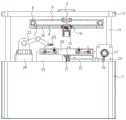
图1为本发明一种汽车塑料件焊接用具有旋转功能的生产设备正面结构示意图;1 is a schematic diagram of the front structure of a production equipment with a rotating function for welding of automotive plastic parts according to the present invention;
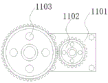
图2为本发明一种汽车塑料件焊接用具有旋转功能的生产设备同步齿轮与第一从动齿轮啮合结构内部结构示意图;2 is a schematic diagram of the internal structure of the meshing structure between the synchronizing gear and the first driven gear of a production equipment with a rotating function for welding automotive plastic parts according to the present invention;
图3为本发明一种汽车塑料件焊接用具有旋转功能的生产设备旋转盘内部结构示意图;3 is a schematic diagram of the internal structure of a rotary disk of a production equipment with a rotating function for welding automotive plastic parts according to the present invention;
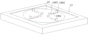
图4为本发明一种汽车塑料件焊接用具有旋转功能的生产设备工作台与固定机构结构示意图;4 is a schematic structural diagram of a workbench and a fixing mechanism of a production equipment with a rotating function for welding of automotive plastic parts according to the present invention;
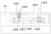
图5为本发明一种汽车塑料件焊接用具有旋转功能的生产设备固定机构颞部结构示意图。FIG. 5 is a schematic view of the structure of the temple of a fixing mechanism of a production equipment with a rotating function for welding of automobile plastic parts according to the present invention.
图中:1、底部机箱;2、支撑架;3、顶板;4、旋转柱;5、旋转盘;6、步进电机;7、控制器;8、同步带;9、滑块;10、滑轨;11、夹持机构;1101、马达;1102、同步齿轮;1103、第一从动齿轮;1104、旋转板;1105、活塞杆;1106、分流仓;1107、导流管;1108、充气囊;1109、轴承;12、工作台;13、从动轴;14、第二从动齿轮;15、从动杆;16、从动斜齿轮;17、同步斜齿轮;18、伺服电机;19、固定机构;1901、滑槽;1902、夹板;1903、螺母;1904、旋转杆;1905、螺纹;1906、第三从动齿轮;1907、凸钮;1908、齿条;20、底座;21、机械臂;22、激光焊接头。In the figure: 1. Bottom chassis; 2. Supporting frame; 3. Top plate; 4. Rotating column; 5. Rotating disc; 6. Stepper motor; 7. Controller; 8. Timing belt; 9. Slider; 10. Slide rail; 11. Clamping mechanism; 1101, Motor; 1102, Synchronous gear; 1103, First driven gear; 1104, Rotating plate; 1105, Piston rod; Airbag; 1109, Bearing; 12, Worktable; 13, Driven Shaft; 14, Second Driven Gear; 15, Driven Rod; 16, Driven Helical Gear; 17, Synchronous Helical Gear; 18, Servo Motor; 19 , fixing mechanism; 1901, chute; 1902, splint; 1903, nut; 1904, rotating rod; 1905, thread; 1906, third driven gear; 1907, knob; 1908, rack; 20, base; 21, Robotic arm; 22. Laser welding head.
具体实施方式Detailed ways
下面将结合本发明实施例中的附图,对本发明实施例中的技术方案进行清楚、完整地描述,显然,所描述的实施例仅仅是本发明一部分实施例,而不是全部的实施例,基于本发明中的实施例,本领域普通技术人员在没有做出创造性劳动前提下所获得的所有其他实施例,都属于本发明保护的范围。The technical solutions in the embodiments of the present invention will be clearly and completely described below with reference to the accompanying drawings in the embodiments of the present invention. Obviously, the described embodiments are only a part of the embodiments of the present invention, not all of the embodiments. The embodiments of the present invention, and all other embodiments obtained by those of ordinary skill in the art without creative work, fall within the protection scope of the present invention.
请参阅图1-5,本发明提供一种技术方案:一种汽车塑料件焊接用具有旋转功能的生产设备,包括底部机箱1, 底部机箱1的上表面对称设置有支撑架2,且支撑架2的顶部设置于顶板3四角的内部,顶板3的底部表面安装有旋转柱4,且旋转柱4的下方横穿旋转盘5的内部,旋转盘5的内部两侧设置有步进电机6,且步进电机6的右侧安装有控制器7,控制器7的内部连接有同步带8,且同步带8的下方连接有滑块9,滑块9的两端设置于滑轨10的内部,旋转盘5的外观形状呈圆形结构,且旋转盘5的内部为镂空装,旋转盘5与滑轨10之间为一体化机构,且滑轨10的长度尺寸和固定机构19的尺寸相一致,滑块9通过同步带8和控制器7与步进电机6之间构成移动结构,这样设置的作用是通过将步进电机6和同步带8设置于旋转盘5的内部,通过旋转盘5的设置,便于对步进电机6和控制器7起到一个固定支撑的作用,同时通过同步带8的设置,便于控制滑块9在滑轨10中进行位置移动,从而有利于夹持机构调节11在固定机构上方的位置。1-5, the present invention provides a technical solution: a production equipment with a rotating function for welding automotive plastic parts, comprising a bottom case 1, and a support frame 2 is symmetrically arranged on the upper surface of the bottom case 1, and the support frame The top of 2 is arranged in the interior of the four corners of the top plate 3, the bottom surface of the top plate 3 is provided with a rotating column 4, and the bottom of the rotating column 4 traverses the interior of the
且滑块9的内部安装有夹持机构11,且马达1101的输出端上安装有同步齿轮1102,同步齿轮1102的齿槽啮合连接有第一从动齿轮1103,且第一从动齿轮1103的齿孔内部横穿的连接杆一端设置有旋转板1104,旋转板1104的左侧表面安装有活塞杆1105,且活塞杆1105的底部连接有分流仓1106,分流仓1106的两端分别设置有导流管1107,且导流管1107的下方安装有充气囊1108,夹持机构11的外侧与滑块9的内部之间设置有轴承1109,夹持机构11的形状为圆柱形结构,且夹持机构11的上方表面滑块9的内部设置有圆环,且轴承1109的内圈和外圈分别与滑块9的内侧和夹持机构11的上方之间为焊接固定连接,夹持机构11通过轴承1109和滑块9之间构成可旋转结构,旋转板1104与第一从动齿轮1103通过连接杆之间相连接,且第一从动齿轮1103的尺寸大于同步齿轮1102,充气囊1108通过导流管1107和活塞杆1105之间为紧密连接,且充气囊1108通过旋转板1104带动活塞杆1105伸缩运作之间构成可充气结构,这样设置的作用是通过将夹持机构11的底部设置成镂空状态,便于将挂钩上方伸进夹持机构11的内部,同时通过在夹持机构11的内壁两安装充气囊1108,并且通过旋转板1104带动活塞杆1105运作,对充气囊1108的内部进行充气,从而使充气囊1108在充气的同时能够紧密贴合挂钩,从而有利于不同形状的挂钩进行夹持。A
底部机箱1的上方表面设置有工作台12,且工作台12的内部居中安装有从动轴13,从动轴13的上方设置有第二从动齿轮14,且第二从动齿轮14的右侧安装有从动杆15,从动杆15的两端对称设置有从动斜齿轮16,且从动杆15的右侧从动斜齿轮16上方齿槽啮合连接诶有同步斜齿轮17,同步斜齿轮17的齿孔与伺服电机18的输出端相连接,工作台12和固定机构19之间为活动连接,且第二从动齿轮14和从动杆15与从动斜齿轮16之间为活动啮合连接,第二从动齿轮14和从动轴13之间为固定连接,且从动轴13的顶部与工作台12的内部之间为活动丽连接,固定机构19通过从动轴13和从动杆15和伺服电机18之间构成可旋转结构,这样设置的作用是通过将从动轴13设置于工作台12的内部,通过将从动轴13的上方与固定机构19底部之间焊接固定,便于对固定机构19支撑的同时可同步旋转,并且通过伺服电机18和从动杆15的设置,便于带动第二从动齿轮14和从动斜齿轮16之间的啮合旋转,从而有利于固定19机构进行旋转。A
且工作台12的上方设置有固定机构19,且滑槽1901的内部横穿设置有夹板1902,夹板1902的底部焊接有螺母1903,且螺母1903的内部横穿设置有旋转杆1904,旋转杆1904的右侧螺母1903下方设置有螺纹1905,且旋转杆1904的左侧设置有第三从动齿轮1906,固定机构19的表面中心线两侧对称设置有凸钮1907,且凸钮1907的一侧设置有齿条1908,固定机构19上中心线对称呈十字机构设设置有凸钮1907和滑槽1901,且滑槽1901和固定机构19之间为一体化结构,固定机构19的形状为圆形结构,凸钮1907与齿条1908之间为一体化机构,且旋转杆1904右侧与螺纹1905之间为一体化结构,夹板1902通过螺母1903和旋转杆1904之间为活动连接,且夹板1902通过按压凸钮1907和旋转杆1904与螺母1903之间构成可旋夹持结构,这样设置的作用是通过将凸钮1907和夹板1902设置于固定机构19的表面,通过凸钮1907的设置,便于在下压的过程中带动齿条1908和第三从动齿轮1906的啮合旋转,并且通过旋转杆1904的设置,便于螺母1903在螺纹1905上进行啮合旋转移动,从而有利于夹板1902对面板四周进行固定夹持。Moreover, a
工作台12的左侧底部机箱1的表面安装有底座20,且底座20的上方连接有机械臂21,机械臂21的右侧内部设置有激光焊接头22。A
工作原理:对于这类的汽车塑料件焊接用具有旋转功能的生产设备,首先将需要焊接的面板摆放在工作台12上的固定机构19的上方,通过按下面板使凸钮1907开始下降,而齿条1908跟随凸钮1907下降的同时通过齿槽啮合连接带动第三从动齿轮1906同步旋转,这样设置在第三从动齿轮1906齿孔中安装的旋转杆1904开始带动螺纹1905上的螺母1903开始滑动,这样夹板1902便随着滑槽1901开始向内收缩将面板夹持固定。Working principle: For this type of production equipment with rotating function for welding of automotive plastic parts, first place the panel to be welded above the fixing
当面板被固定后将夹持机构11便通过旋转盘5内部设置的步进电机6和控制器7,带着滑块9在滑轨10上移动,将夹持机构11移至到面板上需要焊接的位置,随后将挂钩的呈倒立结构使焊接面与面板表面对齐放入夹持机构11的内部,然后控制夹持机构11内部马达1101开始运作带动与输出端同步齿轮1102啮合连接的第一从动齿轮1103开始旋转,这样旋转板1104便带动活塞杆1105开始做活塞运动,这样便是气体通过分流仓1106进入到两端设置的导流管1107中,从而使充气囊1108开始充气鼓起将挂钩进贴合夹持固定,激光焊接头22便通过机械臂21对面板和挂钩之间进行焊接,而设置的底部机箱1上的伺服电机18开始带动同步斜齿轮17旋转,这样从动杆15便通过两端设置的从动斜齿轮16动力传递开始同步旋转,这样便是从动轴13通过第二从动齿轮14开始旋转,这样固定机构19便开始旋转使激光焊接头22对面板和挂钩之间进行焊接固定,当焊接完成后只需要将夹板1902向外移动,将面板从固定机构19拿出即可,这样就完成了整个汽车塑料件焊接用具有旋转功能的生产设备的使用过程。After the panel is fixed, the
尽管已经示出和描述了本发明的实施例,对于本领域的普通技术人员而言,可以理解在不脱离本发明的原理和精神的情况下可以对这些实施例进行多种变化、修改、替换和变型,本发明的范围由所附权利要求及其等同物限定。Although embodiments of the present invention have been shown and described, it will be understood by those skilled in the art that various changes, modifications, and substitutions can be made in these embodiments without departing from the principle and spirit of the invention and modifications, the scope of the invention is defined by the appended claims and their equivalents.
Claims (9)
Priority Applications (1)
| Application Number | Priority Date | Filing Date | Title |
|---|---|---|---|
| CN202010852632.6A CN112123788A (en) | 2020-08-22 | 2020-08-22 | Production facility that has rotation function for welding of car working of plastics |
Applications Claiming Priority (1)
| Application Number | Priority Date | Filing Date | Title |
|---|---|---|---|
| CN202010852632.6A CN112123788A (en) | 2020-08-22 | 2020-08-22 | Production facility that has rotation function for welding of car working of plastics |
Publications (1)
| Publication Number | Publication Date |
|---|---|
| CN112123788A true CN112123788A (en) | 2020-12-25 |
Family
ID=73851088
Family Applications (1)
| Application Number | Title | Priority Date | Filing Date |
|---|---|---|---|
| CN202010852632.6A Withdrawn CN112123788A (en) | 2020-08-22 | 2020-08-22 | Production facility that has rotation function for welding of car working of plastics |
Country Status (1)
| Country | Link |
|---|---|
| CN (1) | CN112123788A (en) |
Cited By (1)
| Publication number | Priority date | Publication date | Assignee | Title |
|---|---|---|---|---|
| CN112959672A (en) * | 2021-02-05 | 2021-06-15 | 余巧琦 | Spot welding mechanism for mask machine |
-
2020
- 2020-08-22 CN CN202010852632.6A patent/CN112123788A/en not_active Withdrawn
Cited By (2)
| Publication number | Priority date | Publication date | Assignee | Title |
|---|---|---|---|---|
| CN112959672A (en) * | 2021-02-05 | 2021-06-15 | 余巧琦 | Spot welding mechanism for mask machine |
| CN112959672B (en) * | 2021-02-05 | 2022-12-30 | 江西源生狼和药业有限公司 | Spot welding mechanism with image recognition mechanism for mask machine |
Similar Documents
| Publication | Publication Date | Title |
|---|---|---|
| CN212949250U (en) | Production facility that has rotation function for welding of car working of plastics | |
| CN110549048A (en) | Rotary automatic welding robot and welding method thereof | |
| CN113245777A (en) | Flexible spot welding tool fixture for axle body | |
| CN112123788A (en) | Production facility that has rotation function for welding of car working of plastics | |
| CN120533287B (en) | Welding equipment for manufacturing inner handle of car door | |
| CN116275506A (en) | A laser welding multi-station welding station and its application method | |
| CN116460439A (en) | A kind of laser welding robot and its welding method | |
| CN114147329A (en) | Double-roller inner container roll welding equipment | |
| CN119703547A (en) | Double-station inverter welding equipment and using method thereof | |
| CN221211629U (en) | Automobile part overturning tool | |
| CN218225349U (en) | Three-axis hollow C-shaped positioner | |
| CN219521049U (en) | Welding clamping device for liquid storage drying bottle | |
| CN118682376A (en) | A high manganese steel automatic welding process | |
| CN213970843U (en) | High-precision clamp for valve plate machining | |
| CN212443699U (en) | Adjustable moving spot welding machine | |
| CN117300477A (en) | A welding station for processing car seat accessories | |
| CN223431175U (en) | A positioner | |
| CN218983784U (en) | Clamping and overturning device for welding | |
| CN222243053U (en) | Positioning device for powder plasma welding | |
| CN223718636U (en) | An automatic welding device for automotive parts | |
| CN222404062U (en) | A non-standard parts welding machine | |
| CN223265151U (en) | Assembly machine for torque limiter | |
| CN222095176U (en) | A welding and positioning fixture for telescopic forklift frame | |
| CN223130708U (en) | Automobile subframe welding positioning robot | |
| CN223776172U (en) | Positioning center mechanism for gear hobbing |
Legal Events
| Date | Code | Title | Description |
|---|---|---|---|
| PB01 | Publication | ||
| PB01 | Publication | ||
| SE01 | Entry into force of request for substantive examination | ||
| SE01 | Entry into force of request for substantive examination | ||
| WW01 | Invention patent application withdrawn after publication | ||
| WW01 | Invention patent application withdrawn after publication |
Application publication date: 20201225 |