CN112123798A - Computer special type bright film machine - Google Patents
Computer special type bright film machine Download PDFInfo
- Publication number
- CN112123798A CN112123798A CN202010997559.1A CN202010997559A CN112123798A CN 112123798 A CN112123798 A CN 112123798A CN 202010997559 A CN202010997559 A CN 202010997559A CN 112123798 A CN112123798 A CN 112123798A
- Authority
- CN
- China
- Prior art keywords
- punching
- cam
- connecting rod
- heads
- guide rail
- Prior art date
- Legal status (The legal status is an assumption and is not a legal conclusion. Google has not performed a legal analysis and makes no representation as to the accuracy of the status listed.)
- Granted
Links
Images



Classifications
-
- B—PERFORMING OPERATIONS; TRANSPORTING
- B29—WORKING OF PLASTICS; WORKING OF SUBSTANCES IN A PLASTIC STATE IN GENERAL
- B29C—SHAPING OR JOINING OF PLASTICS; SHAPING OF MATERIAL IN A PLASTIC STATE, NOT OTHERWISE PROVIDED FOR; AFTER-TREATMENT OF THE SHAPED PRODUCTS, e.g. REPAIRING
- B29C65/00—Joining or sealing of preformed parts, e.g. welding of plastics materials; Apparatus therefor
- B29C65/74—Joining or sealing of preformed parts, e.g. welding of plastics materials; Apparatus therefor by welding and severing, or by joining and severing, the severing being performed in the area to be joined, next to the area to be joined, in the joint area or next to the joint area
- B29C65/745—Joining or sealing of preformed parts, e.g. welding of plastics materials; Apparatus therefor by welding and severing, or by joining and severing, the severing being performed in the area to be joined, next to the area to be joined, in the joint area or next to the joint area using a single unit having both a severing tool and a welding tool
-
- B—PERFORMING OPERATIONS; TRANSPORTING
- B26—HAND CUTTING TOOLS; CUTTING; SEVERING
- B26D—CUTTING; DETAILS COMMON TO MACHINES FOR PERFORATING, PUNCHING, CUTTING-OUT, STAMPING-OUT OR SEVERING
- B26D5/00—Arrangements for operating and controlling machines or devices for cutting, cutting-out, stamping-out, punching, perforating, or severing by means other than cutting
- B26D5/08—Means for actuating the cutting member to effect the cut
- B26D5/16—Cam means
-
- B—PERFORMING OPERATIONS; TRANSPORTING
- B26—HAND CUTTING TOOLS; CUTTING; SEVERING
- B26D—CUTTING; DETAILS COMMON TO MACHINES FOR PERFORATING, PUNCHING, CUTTING-OUT, STAMPING-OUT OR SEVERING
- B26D7/00—Details of apparatus for cutting, cutting-out, stamping-out, punching, perforating, or severing by means other than cutting
- B26D7/06—Arrangements for feeding or delivering work of other than sheet, web, or filamentary form
-
- B—PERFORMING OPERATIONS; TRANSPORTING
- B26—HAND CUTTING TOOLS; CUTTING; SEVERING
- B26D—CUTTING; DETAILS COMMON TO MACHINES FOR PERFORATING, PUNCHING, CUTTING-OUT, STAMPING-OUT OR SEVERING
- B26D7/00—Details of apparatus for cutting, cutting-out, stamping-out, punching, perforating, or severing by means other than cutting
- B26D7/26—Means for mounting or adjusting the cutting member; Means for adjusting the stroke of the cutting member
- B26D7/2614—Means for mounting the cutting member
-
- B—PERFORMING OPERATIONS; TRANSPORTING
- B26—HAND CUTTING TOOLS; CUTTING; SEVERING
- B26D—CUTTING; DETAILS COMMON TO MACHINES FOR PERFORATING, PUNCHING, CUTTING-OUT, STAMPING-OUT OR SEVERING
- B26D7/00—Details of apparatus for cutting, cutting-out, stamping-out, punching, perforating, or severing by means other than cutting
- B26D7/27—Means for performing other operations combined with cutting
- B26D7/32—Means for performing other operations combined with cutting for conveying or stacking cut product
-
- B—PERFORMING OPERATIONS; TRANSPORTING
- B26—HAND CUTTING TOOLS; CUTTING; SEVERING
- B26F—PERFORATING; PUNCHING; CUTTING-OUT; STAMPING-OUT; SEVERING BY MEANS OTHER THAN CUTTING
- B26F1/00—Perforating; Punching; Cutting-out; Stamping-out; Apparatus therefor
- B26F1/24—Perforating by needles or pins
-
- B—PERFORMING OPERATIONS; TRANSPORTING
- B29—WORKING OF PLASTICS; WORKING OF SUBSTANCES IN A PLASTIC STATE IN GENERAL
- B29C—SHAPING OR JOINING OF PLASTICS; SHAPING OF MATERIAL IN A PLASTIC STATE, NOT OTHERWISE PROVIDED FOR; AFTER-TREATMENT OF THE SHAPED PRODUCTS, e.g. REPAIRING
- B29C65/00—Joining or sealing of preformed parts, e.g. welding of plastics materials; Apparatus therefor
- B29C65/48—Joining or sealing of preformed parts, e.g. welding of plastics materials; Apparatus therefor using adhesives, i.e. using supplementary joining material; solvent bonding
-
- B—PERFORMING OPERATIONS; TRANSPORTING
- B29—WORKING OF PLASTICS; WORKING OF SUBSTANCES IN A PLASTIC STATE IN GENERAL
- B29C—SHAPING OR JOINING OF PLASTICS; SHAPING OF MATERIAL IN A PLASTIC STATE, NOT OTHERWISE PROVIDED FOR; AFTER-TREATMENT OF THE SHAPED PRODUCTS, e.g. REPAIRING
- B29C65/00—Joining or sealing of preformed parts, e.g. welding of plastics materials; Apparatus therefor
- B29C65/78—Means for handling the parts to be joined, e.g. for making containers or hollow articles, e.g. means for handling sheets, plates, web-like materials, tubular articles, hollow articles or elements to be joined therewith; Means for discharging the joined articles from the joining apparatus
- B29C65/7858—Means for handling the parts to be joined, e.g. for making containers or hollow articles, e.g. means for handling sheets, plates, web-like materials, tubular articles, hollow articles or elements to be joined therewith; Means for discharging the joined articles from the joining apparatus characterised by the feeding movement of the parts to be joined
-
- B—PERFORMING OPERATIONS; TRANSPORTING
- B29—WORKING OF PLASTICS; WORKING OF SUBSTANCES IN A PLASTIC STATE IN GENERAL
- B29C—SHAPING OR JOINING OF PLASTICS; SHAPING OF MATERIAL IN A PLASTIC STATE, NOT OTHERWISE PROVIDED FOR; AFTER-TREATMENT OF THE SHAPED PRODUCTS, e.g. REPAIRING
- B29C65/00—Joining or sealing of preformed parts, e.g. welding of plastics materials; Apparatus therefor
- B29C65/78—Means for handling the parts to be joined, e.g. for making containers or hollow articles, e.g. means for handling sheets, plates, web-like materials, tubular articles, hollow articles or elements to be joined therewith; Means for discharging the joined articles from the joining apparatus
- B29C65/7897—Means for discharging the joined articles from the joining apparatus
-
- D—TEXTILES; PAPER
- D06—TREATMENT OF TEXTILES OR THE LIKE; LAUNDERING; FLEXIBLE MATERIALS NOT OTHERWISE PROVIDED FOR
- D06Q—DECORATING TEXTILES
- D06Q1/00—Decorating textiles
- D06Q1/10—Decorating textiles by treatment with, or fixation of, a particulate material, e.g. mica, glass beads
-
- B—PERFORMING OPERATIONS; TRANSPORTING
- B29—WORKING OF PLASTICS; WORKING OF SUBSTANCES IN A PLASTIC STATE IN GENERAL
- B29L—INDEXING SCHEME ASSOCIATED WITH SUBCLASS B29C, RELATING TO PARTICULAR ARTICLES
- B29L2031/00—Other particular articles
- B29L2031/48—Wearing apparel
Landscapes
- Engineering & Computer Science (AREA)
- Mechanical Engineering (AREA)
- Life Sciences & Earth Sciences (AREA)
- Forests & Forestry (AREA)
- Textile Engineering (AREA)
- Treatment Of Fiber Materials (AREA)
- Perforating, Stamping-Out Or Severing By Means Other Than Cutting (AREA)
Abstract
Description
技术领域technical field
本发明涉及电脑特种亮片机。The invention relates to a computer special sequin machine.
背景技术Background technique
现有的亮片机大多时将形状颜色定型好的亮片通过热粘的形式固定在片衣上的,或将亮片中间冲孔后缝在片衣上,这两种形式的亮片加工都较复杂,加工效率较低,同时对亮片的形状大小有限制,无法加工尺寸过小的亮片。Most of the existing sequin machines fix the sequins with a good shape and color on the sheet coat by hot sticking, or punch holes in the middle of the sequins and then sew them on the sheet coat, both of which are more complicated to process the sequins. The processing efficiency is low, and the shape and size of the sequins are limited, and the sequins with too small size cannot be processed.
发明内容SUMMARY OF THE INVENTION
为了克服上述存在的不足,本发明提供了一种加工效率高、加工稳定可靠、可适用于各种不同形状大小亮片的电脑特种亮片机。In order to overcome the above-mentioned shortcomings, the present invention provides a computer special sequin machine with high processing efficiency, stable and reliable processing, and suitable for various shapes and sizes of sequins.
为了实现以上目的,本发明采取的技术方案是:电脑特种亮片机,包括机架、工作台、机头和控制单元,所述控制单元通过电机控制工作台沿水平面前后左右移动,所述机头固定在机架上并通过控制单元带动工作,所述机头包括凸轮、冲压装置、供料装置、收料装置和水平导轨,所述凸轮固定在水平导轨上,控制单元通过电机控制凸轮沿水平导轨横向移动和转动,凸轮连接设有冲压连杆和收料连杆,所述冲压连杆带动冲压装置往复运动,所述收料连杆带动收料装置往复运动,所述冲压装置包括数量一致的多个冲针和冲头,所述冲头竖直方向上设有冲孔,冲头水平方向上设有进料口和出料口,所述冲针与冲孔对应配合,冲针上设有冲针弹簧,所述冲针弹簧提供冲针向上的弹簧回复力,所述供料装置包括亮片带盘和带状亮片条,所述带状亮片条绕在亮片带盘,并延伸到冲头的进料口内,所述收料装置包括数量一致的多个压头、主动压辊和从动压辊,所述压头通过棘轮与主动压辊相配合,压头一端与收料连杆相配合,压头另一端设有回复弹簧,所述回复弹簧提供压头向上的弹簧回复力,所述出料口位置对应主动压辊和从动压辊相压紧的位置,冲针和压头数量相一致均与水平导轨平行设置,并且位置一一对应。In order to achieve the above purpose, the technical solution adopted in the present invention is: a computer special sequin machine, including a frame, a workbench, a machine head and a control unit, the control unit controls the workbench to move left and right along the horizontal front, back, and rear through a motor, and the machine head Fixed on the frame and driven to work by the control unit, the machine head includes a cam, a punching device, a feeding device, a receiving device and a horizontal guide rail, the cam is fixed on the horizontal guide rail, and the control unit controls the cam along the horizontal rail through the motor. The guide rail moves and rotates laterally, and the cam is connected with a punching link and a receiving link. The punching link drives the punching device to reciprocate, and the receiving link drives the receiving device to reciprocate. The punching device includes a consistent number of There are a plurality of punching needles and punches, the punches are provided with punching holes in the vertical direction, and the punching head is provided with a feeding port and a discharging port in the horizontal direction. A punching needle spring is provided, and the punching needle spring provides a spring restoring force for the punching needle upward. In the feeding port of the punch, the receiving device includes a plurality of pressure heads, active pressure rollers and driven pressure rollers in the same number. The rods are matched with each other, and the other end of the indenter is provided with a return spring. The return spring provides the spring return force of the indenter upward. The position of the discharge port corresponds to the position where the active pressure roller and the driven pressure roller are pressed together. The same number of indenters are arranged in parallel with the horizontal guide rail, and the positions correspond one by one.
本发明提供的有益效果是:在电机驱动下,机头的凸轮通过冲压连杆先带动冲压装置,可以将冲针向下插入冲头的冲孔内,将沿冲头进料口进入的带状亮片条处于冲孔位置的部分,向下冲断并挤压粘到处于工作台上的带胶性的片衣对应位置,再通过片衣在工作台上受控制单元的控制沿水平面前后左右移动到所需要的下一个工序位置,即可完成一片亮片的冲压加工,这种加工方式可以实现各种不同大小尺寸以及不同形状的亮片加工,只需要将冲针的端面形状换成所需要的尺寸和形状,为了使用方便,设置多个端面为不同尺寸和形状的冲针,同时对应设置冲头、压头、、主动压辊和从动压辊,直接选定所需要的冲针即可,完成一次亮片加工后,同一个凸轮通过收料连杆再带动压头向下运动,从而使压头通过棘轮带动主动压辊转动,此过程中主动压辊和从动压辊一起向后转动,将压紧的已被冲针冲过的带状亮片条从出料口向后拉动一个工位,使带状亮片条整体进一个工位,为下一次冲压工序做好准备,在收料工序时,冲针在冲针弹簧的作用下向上回位,而在冲压工序时,压头在回复弹簧的作用下也向上回位,此过程中由于棘轮的作用,使得主动压辊打滑,并不会带动带状亮片条反向移动,如此往复加工效率高,相比通过两个电机分别控制冲压和收料两个工序,这种通过同一个凸轮实现冲压和收料两个工序间歇运动,可以达到零失误,并不会因为电机的精度使误差慢慢累积,可以有效地避免了在冲压工序进行时,收料工序也同时在进行,最后造成工序错乱。The beneficial effects provided by the present invention are: under the drive of the motor, the cam of the machine head drives the punching device first through the punching connecting rod, so that the punching needle can be inserted into the punching hole of the punching head downward, and the belt entering along the feeding port of the punching head can be inserted into the punching hole of the punching head. The part of the sequin strip at the punching position is punched down and squeezed to the corresponding position of the adhesive sheet coat on the workbench, and then the sheet coat is controlled by the control unit on the workbench along the horizontal front, back, left and right. Move to the required next process position to complete the stamping of a piece of sequins. This processing method can realize the processing of sequins of various sizes and shapes. It only needs to change the shape of the end face of the punching needle to the desired one. Size and shape, for the convenience of use, set a plurality of punching needles with different sizes and shapes, and set corresponding punches, indenters, active pressing rollers and driven pressing rollers, and directly select the required punching needles. , After finishing a sequin processing, the same cam drives the pressure head to move down through the receiving link, so that the pressure head drives the active pressure roller to rotate through the ratchet wheel. During this process, the active pressure roller and the driven pressure roller rotate backward together. , Pull the pressed ribbon-shaped sequins that have been punched by the punching needle backwards from the discharge port to a station, so that the ribbon-shaped sequins as a whole enter a station, and prepare for the next punching process. During the process, the punching needle returns upward under the action of the punching needle spring, and during the punching process, the indenter also returns upward under the action of the return spring. It will not drive the ribbon-shaped sequins to move in the opposite direction, so the reciprocating processing efficiency is high. Compared with the two processes of stamping and receiving through two motors, this kind of intermittent movement of the two processes of stamping and receiving through the same cam, Zero errors can be achieved, and errors will not be accumulated slowly due to the precision of the motor, which can effectively avoid the process of chaotic processes during the stamping process and the receiving process at the same time.
进一步的,所述压头连接有调节螺钉,所述调节螺钉调节压头与收料连杆相抵接的初始位置,由于凸轮带动收料连杆向下的最大行程是固定的,通过调节螺钉的调节压头与收料连杆相抵接的初始位置,从而调节压头被收料连杆带动的行程,进而调节主动压辊和从动压辊带动带状亮片条进位的行程,通过这种调节,在冲针端面尺寸小时(即所需加工亮片尺寸小),收料的进位行程也需要调小,才可以更有效的利用带状亮片条,不造成浪费。Further, the pressure head is connected with an adjustment screw, and the adjustment screw adjusts the initial position where the pressure head abuts against the receiving connecting rod. Since the cam drives the receiving connecting rod downward, the maximum stroke is fixed. Adjust the initial position of the indenter abutting against the receiving link, so as to adjust the stroke of the indenter driven by the receiving link, and then adjust the stroke of the active pressure roller and the driven pressure roller to drive the belt-shaped sequin strips to move, through this adjustment , When the size of the end face of the punching needle is small (that is, the size of the sequins to be processed is small), the carry-in stroke of the receiving material also needs to be reduced, so that the ribbon sequins can be used more effectively without waste.
进一步的,所述工作台包括四周固定框和橡胶材质的中间弹性布,相比处于固定水平面的硬台面,通过橡胶材质的中间弹性布,可以使冲压到片衣上亮片更好的粘接在片衣上,而不会造成冲压不到位或冲压过头造成顶针等现象。Further, the worktable includes a surrounding fixed frame and an intermediate elastic cloth made of rubber material. Compared with a hard table surface on a fixed horizontal plane, the intermediate elastic cloth made of rubber material can make the sequins punched onto the piece of clothing better adhere to the surface. On the film, without causing the punching in place or punching too much to cause the thimble and other phenomena.
进一步的,所述冲压连杆上设有连接头,所述连接头上设有凹陷,所述冲针上设有凸块,所述凸块与凹陷相配合,通过连接头上的凹陷与冲针上的凸块相配合,可以在选择不同的冲针时,只需要沿水平导轨移动凸轮和冲压连杆即可,这样的结构使得冲针的选择以及更换都更简单快捷。Further, the punching connecting rod is provided with a connecting head, the connecting head is provided with a concave, and the punching needle is provided with a convex block, and the convex block is matched with the concave, and the concave and punched through the connecting head. The protrusions on the needles are matched, so that when selecting different punching needles, it is only necessary to move the cam and punching link along the horizontal guide rail. This structure makes the selection and replacement of punching needles simpler and faster.
进一步的,所述凸轮上设有同轴转动的外凸轮和内凸轮,所述外凸轮带动冲压连杆往复运动,所述内凸轮带动收料连杆往复运动,设置外凸轮和内凸轮,并且使外凸轮推动冲压连杆时,内凸轮与收料连杆处于未配合状态,反之在内凸轮推动收料连杆时,外凸轮与冲压连杆处于未配合状态,这样的结构更简单合理。Further, the cam is provided with an outer cam and an inner cam that rotate coaxially, the outer cam drives the punching connecting rod to reciprocate, the inner cam drives the reciprocating movement of the receiving link, the outer cam and the inner cam are arranged, and When the outer cam pushes the punching link, the inner cam and the receiving link are in a non-cooperating state, on the contrary, when the inner cam pushes the receiving link, the outer cam and the punching link are in a non-cooperating state, and this structure is simpler and more reasonable.
进一步的,所述出料口后端设有导向管,所述导向管连接出料口与主动压辊和从动压辊相压紧的位置,通过导向管将带状亮片条从出料口引到主动压辊和从动压辊相压紧的位置,可以提高收料的稳定性,可以避免收料时带状亮片条胡乱缠绕起来。Further, the rear end of the discharge port is provided with a guide tube, and the guide tube is connected to the position where the discharge port is pressed by the active pressure roller and the driven pressure roller, and the ribbon-shaped sequins are guided from the discharge port through the guide tube. Lead to the position where the active pressure roller and the driven pressure roller are pressed together, which can improve the stability of the material receiving, and can avoid the random winding of the ribbon-shaped sequins during the material receiving.
下面结合附图和实施例对本发明作进一步详细介绍。The present invention will be further described in detail below with reference to the accompanying drawings and embodiments.
附图说明Description of drawings
图1是本发明提供的电脑特种亮片机的结构示意图。1 is a schematic structural diagram of a computer special sequin machine provided by the present invention.
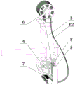
图2是图1中机头的结构示意图。FIG. 2 is a schematic structural diagram of the handpiece in FIG. 1 .
图3是图2中去掉供料装置后的结构示意图。FIG. 3 is a schematic view of the structure of FIG. 2 after removing the feeding device.
图4是图3另一角度示意图。FIG. 4 is another perspective view of FIG. 3 .
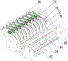
图5是图3中收料装置和冲头的结构示意图。FIG. 5 is a schematic structural diagram of the receiving device and the punch in FIG. 3 .
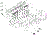
图6是图5另一角度示意图。FIG. 6 is another perspective view of FIG. 5 .
具体实施方式Detailed ways
如图1-6所示,本发明提供的电脑特种亮片机,包括机架1、工作台2、机头3和控制单元,所述控制单元通过电机控制工作台2沿水平面前后左右移动,所述机头3固定在机架1上并通过控制单元带动工作,所述机头3包括凸轮4、冲压装置5、供料装置6、收料装置7和水平导轨8,所述凸轮4固定在水平导轨8上,控制单元通过电机控制凸轮4沿水平导轨8横向移动和转动,凸轮4连接设有冲压连杆41和收料连杆42,所述冲压连杆41带动冲压装置5往复运动,所述收料连杆42带动收料装置7往复运动,所述冲压装置5包括数量一致的多个冲针51和冲头52,所述冲头52竖直方向上设有冲孔53,冲头52水平方向上设有进料口54和出料口55,所述冲针51与冲孔53对应配合,冲针51上设有冲针弹簧56,所述冲针弹簧56提供冲针51向上的弹簧回复力,所述供料装置6包括亮片带盘61和带状亮片条62,所述带状亮片条62绕在亮片带盘61,并延伸到冲头52的进料口54内,所述收料装置7包括数量一致的多个压头71、主动压辊72和从动压辊73,所述压头71通过棘轮74与主动压辊72相配合,压头71一端与收料连杆42相配合,压头71另一端设有回复弹簧75,所述回复弹簧75提供压头71向上的弹簧回复力,所述出料口55位置对应主动压辊72和从动压辊73相压紧的位置,冲针51和压头71数量相一致均与水平导轨8平行设置,并且位置一一对应,所述压头71连接有调节螺钉76,所述调节螺钉76调节压头71与收料连杆42相抵接的初始位置,所述工作台2包括四周固定框21和橡胶材质的中间弹性布22,所述冲压连杆41上设有连接头9,所述连接头9上设有凹陷10,所述冲针51上设有凸块11,所述凸块11与凹陷10相配合,所述凸轮4上设有同轴转动的外凸轮12和内凸轮13,所述外凸轮12带动冲压连杆41往复运动,所述内凸轮13带动收料连杆42往复运动,所述出料口54后端设有导向管56,所述导向管56连接出料口54与主动压辊72和从动压辊73相压紧的位置。As shown in Figures 1-6, the computer special sequin machine provided by the present invention includes a
Claims (6)
Priority Applications (1)
| Application Number | Priority Date | Filing Date | Title |
|---|---|---|---|
| CN202010997559.1A CN112123798B (en) | 2020-09-21 | 2020-09-21 | Computer special sequin machine |
Applications Claiming Priority (1)
| Application Number | Priority Date | Filing Date | Title |
|---|---|---|---|
| CN202010997559.1A CN112123798B (en) | 2020-09-21 | 2020-09-21 | Computer special sequin machine |
Publications (2)
| Publication Number | Publication Date |
|---|---|
| CN112123798A true CN112123798A (en) | 2020-12-25 |
| CN112123798B CN112123798B (en) | 2025-07-15 |
Family
ID=73841871
Family Applications (1)
| Application Number | Title | Priority Date | Filing Date |
|---|---|---|---|
| CN202010997559.1A Active CN112123798B (en) | 2020-09-21 | 2020-09-21 | Computer special sequin machine |
Country Status (1)
| Country | Link |
|---|---|
| CN (1) | CN112123798B (en) |
Citations (18)
| Publication number | Priority date | Publication date | Assignee | Title |
|---|---|---|---|---|
| BE721937A (en) * | 1968-10-07 | 1969-03-14 | ||
| US3713406A (en) * | 1971-06-23 | 1973-01-30 | Singer Co | Automatic machine for sewing pocket pieces and the like to garments |
| KR200176696Y1 (en) * | 1999-10-25 | 2000-04-15 | 박찬수 | An apparatus for manufacturing spangle |
| JP2000279671A (en) * | 1999-03-30 | 2000-10-10 | Juki Corp | Sewing machine presser foot device |
| WO2001045616A1 (en) * | 1999-12-21 | 2001-06-28 | The Procter & Gamble Company | Laminate web comprising an apertured layer and method for manufacture thereof |
| KR20020081827A (en) * | 2001-04-19 | 2002-10-30 | 한광수 | Manufacturing method of spangle textile |
| KR20030026953A (en) * | 2003-02-28 | 2003-04-03 | 주식회사 제이디씨텍 | a ultrasonic automatic machining system |
| KR20040077622A (en) * | 2004-08-14 | 2004-09-04 | 장용기 | The stitching devise have spangle standard different in embroidery machine |
| KR100479705B1 (en) * | 2004-11-08 | 2005-03-31 | 장우진 | Apparatus for making spangle |
| KR100783015B1 (en) * | 2007-05-14 | 2007-12-06 | 박인원 | Sequin Forming and Attaching Device for Garment with Control of Sequin Spacing |
| KR20140065170A (en) * | 2012-11-21 | 2014-05-29 | 김원조 | Hammer for spangle needles |
| CN205466526U (en) * | 2016-01-05 | 2016-08-17 | 任杰 | Files are bound and are used perforating device |
| KR101653329B1 (en) * | 2016-05-03 | 2016-09-09 | 류영철 | Punching presses for spangle motive manufacturing equipment |
| CN207373309U (en) * | 2018-01-15 | 2018-05-18 | 绍兴市郑顺绣品有限公司 | A kind of paillette stamping machine |
| CN208131856U (en) * | 2018-04-16 | 2018-11-23 | 东莞市德景五金钮扣有限公司 | A special button stamping machine for baby safety |
| CN210146732U (en) * | 2019-06-11 | 2020-03-17 | 成都远博安新能源科技有限公司 | Button type stamping edge covering machine |
| CN111203476A (en) * | 2020-03-06 | 2020-05-29 | 温州暗帕科技有限公司 | Sheet metal molding equipment |
| CN214082944U (en) * | 2020-09-21 | 2021-08-31 | 朱有旺 | Computer special type bright film machine |
-
2020
- 2020-09-21 CN CN202010997559.1A patent/CN112123798B/en active Active
Patent Citations (18)
| Publication number | Priority date | Publication date | Assignee | Title |
|---|---|---|---|---|
| BE721937A (en) * | 1968-10-07 | 1969-03-14 | ||
| US3713406A (en) * | 1971-06-23 | 1973-01-30 | Singer Co | Automatic machine for sewing pocket pieces and the like to garments |
| JP2000279671A (en) * | 1999-03-30 | 2000-10-10 | Juki Corp | Sewing machine presser foot device |
| KR200176696Y1 (en) * | 1999-10-25 | 2000-04-15 | 박찬수 | An apparatus for manufacturing spangle |
| WO2001045616A1 (en) * | 1999-12-21 | 2001-06-28 | The Procter & Gamble Company | Laminate web comprising an apertured layer and method for manufacture thereof |
| KR20020081827A (en) * | 2001-04-19 | 2002-10-30 | 한광수 | Manufacturing method of spangle textile |
| KR20030026953A (en) * | 2003-02-28 | 2003-04-03 | 주식회사 제이디씨텍 | a ultrasonic automatic machining system |
| KR20040077622A (en) * | 2004-08-14 | 2004-09-04 | 장용기 | The stitching devise have spangle standard different in embroidery machine |
| KR100479705B1 (en) * | 2004-11-08 | 2005-03-31 | 장우진 | Apparatus for making spangle |
| KR100783015B1 (en) * | 2007-05-14 | 2007-12-06 | 박인원 | Sequin Forming and Attaching Device for Garment with Control of Sequin Spacing |
| KR20140065170A (en) * | 2012-11-21 | 2014-05-29 | 김원조 | Hammer for spangle needles |
| CN205466526U (en) * | 2016-01-05 | 2016-08-17 | 任杰 | Files are bound and are used perforating device |
| KR101653329B1 (en) * | 2016-05-03 | 2016-09-09 | 류영철 | Punching presses for spangle motive manufacturing equipment |
| CN207373309U (en) * | 2018-01-15 | 2018-05-18 | 绍兴市郑顺绣品有限公司 | A kind of paillette stamping machine |
| CN208131856U (en) * | 2018-04-16 | 2018-11-23 | 东莞市德景五金钮扣有限公司 | A special button stamping machine for baby safety |
| CN210146732U (en) * | 2019-06-11 | 2020-03-17 | 成都远博安新能源科技有限公司 | Button type stamping edge covering machine |
| CN111203476A (en) * | 2020-03-06 | 2020-05-29 | 温州暗帕科技有限公司 | Sheet metal molding equipment |
| CN214082944U (en) * | 2020-09-21 | 2021-08-31 | 朱有旺 | Computer special type bright film machine |
Also Published As
| Publication number | Publication date |
|---|---|
| CN112123798B (en) | 2025-07-15 |
Similar Documents
| Publication | Publication Date | Title |
|---|---|---|
| US5367758A (en) | Method for manufacturing slide fastener coupling elements | |
| CN107186392A (en) | A kind of solar battery sheet automatic string welding machine welding shears alignment system | |
| CN214082944U (en) | Computer special type bright film machine | |
| CN114221197A (en) | Automatic assembling equipment for connector terminals | |
| CN108615603A (en) | A kind of stitch apparatus for shaping of network transformer | |
| CN209125104U (en) | A copper strip pulling device of a contact element welding machine | |
| US2444706A (en) | Slide fastener machine | |
| CN110744825A (en) | Pin inserting device for plastic parts | |
| CN115489800A (en) | A unilateral pad pasting equipment of little panel beating bracket for electronic product | |
| CN118910876B (en) | A new type of high-efficiency intelligent control clothing production sampling equipment | |
| CN209921777U (en) | An industrial label cutting system | |
| CN204148402U (en) | Punch press interval-automatic feed mechanism | |
| CN219932766U (en) | Ball feeding mechanism for assembling eccentric disc rolling bearing | |
| US2261552A (en) | Apparatus for making slide fasteners | |
| CN118249158A (en) | A stamping device and process for in-mold riveted wire clamping terminal | |
| CN112123798B (en) | Computer special sequin machine | |
| CN215366293U (en) | Ironing and embroidering integrated machine | |
| CN114771030B (en) | Breakable belt thermal insulation vertical bag making machine | |
| CN216938245U (en) | Novel press and rivet device | |
| CN104308022A (en) | Automatic intermittent feeding mechanism of punching machine | |
| CN211137416U (en) | Punching mechanism | |
| CN210911370U (en) | Pressing and buckling mechanism | |
| CN211897340U (en) | Automatic sewing mechanism for woven tape plastic sheet | |
| CN113020935A (en) | Feeding device for probe assembly production line | |
| CN222974536U (en) | Back panel tape laminating equipment |
Legal Events
| Date | Code | Title | Description |
|---|---|---|---|
| PB01 | Publication | ||
| PB01 | Publication | ||
| SE01 | Entry into force of request for substantive examination | ||
| SE01 | Entry into force of request for substantive examination | ||
| GR01 | Patent grant | ||
| GR01 | Patent grant |