CN112138363B - Anti-lock roller skating structure and anti-lock cross-country roller skating shoe - Google Patents
Anti-lock roller skating structure and anti-lock cross-country roller skating shoe Download PDFInfo
- Publication number
- CN112138363B CN112138363B CN202011020338.5A CN202011020338A CN112138363B CN 112138363 B CN112138363 B CN 112138363B CN 202011020338 A CN202011020338 A CN 202011020338A CN 112138363 B CN112138363 B CN 112138363B
- Authority
- CN
- China
- Prior art keywords
- column
- roller
- rotating shaft
- support column
- mounting plate
- Prior art date
- Legal status (The legal status is an assumption and is not a legal conclusion. Google has not performed a legal analysis and makes no representation as to the accuracy of the status listed.)
- Active
Links
- 230000015556 catabolic process Effects 0.000 claims description 7
- 230000003313 weakening effect Effects 0.000 claims description 2
- 238000005096 rolling process Methods 0.000 abstract description 4
- 230000001960 triggered effect Effects 0.000 abstract 1
- 238000010586 diagram Methods 0.000 description 5
- 238000000034 method Methods 0.000 description 4
- 230000008569 process Effects 0.000 description 3
- 230000008859 change Effects 0.000 description 2
- 230000004048 modification Effects 0.000 description 2
- 238000012986 modification Methods 0.000 description 2
- 244000025254 Cannabis sativa Species 0.000 description 1
- 238000010521 absorption reaction Methods 0.000 description 1
- 230000009471 action Effects 0.000 description 1
- 230000000694 effects Effects 0.000 description 1
- 238000009434 installation Methods 0.000 description 1
- 230000035939 shock Effects 0.000 description 1
Images


Classifications
-
- A—HUMAN NECESSITIES
- A63—SPORTS; GAMES; AMUSEMENTS
- A63C—SKATES; SKIS; ROLLER SKATES; DESIGN OR LAYOUT OF COURTS, RINKS OR THE LIKE
- A63C17/00—Roller skates; Skate-boards
- A63C17/04—Roller skates; Skate-boards with wheels arranged otherwise than in two pairs
- A63C17/06—Roller skates; Skate-boards with wheels arranged otherwise than in two pairs single-track type
-
- A—HUMAN NECESSITIES
- A63—SPORTS; GAMES; AMUSEMENTS
- A63C—SKATES; SKIS; ROLLER SKATES; DESIGN OR LAYOUT OF COURTS, RINKS OR THE LIKE
- A63C17/00—Roller skates; Skate-boards
- A63C17/14—Roller skates; Skate-boards with brakes, e.g. toe stoppers, freewheel roller clutches
- A63C17/1409—Roller skates; Skate-boards with brakes, e.g. toe stoppers, freewheel roller clutches contacting one or more of the wheels
-
- A—HUMAN NECESSITIES
- A63—SPORTS; GAMES; AMUSEMENTS
- A63C—SKATES; SKIS; ROLLER SKATES; DESIGN OR LAYOUT OF COURTS, RINKS OR THE LIKE
- A63C17/00—Roller skates; Skate-boards
- A63C17/22—Wheels for roller skates
Landscapes
- Footwear And Its Accessory, Manufacturing Method And Apparatuses (AREA)
Abstract
本发明涉及一种防抱死的轮滑结构及防抱死越野轮滑鞋,包括有环形滚轮和转动连接组件,其特征在于,所述环形滚轮可转动的设置在转动连接组件的转动端,所述转动连接组件可拆卸的连接有安装在鞋体下端面的防抱死的安全组件。当环形滚轮抱死时,由于环形滚轮与地面的摩擦力变大,将会触发安全组件,使该抱死的环形滚轮不再参与滚动,提高了越野轮滑的安全性,实用性强。
The invention relates to an anti-locking roller skating structure and an anti-locking off-road roller skate, comprising an annular roller and a rotating connecting assembly, characterized in that the annular roller is rotatably arranged on the rotating end of the rotating connecting assembly, and the The rotating connection assembly is detachably connected with an anti-lock safety assembly installed on the lower end face of the shoe body. When the ring roller is locked, because the friction between the ring roller and the ground increases, the safety component will be triggered, so that the locked ring roller no longer participates in rolling, which improves the safety of off-road roller skating and has strong practicability.
Description
技术领域technical field
本发明涉及越野轮滑鞋领域,特别是一种防抱死的轮滑结构及防抱死越野轮滑鞋。The invention relates to the field of off-road roller skates, in particular to an anti-lock roller skating structure and an anti-lock off-road roller skate.
背景技术Background technique
轮滑有很多汉化版本叫法,如旱冰、溜冰、滑冰、滚轴溜冰,但是到现在,统一叫轮滑。现在的轮滑鞋包括鞋体和轮子组件,是一种集娱乐和健身于一体的产品,受到很多人的喜爱,应用很广。越野轮滑鞋是主要用于在野外进行轮滑的轮滑鞋,大多数的使用工况为砂石路、草地和凹凸不平的公路等。There are many Chinese versions of roller skating, such as roller skating, skating, skating, roller skating, but now, it is called roller skating. Today's roller skates include shoe body and wheel components. They are a product that integrates entertainment and fitness. They are loved by many people and are widely used. Off-road roller skates are roller skates mainly used for roller skating in the wild. Most of the working conditions are gravel roads, grass and uneven roads.
现有的越野轮滑鞋其不足之处在于:1、由于越野轮滑的使用工况大多都是在不平的路面,所以当某一轮滑滚轮完全抱死时,使用者将会因为某一滚轮与地面的摩擦力的改变而导致使用者失去平衡,容易摔跤,现有的越野轮滑鞋不具备防止轮滑滚轮突然抱死的相关功能和结构;2、现有的越野轮滑鞋的滚轮刚性连接带动滚轮转动的轴承,当某一滚轮的轴承转动与其余的轴承转动不一致时,转动受阻的滚轮将会影响整个轮滑过程的流畅性。The shortcomings of the existing off-road roller skates are: 1. Since most of the working conditions of off-road roller skating are on uneven roads, when a roller of a roller skating is completely locked, the user will be caused by a roller and the ground. The change of friction force causes the user to lose balance and fall easily. The existing off-road roller skates do not have the relevant functions and structures to prevent the rollers from locking suddenly; 2. The rigid connection of the rollers of the existing off-road roller skates drives the rollers to rotate. When the rotation of the bearing of a roller is inconsistent with the rotation of the other bearings, the roller whose rotation is blocked will affect the smoothness of the entire roller skating process.
发明内容SUMMARY OF THE INVENTION
本发明的一个目的就是提供一种防抱死的轮滑结构,用于防止在越野轮滑的过程中,由于某一轮滑滚轮抱死而导致的轮滑鞋失效。An object of the present invention is to provide an anti-lock roller skating structure, which is used to prevent the roller skating shoes from failing due to the locking of a roller skating roller in the process of off-road roller skating.
本发明的该目的是通过这样的技术方案实现的,它包括有环形滚轮和转动连接组件,所述环形滚轮可转动的设置在转动连接组件的转动端,所述转动连接组件可拆卸的连接有安装在鞋体下端面的防抱死的安全组件。The purpose of the present invention is achieved through such a technical solution, which includes an annular roller and a rotating connection assembly, the annular roller is rotatably arranged on the rotating end of the rotating connection assembly, and the rotating connection assembly is detachably connected with a Anti-lock safety components installed on the lower end of the shoe body.
作为优选,所述安全组件包括:连接柱、通槽、第一转轴、安装在鞋体下端面的第一U形安装板;Preferably, the safety assembly includes: a connecting column, a through groove, a first rotating shaft, and a first U-shaped mounting plate mounted on the lower end face of the shoe body;
所述第一U形安装板两侧板之间连接有第一转轴,所述第一转轴转动设置在通槽内,所述通槽开设在连接柱上并贯穿连接柱两侧壁;A first rotating shaft is connected between the two side plates of the first U-shaped mounting plate, the first rotating shaft is rotatably arranged in a through groove, and the through groove is opened on the connecting column and penetrates through both side walls of the connecting column;
所述连接柱与第一转轴之间设置有可使连接柱与第一转轴相对转动的击穿模块,所述连接柱下端面可拆卸的连接其下方的转动连接组件。A breakdown module capable of relatively rotating the connecting column and the first rotating shaft is arranged between the connecting column and the first rotating shaft, and the lower end surface of the connecting column is detachably connected to the rotating connecting assembly below it.
作为优选,所述击穿模块包括第一导向柱、扇形穿刺柱、扇形导向槽、安全挡块、第一腔体、第二腔体;Preferably, the breakdown module includes a first guide column, a fan-shaped puncture column, a fan-shaped guide groove, a safety block, a first cavity, and a second cavity;
所述连接柱上与第一转轴的接触位置设置有扇形导向槽,所述扇形导向槽内固定有安全挡块,所述安全挡块将扇形导向槽分为第一腔体和第二腔体,所述第一导向柱一端连接第一转轴,另一端滑动设置在第一腔体内,所述扇形穿刺柱也位于第一腔体内且一端连接第一导向柱,另一端与安全挡块一端面贴合;A fan-shaped guide groove is set at the contact position between the connecting column and the first rotating shaft, and a safety block is fixed in the fan-shaped guide groove, and the safety block divides the fan-shaped guide groove into a first cavity and a second cavity. One end of the first guide column is connected to the first rotating shaft, and the other end is slidably arranged in the first cavity. fit;
所述安全挡块为可被扇形穿刺柱刺穿的材料。The safety block is a material that can be pierced by the fan-shaped piercing column.
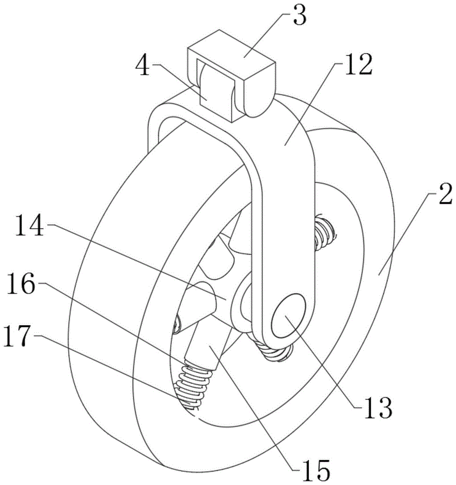
作为优选,所述转动连接组件包括:第二U形安装板、第二转轴、轴承;Preferably, the rotating connection assembly includes: a second U-shaped mounting plate, a second rotating shaft, and a bearing;
所述第二U形安装板的侧板位于第二U形安装板的顶板下方,所述第二U形安装板的顶板可拆卸的连接连接柱的下端面,所述第二U形安装板两侧板之间有环形滚轮,所述第二U形安装板两侧板通过第二转轴连接,所述第二转轴上设置有轴承,所述轴承通过若干个弹性组件连接环形滚轮内缘。The side plate of the second U-shaped mounting plate is located below the top plate of the second U-shaped mounting plate, the top plate of the second U-shaped mounting plate is detachably connected to the lower end surface of the connecting column, and the second U-shaped mounting plate There are annular rollers between the two side plates, the two side plates of the second U-shaped mounting plate are connected by a second rotating shaft, the second rotating shaft is provided with a bearing, and the bearing is connected to the inner edge of the annular roller through several elastic components.
作为优选,若干个所述弹性组件均包括:第一支撑柱、第二支撑柱、弹簧、限位导向孔;Preferably, several of the elastic components include: a first support column, a second support column, a spring, and a limit guide hole;
若干个所述弹性组件沿环形滚轮的轴线环形阵列,所述限位导向孔的轴线方向与环形滚轮的一个直径方向重合,所述限位导向孔开设在环形滚轮内壁,所述第二支撑柱一端通过限位柱可滑动的设置在限位导向孔内,所述第二支撑柱另一端固接第一支撑柱,所述第一支撑柱另一端固接轴承,所述第二支撑柱直径小于第一支撑柱,所述第二支撑柱上还套设有连接第一支撑柱和环形滚轮内壁的弹簧。A plurality of the elastic components are annularly arrayed along the axis of the annular roller, the axial direction of the limit guide hole coincides with a diameter direction of the annular roller, the limit guide hole is opened on the inner wall of the annular roller, and the second support column One end of the second support column is slidably arranged in the limit guide hole through the limit column, the other end of the second support column is fixed to the first support column, the other end of the first support column is fixed to the bearing, and the diameter of the second support column is Smaller than the first support column, the second support column is also sleeved with a spring connecting the first support column and the inner wall of the annular roller.
作为优选,所述弹性组件的数量大于等于三个。Preferably, the number of the elastic components is greater than or equal to three.
作为优选,所述安全挡块两侧壁均设置有环形弱化凹槽。Preferably, both side walls of the safety block are provided with annular weakening grooves.
本发明的另一个目的就是提供一种防抱死越野轮滑鞋,用于防止在越野轮滑过程中,由于某一轮滑滚轮抱死而导致使用者摔跤的越野轮滑鞋。Another object of the present invention is to provide an anti-lock off-road roller skating shoe, which is used to prevent a user from falling over due to the locking of a roller during off-road roller skating.
本发明的该目的是通过这样的技术方案实现的,它包括越野轮滑鞋体,所述越野轮滑鞋体下端面连接有一个以上的所述防抱死的轮滑结构。The purpose of the present invention is achieved through such a technical solution, which includes an off-road roller skating shoe body, and the lower end surface of the off-road roller skating shoe body is connected with more than one of the anti-lock roller skating structures.
由于采用了上述技术方案,本发明具有如下的优点:1、本申请通过设置安全组件,可在环形滚轮完全抱死的情况下,使连接柱与第一转轴发生相对转动,通过击穿模块中的扇形穿刺柱击穿安全挡块,使环形滚轮可沿第一转轴转动,达到抱死的环形滚轮不再参与轮滑鞋的滚动,从而防止使用者因为某一环形滚轮抱死而导致的失去平衡,避免摔跤;2、本申请通过弹性组件将越野轮滑的环形滚轮与轴承连接,当某一轴承与其余的轴承转动不一致时,环形滚轮将会在弹性组件的作用下减小与地面的摩擦力,保证整个轮滑过程的流畅性。Due to the adoption of the above-mentioned technical solutions, the present invention has the following advantages: 1. By setting the safety component in the present application, the connecting column and the first rotating shaft can be rotated relative to each other under the condition that the annular roller is completely locked. The fan-shaped puncture column breaks down the safety block, so that the ring roller can rotate along the first axis, so that the locked ring roller no longer participates in the rolling of the roller skates, thereby preventing the user from losing balance due to the locking of a ring roller. , to avoid falling; 2. In this application, the ring roller of the off-road roller skating is connected to the bearing through the elastic component. When a bearing rotates inconsistently with the rest of the bearings, the ring roller will reduce the friction with the ground under the action of the elastic component. , to ensure the smoothness of the entire roller skating process.
本发明的其他优点、目标和特征在某种程度上将在随后的说明书中进行阐述,并且在某种程度上,基于对下文的考察研究对本领域技术人员而言将是显而易见的,或者可以从本发明的实践中得到教导。本发明的目标和其他优点可以通过下面的说明书和权利要求书来实现和获得。Other advantages, objects and features of the present invention will be set forth in the description which follows, to the extent that will be apparent to those skilled in the art based on a study of the following, or may be learned from is taught in the practice of the present invention. The objectives and other advantages of the present invention may be realized and attained by the following description and claims.
附图说明Description of drawings
本发明的附图说明如下。The accompanying drawings of the present invention are described below.
图1为本发明的防抱死的轮滑结构示意图;1 is a schematic diagram of an anti-lock wheel skating structure of the present invention;
图2为本发明的防抱死的轮滑结构的前视图;2 is a front view of the anti-lock wheel skating structure of the present invention;
图3为本发明的A-A处的剖视图;Fig. 3 is the sectional view of the A-A place of the present invention;
图4为本发明的B处局部放大图;Fig. 4 is the partial enlarged view of B place of the present invention;
图5为本发明的第一U形安装板与第一转轴的连接示意图;5 is a schematic diagram of the connection between the first U-shaped mounting plate and the first rotating shaft of the present invention;
图6为本发明的连接柱和安全挡块的结构示意图;6 is a schematic structural diagram of the connecting column and the safety stop of the present invention;
图7为本发明的安全挡块的结构示意图;Fig. 7 is the structural schematic diagram of the safety stop of the present invention;
图8为本发明的防抱死越野轮滑鞋结构示意图。8 is a schematic structural diagram of an anti-lock off-road roller skate of the present invention.
图中:1.越野轮滑鞋体;2.环形滚轮;3.第一U形安装板;4.连接柱;5.通槽;6.第一转轴;7.第一导向柱;8.扇形穿刺柱;9.扇形导向槽;10.安全挡块;11.环形弱化凹槽;12.第二U形安装板;13.第二转轴;14.轴承;15.第一支撑柱;16.第二支撑柱;17.弹簧;18.限位导向孔;19.弹性组件;20.转动连接组件;21.安全组件;22.第一腔体;23.第二腔体。In the figure: 1. Off-road roller skate body; 2. Ring roller; 3. The first U-shaped mounting plate; 4. The connecting column; 9. Sector guide groove; 10. Safety stop; 11. Annular weakened groove; 12. Second U-shaped mounting plate; 13. Second shaft; 14. Bearing; 15. First support column; 16. 17. Spring; 18. Limiting guide hole; 19. Elastic component; 20. Rotating connection component; 21. Safety component; 22. First cavity; 23. Second cavity.
具体实施方式Detailed ways
下面结合附图和实施例对本发明作进一步说明。The present invention will be further described below with reference to the accompanying drawings and embodiments.
如图1至图7所示,一种防抱死的轮滑结构及防抱死越野轮滑鞋,包括有环形滚轮2和转动连接组件20,所述环形滚轮2可转动的设置在转动连接组件20的转动端,所述转动连接组件20可拆卸的连接有安装在鞋体下端面的防抱死的安全组件21。As shown in FIG. 1 to FIG. 7 , an anti-lock roller skating structure and anti-lock off-road roller skates include an
所述安全组件包括:连接柱4、通槽5、第一转轴6、安装在鞋体下端面的第一U形安装板3;所述第一U形安装板3两侧板之间连接有第一转轴6,所述第一转轴6转动设置在通槽5内,所述通槽5开设在连接柱4上并贯穿连接柱4两侧壁;所述连接柱4与第一转轴6之间设置有可使连接柱4与第一转轴6相对转动的击穿模块,所述连接柱4下端面可拆卸的连接其下方的转动连接组件;环形滚轮2抱死时,通过击穿模块,使连接柱4与第一转轴6发生相对转动,从而使环形滚轮2可绕第一转轴6转动,使抱死的环形滚轮2可以不参与越野轮滑运动。The safety assembly includes: a connecting
所述击穿模块包括第一导向柱7、扇形穿刺柱8、扇形导向槽9、安全挡块10、第一腔体22、第二腔体23;所述连接柱4上与第一转轴6的接触位置设置有扇形导向槽9,所述扇形导向槽9内固定有安全挡块10,所述安全挡块10将扇形导向槽9分为第一腔体22和第二腔体23,所述第一导向柱7一端连接第一转轴6,另一端滑动设置在第一腔体内,所述扇形穿刺柱8也位于第一腔体内且一端连接第一导向柱7,另一端与安全挡块10一端面贴合;所述安全挡块10为可被扇形穿刺柱8刺穿的材料;环形滚轮2抱死时,由于环形滚轮2与地面的摩擦力增大,使扇形穿刺柱8对安全挡块10施加的力增大,从而使扇形穿刺柱8可击穿安全挡块10,让连接柱4可与第一转轴6发生相对转动。The breakdown module includes a
所述转动连接组件包括:第二U形安装板12、第二转轴13、轴承14;所述第二U形安装板12的侧板位于第二U形安装板12的顶板下方,所述第二U形安装板12的顶板可拆卸的连接连接柱4的下端面,所述第二U形安装板12两侧板之间有环形滚轮2,所述第二U形安装板12两侧板通过第二转轴13连接,所述第二转轴13上设置有轴承14,所述轴承14通过若干个弹性组件19连接环形滚轮2内缘;轴承14可使环形滚轮2滚动,第二U形安装板12便于固定轴承14的位置。The rotating connection assembly includes: a second U-shaped mounting
若干个所述弹性组件均包括:第一支撑柱15、第二支撑柱16、弹簧17、限位导向孔18;若干个所述弹性组件沿环形滚轮2的轴线环形阵列,所述限位导向孔18的轴线方向与环形滚轮2的一个直径方向重合,所述限位导向孔18开设在环形滚轮2内壁,所述第二支撑柱16一端通过限位柱可滑动的设置在限位导向孔18内,所述第二支撑柱16另一端固接第一支撑柱15,所述第一支撑柱15另一端固接轴承14,所述第二支撑柱16直径小于第一支撑柱15,所述第二支撑柱16上还套设有连接第一支撑柱15和环形滚轮2内壁的弹簧17;当轴承14与轮滑鞋的其余轴承转动不一致时,越野轮滑鞋向前走时,由于弹簧17的作用,环形滚轮2将会向上移动,从而减少与地面的接触时间。Several of the elastic components include: a
所述弹性组件的数量大于等于三个;设置多个弹性组件减震支撑效果更强。The number of the elastic components is greater than or equal to three; setting a plurality of elastic components has a stronger shock absorption and support effect.
所述安全挡块10两侧壁均设置有环形弱化凹槽11;环形弱化凹槽11更利于扇形穿刺柱8击穿安全挡块10。Both side walls of the
如图8所示,一种防抱死越野轮滑鞋,包括越野轮滑鞋体1,所述越野轮滑鞋体1下端面连接有一个以上的所述防抱死的轮滑结构;可选择的在越野轮滑鞋上安装防抱死轮滑结构的数量,提高用户的可选择性。As shown in Figure 8, an anti-lock off-road roller skate includes an off-road roller
本发明中,环形滚轮2可在地面正常滚动时,环形滚轮2在第二U形安装板12滚动,第二U形安装板12通过安全组件连接在鞋体下端面;当环形滚轮2发生故障与轮滑鞋的其余环形滚轮滚动不一致时,此时发生故障的环形滚轮2由于与地面的摩擦力的改变,会使压缩弹簧17,使发生故障的环形滚轮2向上移动,从而脱离或减小与地面的摩擦力;当环形滚轮2完全失效不能在地面上滚动时,环形滚轮2与地面的摩擦力2由滚动摩擦变为滑动摩擦,由于摩擦力的增大,会使支撑第一转轴6与连接柱4不会转动的扇形穿刺柱8对安全挡块10的力变大,从而导致扇形穿刺柱8击穿安全挡块10,从而使第一转轴6与连接柱4可以相对转动,越野轮滑鞋向前移动时,发生故障的环形滚轮2绕第一转轴6的轴线转动,从而被越野轮滑鞋拖动着往前移动,而不再参与轮滑运动。In the present invention, when the
最后应当说明的是:以上实施例仅用以说明本发明的技术方案而非对其限制,尽管参照上述实施例对本发明进行了详细的说明,所属领域的普通技术人员应当理解:依然可以对本发明的具体实施方式进行修改或者等同替换,而未脱离本发明精神和范围的任何修改或者等同替换,其均应涵盖在本发明的权利要求保护范围之内。Finally, it should be noted that the above embodiments are only used to illustrate the technical solutions of the present invention and not to limit them. Although the present invention has been described in detail with reference to the above embodiments, those of ordinary skill in the art should understand that: the present invention can still be Modifications or equivalent replacements are made to the specific embodiments of the present invention, and any modifications or equivalent replacements that do not depart from the spirit and scope of the present invention shall be included within the protection scope of the claims of the present invention.
Claims (6)
Priority Applications (1)
| Application Number | Priority Date | Filing Date | Title |
|---|---|---|---|
| CN202011020338.5A CN112138363B (en) | 2020-09-25 | 2020-09-25 | Anti-lock roller skating structure and anti-lock cross-country roller skating shoe |
Applications Claiming Priority (1)
| Application Number | Priority Date | Filing Date | Title |
|---|---|---|---|
| CN202011020338.5A CN112138363B (en) | 2020-09-25 | 2020-09-25 | Anti-lock roller skating structure and anti-lock cross-country roller skating shoe |
Publications (2)
| Publication Number | Publication Date |
|---|---|
| CN112138363A CN112138363A (en) | 2020-12-29 |
| CN112138363B true CN112138363B (en) | 2022-05-13 |
Family
ID=73896899
Family Applications (1)
| Application Number | Title | Priority Date | Filing Date |
|---|---|---|---|
| CN202011020338.5A Active CN112138363B (en) | 2020-09-25 | 2020-09-25 | Anti-lock roller skating structure and anti-lock cross-country roller skating shoe |
Country Status (1)
| Country | Link |
|---|---|
| CN (1) | CN112138363B (en) |
Families Citing this family (1)
| Publication number | Priority date | Publication date | Assignee | Title |
|---|---|---|---|---|
| CN113844469B (en) * | 2021-08-08 | 2025-04-22 | 肖宗旺 | A multi-purpose high-speed rail vehicle and its rail system |
Citations (3)
| Publication number | Priority date | Publication date | Assignee | Title |
|---|---|---|---|---|
| CN1141008A (en) * | 1994-01-26 | 1997-01-22 | 克劳德·阿洛柯 | Shoes with retractable rollers |
| DE102005009319A1 (en) * | 2005-03-01 | 2006-09-14 | Sven-Martin Osterroth | Clamp roller free-wheel system for passenger car, has outer and inner rings and brake ring subjected to radial brake force by brake pads, where outer ring has rotational support that is in connection with inner ring |
| CN208958539U (en) * | 2018-03-16 | 2019-06-11 | 孟锋 | A kind of disposable slide plate |
Family Cites Families (12)
| Publication number | Priority date | Publication date | Assignee | Title |
|---|---|---|---|---|
| NZ211548A (en) * | 1985-03-22 | 1987-03-31 | New Zealand Dev Finance | Pressure regulator for anti lock hydraulic braking systems |
| DE4009195A1 (en) * | 1990-03-22 | 1991-09-26 | Bosch Gmbh Robert | ANTI-BLOCKING CONTROL SYSTEM |
| CN2231941Y (en) * | 1995-07-26 | 1996-07-31 | 欧诚群 | Base for roller skates |
| CN2281194Y (en) * | 1997-01-13 | 1998-05-13 | 黄玉林 | roller skate shoe holder |
| US6254109B1 (en) * | 2000-03-20 | 2001-07-03 | Azor Horton | Anti-lock braking system for rollerblades |
| TW470017U (en) * | 2000-06-26 | 2001-12-21 | Tsai-Ku Chen | Folding apparatus of scooter |
| US20030132587A1 (en) * | 2002-01-15 | 2003-07-17 | Holland Ronald A. | In-line roller skate with anti-lock brake |
| CN103055493B (en) * | 2013-01-15 | 2014-08-06 | 姜丰 | Ice skates capable of keeping rollers in brake state |
| CN103863278B (en) * | 2014-03-12 | 2016-05-18 | 刘振国 | Vehicle limited slip turns and anti-lock braking system |
| CN206081571U (en) * | 2016-09-20 | 2017-04-12 | 张鲁 | New -type roller skate |
| CN208660302U (en) * | 2018-07-25 | 2019-03-29 | 江勇 | Skate wheel locking mechanism |
| CN209934037U (en) * | 2019-01-19 | 2020-01-14 | 江勇 | Swing link type wheel locking mechanism |
-
2020
- 2020-09-25 CN CN202011020338.5A patent/CN112138363B/en active Active
Patent Citations (3)
| Publication number | Priority date | Publication date | Assignee | Title |
|---|---|---|---|---|
| CN1141008A (en) * | 1994-01-26 | 1997-01-22 | 克劳德·阿洛柯 | Shoes with retractable rollers |
| DE102005009319A1 (en) * | 2005-03-01 | 2006-09-14 | Sven-Martin Osterroth | Clamp roller free-wheel system for passenger car, has outer and inner rings and brake ring subjected to radial brake force by brake pads, where outer ring has rotational support that is in connection with inner ring |
| CN208958539U (en) * | 2018-03-16 | 2019-06-11 | 孟锋 | A kind of disposable slide plate |
Also Published As
| Publication number | Publication date |
|---|---|
| CN112138363A (en) | 2020-12-29 |
Similar Documents
| Publication | Publication Date | Title |
|---|---|---|
| EP0627948B1 (en) | Skate brake | |
| DK2758254T3 (en) | Mecanum wheel and mecanum-wheeled vehicle | |
| US3895844A (en) | Roller skate wheels | |
| DE295824T1 (en) | Single track roller skate with frame and wheel hubs. | |
| US6508335B2 (en) | Omni-directional wheel sith frictional bias | |
| WO1994012253A1 (en) | Roller brake | |
| WO2003072205A2 (en) | External wheeled heeling apparatus and method | |
| CA1322832C (en) | Low profile wheel system | |
| US1790423A (en) | James d | |
| CN112138363A (en) | Anti-lock roller skating structure and anti-lock cross-country roller skating shoe | |
| US5170966A (en) | Safety device for an emergency landing of an aircraft | |
| US5873583A (en) | In-line roller skates | |
| CN106365011A (en) | Speed limit protection device with invariable braking force | |
| US9844720B2 (en) | In-line skate braking device | |
| US3046032A (en) | Roller skates with eccentric wheels | |
| US2543377A (en) | Soil pulverizer | |
| KR101945016B1 (en) | Skating keds with reduction means | |
| US1173343A (en) | Roller-skate attachment. | |
| CN113274715A (en) | Support arm structure of body-building device | |
| KR102596284B1 (en) | Automatic Speed Reducing Wheel | |
| CN117426933B (en) | Automatic speed reducing wheel body | |
| JP4443930B2 (en) | Multi-wheel type healing device | |
| CN223429911U (en) | Shock attenuation adjustable roller skate | |
| CN109662870A (en) | A kind of travelling aided bicycle of anti-slip | |
| CN204891155U (en) | Toe control braking roller skate |
Legal Events
| Date | Code | Title | Description |
|---|---|---|---|
| PB01 | Publication | ||
| PB01 | Publication | ||
| SE01 | Entry into force of request for substantive examination | ||
| SE01 | Entry into force of request for substantive examination | ||
| CB02 | Change of applicant information |
Address after: 400065 Research Center for physical health of children and adolescents of Chongqing second normal university, No. 1 chongjiao Road, Nanshan street, Nan'an District, Chongqing Applicant after: CHONGQING University OF EDUCATION Address before: No.9 Xuefu Avenue, Nan'an District, Chongqing 400065 Applicant before: CHONGQING University OF EDUCATION |
|
| CB02 | Change of applicant information | ||
| GR01 | Patent grant | ||
| GR01 | Patent grant |