Background
Solar cells are widely used in various fields as an environmentally friendly energy source. In the preparation process of the existing solar cell module, before entering a laminating device, a plurality of cell sheets are generally welded into a cell string at a high temperature of 200-400 ℃ by adopting a welding strip, and the high-temperature welding of the welding strip is realized by a special welding device. Wherein, purchasing the welding equipment can lead to the increase of the production cost and also increase the complexity of the preparation process of the solar cell module.
Disclosure of Invention
The application aims to provide a solar cell module and a preparation method thereof, so that a high-temperature welding process of a cell before entering laminating equipment is omitted, the process flow of the solar cell module is simplified, and the production cost is saved.
The application provides a preparation method of a solar cell module, which comprises the following steps:
laying a lower layer of adhesive film above the back plate;
laying battery pieces and conductive strips above the lower-layer adhesive film, and enabling the two adjacent battery pieces to be connected in series through the conductive strips;
sequentially laying an upper-layer adhesive film and a transparent cover plate above the battery piece from bottom to top to form a battery string assembly;
preheating the battery string assembly so as to pre-bond the conductive strips positioned on one surface of the battery piece and the lower adhesive film and the conductive strips positioned on the other surface of the battery piece and the upper adhesive film;
and carrying out lamination curing molding on the cell string assembly to form a solar cell assembly.
In one possible implementation, the heating temperature of the preheating ranges from 70 ℃ to 80 ℃.
In a possible implementation manner, the preheating the battery string assembly specifically includes:
and point heating is carried out on the positions, provided with the conductive strips, on the battery string assembly.
In a possible implementation manner, the connecting two adjacent battery pieces in series through the conductive strip specifically includes:
connecting two adjacent battery plates in series through a plurality of parallel conductive strips;
and the conductive thin strips are connected with the plurality of conductive strips which are parallel to each other.
In a possible implementation manner, the laying of the battery pieces and the bus bars above the lower-layer adhesive film makes two adjacent battery pieces connected in series through the bus bars, specifically including:
one surfaces of the plurality of battery pieces with the same polarity are uniformly laid on the lower adhesive film at intervals;
after the conductive bar is bent between two adjacent battery pieces, two ends of the conductive bar are respectively connected in series with the surfaces with opposite polarities on the two adjacent battery pieces;
and adhering the conductive thin strip to the part of the conductive strip, which is positioned between two adjacent battery plates.
In one possible implementation manner, the conductive strips comprise an upper conductive strip and a lower conductive strip;
lay battery piece and busbar below the glued membrane top, make between two adjacent battery pieces through the busbar is established ties, specifically includes:
laying the lower conductive strips on the lower adhesive film;
one surfaces of the plurality of battery pieces with different polarities are uniformly and alternately laid on the lower conductive strips;
and laying the upper layer conductive strips on the battery piece.
In one possible implementation, during the lamination and curing molding process of the battery string assembly, the method further includes:
and welding the bus bar and the conductive bar.
In a possible implementation manner, the conductive bar and the bus bar are made of one of tin, lead or bismuth.
In a possible implementation, the conductive strips have a circular, trapezoidal or triangular cross section.
In one possible implementation, before laying the lower adhesive film on the back sheet, the method further includes:
laying the back plate on a preheating platform to preheat the battery string assembly through the preheating platform.
The application also provides a solar cell module prepared by the solar cell module preparation method, which comprises a back plate, a lower-layer adhesive film, a plurality of cell pieces, an upper-layer adhesive film and a transparent cover plate which are sequentially laid from bottom to top, wherein the adjacent two cell pieces are connected in series through a plurality of conductive strips, and the conductive strips are connected with one another through conductive thin strips.
The technical scheme provided by the application can achieve the following beneficial effects:
according to the solar cell module manufacturing method and the solar cell module, the fixing of the conductive strips, the upper-layer adhesive film and the lower-layer adhesive film can be achieved through the mode of preheating the cell module at low temperature, the use of the existing welding strip is omitted, and the high-temperature welding process between the welding strip and the cell is also omitted, so that the forming process steps of the solar cell module are simplified, the forming difficulty is reduced, meanwhile, welding equipment for the series welding process between the welding strip and the cell is not required to be added, and the production cost is saved.
It is to be understood that both the foregoing general description and the following detailed description are exemplary and explanatory only and are not restrictive of the application.
Detailed Description
In order to make the objects, technical solutions and advantages of the present application more apparent, the present application is described in further detail below with reference to the accompanying drawings and embodiments. It should be understood that the specific embodiments described herein are merely illustrative of the present application and are not intended to limit the present application.
In the description of the present application, unless explicitly stated or limited otherwise, the terms "first", "second", and the like are used for descriptive purposes only and are not to be construed as indicating or implying relative importance; the term "plurality" means two or more unless specified or indicated otherwise; the terms "connected," "fixed," and the like are to be construed broadly and may, for example, be fixedly connected, detachably connected, integrally connected, or electrically connected; may be directly connected or indirectly connected through an intermediate. The specific meaning of the above terms in the present application can be understood by those of ordinary skill in the art as appropriate.
In the description of the present application, it should be understood that the terms "upper" and "lower" used in the description of the embodiments of the present application are used in a descriptive sense only and not for purposes of limitation. In addition, in this context, it will also be understood that when an element is referred to as being "on" or "under" another element, it can be directly on "or" under "the other element or be indirectly on" or "under" the other element via an intermediate element.
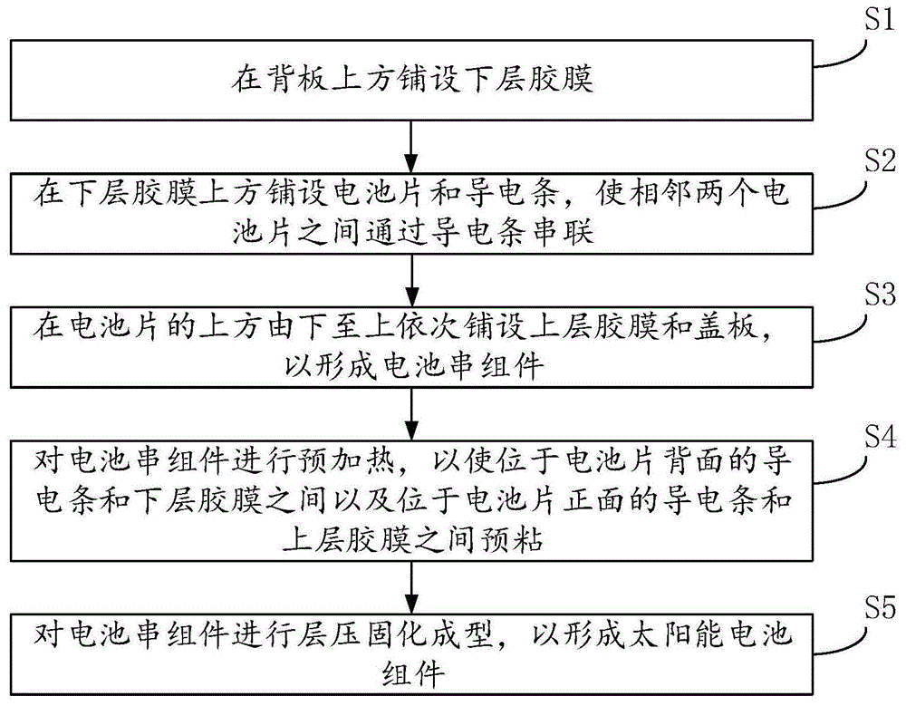
As shown in fig. 1, an embodiment of the present application provides a method for manufacturing a solar cell module, which includes the following steps:
step S1, laying the lower adhesive film 2 on the back plate 1.
The back plate 1 can be laid on the platform in advance, and then the lower adhesive film 2 is laid on the set area of the back plate 1.
Step S2, laying the battery pieces 3 and the conductive strips 4 above the lower-layer adhesive film 2, and connecting two adjacent battery pieces 3 in series through the conductive strips 4.
The number of the battery pieces 3 and the number of the conductive strips 4 can be multiple, and the battery pieces 3 and the conductive strips 4 can be alternately laid, so that the battery pieces 3 are sequentially connected in series from one end of the lower adhesive film 2 to the other end through the conductive strips 4.
And step S3, laying an upper-layer adhesive film 5 and a transparent cover plate 6 above the battery piece 3 from bottom to top in sequence to form a battery string assembly.
Step S4, preheating the battery string assembly to pre-bond the conductive strips 4 on one side of the battery piece 3 and the lower adhesive film 2 and the conductive strips 4 on the other side of the battery piece 3 and the upper adhesive film 5.
It should be noted that should preheat for low temperature heating, the temperature of this low temperature heating is far less than the temperature when laminating, and upper rubber membrane 5 and lower rubber membrane 2's material can include in EVA, POE, PET one or several kinds, when the film that contains materials such as EVA, POE, PET received the heating of certain degree, can take place the melting. In this embodiment, after the upper adhesive film 5 and the lower adhesive film 2 are preheated at a low temperature, the upper adhesive film 5 and the lower adhesive film 2 can be slightly melted, so that the conductive strips 4 on two sides of the battery piece 3 can be respectively bonded with the upper adhesive film 5 and the lower adhesive film 2, thereby realizing pre-fixing; meanwhile, the parts of the upper adhesive film 5 and the lower adhesive film 2, which are not adhered to the conductive strips 4, can be adhered to the battery piece 3, so that the pre-fixation between the upper adhesive film 5 and the battery piece 3 and the pre-fixation between the lower adhesive film 2 and the battery piece 3 are also realized.
Of course, the upper adhesive film 5 and the lower adhesive film 2 may be bonded to the back plate 1 and the transparent cover plate 6, respectively, after being melted. Therefore, before the battery string component is sent into the laminating equipment, the upper adhesive film 5 and the lower adhesive film 2 are slightly melted by preheating the battery string component at low temperature so as to slightly bond the battery piece 3, the conductive strip 4, the back plate 1 and the transparent cover plate 6, so that the whole battery string component has a relatively stable form before entering the laminating equipment.
And step S5, laminating, curing and molding the cell string assembly to form the solar cell assembly.
Compared with the prior art, the solar cell module manufacturing method provided by the embodiment adopts the conductive strips 4 to realize series connection of the cell pieces 3, and can realize pre-fixing of the conductive strips 4, the upper-layer adhesive film 5 and the lower-layer adhesive film 2 only by carrying out low-temperature preheating on the cell piece module.
Specifically, the heating temperature range for preheating the battery string assembly may be 70 to 80 ℃.
In the prior art, the temperature range for high-temperature welding the welding strip and the battery piece 3 is usually 200-400 ℃, and special high-temperature welding equipment is needed to realize the high-temperature welding. In the embodiment, high-temperature welding is not needed before the battery string component is sent into the laminating equipment, and the upper adhesive film 5 and the lower adhesive film 2 are slightly melted only through lower temperature, so that the conductive strip 4 is fixed through adhesive force, high-temperature welding is not needed, special high-temperature welding equipment is not needed, the cost is saved, and the forming process is simplified.
In addition, the preheating mode of this embodiment is simple, specifically can adopt the instrument to carry out contact preheating, also can adopt laser heating's mode, can also adopt the mode of platform heating, and the preferred mode that adopts platform heating in this embodiment, promptly, before laying lower floor's glued membrane 2 on backplate 1, can lay backplate 1 on preheating the platform to preheat this battery cluster subassembly through preheating the platform.
The preheating platform can preheat the battery string component within the temperature range of 70-80 ℃, and preferably, the preheating temperature is 75 ℃.
Specifically, in step S4, the method for preheating the battery string assembly may specifically include:
spot heating is performed at the locations of the cell string assembly having the conductive strips 4.
The conducting strip 4 is long strip, the conducting strip 4 is connected with two opposite electrodes on two adjacent battery pieces 3, the conducting strip 4 only covers part of the surface of the battery pieces 3, the area where the conducting strip 4 is located on the battery string component can be preheated by adopting a point heating mode, so that the heat can be concentrated in the area where the conducting strip 4 is located, the melting of the part, located at the area where the conducting strip 4 is located, of the upper-layer adhesive film 5 and the lower-layer adhesive film 2 is accelerated, and the preheating and bonding efficiency is improved.
Specifically, when adopting the platform of preheating to preheat the battery cluster subassembly, can have a plurality of heating point on the platform of preheating, when laying on the platform of preheating and forming the battery cluster subassembly, can align the heating point on the district and the platform of preheating of conducting strip 4 place to can realize the point heating to conducting strip 4 place region through preheating the platform.
Of course, a surface heating method, that is, preheating the surface of the entire battery string assembly, may be adopted, and this embodiment is not limited thereto.
As a specific implementation manner, the step of connecting two adjacent battery pieces 3 in series through the conductive strip 4 specifically includes:
step S21, connecting two adjacent battery slices 3 in series through a plurality of conductive strips 4 parallel to each other, as shown in fig. 5 and 7.
The two-side electrodes of the battery piece 3 can comprise a plurality of metal thin grid lines, and the conductive strip 4 can be vertically connected with the plurality of metal thin grid lines on the battery piece 3; and through setting up many conducting strips 4 that are parallel to each other, can promote the collection efficiency to electric current on the thin-grating line, promote the generated energy.
Step S22, a conductive strip 7 is used to connect with a plurality of conductive strips 4 parallel to each other.
The conductive strips 7 can be perpendicular to the conductive strips 4 to connect with a plurality of conductive strips 4 at the same time, so as to ensure stable connection of the plurality of conductive strips 4 and the battery piece 3.
In a specific embodiment, as shown in fig. 2, 4 and 5, the method comprises the steps of:
step S10, laying the lower adhesive film 2 on the back plate 1.
Step S20, the surfaces of the plurality of battery pieces 3 with the same polarity are uniformly laid on the lower adhesive film 2 at intervals.
In this embodiment, the back electrodes of the battery pieces 3 face one side of the lower adhesive film 2.
Step S30, after the conductive strip 4 is bent between two adjacent battery pieces 3, two ends of the conductive strip 4 are respectively connected in series with the surfaces of the two adjacent battery pieces 3 with opposite polarities.
As shown in fig. 4, a plurality of battery pieces 3 have a predetermined spacing distance therebetween, one end of each conductive strip 4 is connected to the back electrode of one battery piece 3, the other end of each conductive strip 4 needs to be connected to the front electrode of an adjacent battery piece 3, and the conductive strips 4 can be bent between two adjacent battery pieces 3.
When preheating the battery cluster subassembly, the one end that links to each other with 3 back electrodes of battery piece on the busbar 4 can bond with lower floor's glued membrane 2, and the one end that links to each other with 3 front electrodes of battery piece on the busbar 4 can bond with upper glued membrane 5 to the fixing to busbar 4 has been realized.
Step S40, bonding the conductive strip 7 to the conductive strip 4 at the position between two adjacent battery plates 3.
As shown in fig. 4 and 5, in order to connect the plurality of conductive strips 4 between the two battery pieces 3, a conductive strip 7 may be disposed between the two battery pieces 3 and connected to a bent portion of the conductive strip 4 between the two battery pieces 3. From this, through setting up electrically conductive thin strip 7, can link to each other with many conducting strips 4 simultaneously, guaranteed the stable connection of many conducting strips 4 and battery piece 3.
And step S50, laying an upper-layer adhesive film 5 and a transparent cover plate 6 above the battery piece 3 from bottom to top in sequence to form a battery string assembly.
Step S60, preheating the battery string assembly to pre-bond the conductive strips 4 on one side of the battery piece 3 and the lower adhesive film 2 and the conductive strips 4 on the other side of the battery piece 3 and the upper adhesive film 5.
And step S70, laminating, curing and molding the cell string assembly to form the solar cell assembly.
Therefore, in the embodiment, the conductive thin strips 7 are arranged, so that the connection stability of the conductive strips 4 and the battery pieces 3 between two adjacent battery pieces 3 can be realized, and meanwhile, the distortion of the positions between the two battery pieces 3 on the conductive strips 4 in all directions can be prevented through the constraint effect of the conductive thin strips 7, so that different stress changes are generated on the battery pieces 3, and the forming effect of the battery piece assembly and the service life of the battery pieces 3 are influenced.
In another specific embodiment, as shown in fig. 3, 6 and 7, the conductive strip 4 specifically includes an upper conductive strip 4 and a lower conductive strip 4; the method comprises the following steps:
step S100, laying a lower adhesive film layer 2 on the back plate 1.
Step S200, laying the lower conductive strip 4 on the lower adhesive film 2.
Step S300, the surfaces of the plurality of battery pieces 3 with different polarities are uniformly and alternately laid on the lower conductive strips 4.
When the battery pieces 3 are laid, the opposite polarities are arranged on the sides, facing the lower adhesive film 2, of the two adjacent battery pieces 3, so that the conductive strips 4 can be connected in series on the same side of the two adjacent battery pieces 3.
The back sheet 1 may be a transparent back sheet 1 with certain strength and weather resistance, such as a transparent glass back sheet 1, a transparent plastic back sheet 1, and the like, so that the front electrode on the side of the battery sheet 3 facing the back sheet 1 can receive light.
And S400, laying the upper conductive strips 4 on the cell 3.
It can be understood that the upper conductive strips 4 and the lower conductive strips 4 are distributed on two sides of the cell 3 in a staggered manner, so that the series connection of a plurality of cells 3 can be realized.
And S500, paving an upper-layer adhesive film 5 and a transparent cover plate 6 above the battery piece 3 from bottom to top in sequence to form a battery string assembly.
Step S600, preheating the battery string assembly to pre-bond the conductive strip 4 on one side of the battery piece 3 and the lower adhesive film 2 and the conductive strip 4 on the other side of the battery piece 3 and the upper adhesive film 5.
In this embodiment, when preheating the battery cluster subassembly, upper bus bar 4 can be fixed with 5 bonding of upper rubber membrane, and lower floor's bus bar 4 can be fixed with 2 bonding of lower floor's rubber membrane.
And S700, laminating, curing and molding the cell string assembly to form the solar cell assembly.
From this, through adopting upper bus bar 4 and lower floor's bus bar 4 to set up respectively and realize the series connection of each battery piece 3 in the both sides mode of battery piece 3, can need not to buckle bus bar 4, made things convenient for arranging of bus bar 4, and bus bar 4 fixed reliability in preheating, make the battery cluster subassembly have higher stability, promoted the solidification shaping effect of battery cluster subassembly in lamination equipment.
As a specific implementation manner, during the lamination and curing molding process of the battery string assembly, the bus bar 8 and the conductive strip 4 can be welded at the same time.
In the prior art, the welding strip is welded with the cell 3 to form the cell string, and the welding of the welding spot and the cell 3 needs to be completed before entering the laminating equipment, so after the solidified solar cell module is laminated, the bus bar 8 needs to be welded in the welding process. In the embodiment, the conductive strip 4 is adopted to replace the application of the existing solder strip, so that the conductive strip 4 and the bus bar 8 can be molded in the same process, and the preparation process of the solar cell module is simplified.
Wherein the bus bar 8 may be a low temperature weldable material to enable welding during lamination. In this embodiment, the bus bar 8 may be made of the same material as the bus bar 4, and specifically may be one of tin, lead, or bismuth.
It should be noted that when light irradiates on the conductive strip 4, light is generally refracted and reflected inside the conductive strip 4, and in order to make the light irradiate on the battery piece 3 after being refracted or reflected, in this embodiment, the cross section of the conductive strip 4 may be circular, trapezoidal, or triangular, and preferably, the cross section of the conductive strip 4 is trapezoidal.
The embodiment of the application also provides a solar cell module, and the solar cell module can be prepared by the preparation method of the solar cell module provided by any embodiment of the application.
The solar cell module comprises a back plate 1, a lower adhesive film 2, a plurality of cell pieces 3, an upper adhesive film 5 and a transparent cover plate 6 which are sequentially paved from bottom to top, wherein the two adjacent cell pieces 3 are connected in series through a plurality of conductive strips 4, and the plurality of conductive strips 4 are connected with each other through conductive thin strips 7.
It can be understood that the two-sided electrodes of the battery sheet 3 may include a plurality of metal thin grid lines, and the conductive strip 4 may be vertically connected to the plurality of metal thin grid lines on the battery sheet 3; wherein, through setting up many conducting strips 4 that are parallel to each other, can promote the collection efficiency to electric current on the thin-grating line, promote the generated energy. In addition, the conductive strips 7 can be perpendicular to the conductive strips 4 to connect with a plurality of conductive strips 4 at the same time, so that stable connection of the plurality of conductive strips 4 and the battery piece 3 is ensured.
The above description is only a preferred embodiment of the present application and is not intended to limit the present application, and various modifications and changes may be made by those skilled in the art. Any modification, equivalent replacement, improvement and the like made within the spirit and principle of the present application shall be included in the protection scope of the present application.