Background
It is common for the drive assembly to include a preferred operating window within which the performance of the drive assembly can be optimized. However, in practical scenarios, the drive assembly is generally not always able to operate in the preferred operating region due to environmental gravitational forces or resistance from the driving object.
Disclosure of Invention
The invention provides an adjusting mechanism, a driving device and machine equipment, which are used for solving the problem that the prior art cannot work in a better working area all the time.
In order to solve the technical problems, the invention adopts a technical scheme that: providing an adjustment mechanism comprising: the output shaft is used for being connected with the output end of the rotary driving piece, a cam piece is sleeved on the output shaft, the cam piece comprises an outer contour surface surrounding the output shaft, the outer contour surface at least comprises a first area and a second area in the circumferential direction, and the distance between the first area and the output shaft is larger than the distance between the second area and the output shaft; and the fixed shell comprises an elastic abutting part which is used for abutting against the outer contour surface, wherein when the elastic abutting part abuts against the first region, the elastic abutting part performs elastic energy storage under the pressure of the cam piece, and when the elastic abutting part abuts against the second region, the elastic abutting part releases the elastic energy storage to provide torque compensation for the output shaft.
According to an embodiment of the present invention, the elastic contact member contacts the outer contour surface in a direction perpendicular to an axis of the output shaft.
According to an embodiment of the present invention, the cam member includes an annular groove provided along a circumferential direction of the outer contour surface, the outer contour surface includes a groove bottom surface of the annular groove, and the elastic abutment member abuts against the groove bottom surface.
According to an embodiment of the present invention, the cam member includes a slide rail disposed along a circumferential direction of the outer contour surface, and a slider is disposed at an end of the elastic abutment member to cooperate with the slide rail such that the elastic abutment member is slidably disposed on the slide rail.
According to an embodiment of the present invention, the angle-distance curve of the outer contour surface with respect to the output shaft along the circumferential direction is a preset curve.
According to an embodiment of the present invention, the elastic abutment member includes an elastic member and an abutment member disposed at a first end of the elastic member near the cam member and abutting against the outer contour surface.
According to an embodiment of the present invention, the fixing housing includes an accommodating passage, the elastic member is located in the accommodating passage, and at least a portion of the abutting member is located in the accommodating passage.
According to an embodiment of the present invention, the elastic abutting member further includes an adjusting member, and the adjusting member is disposed at a second end of the elastic member away from the cam member, and is used for adjusting a distance between the second end and the output shaft.
According to an embodiment of the present invention, the accommodating channel is a through hole, and an internal thread is disposed at an end away from the cam member, the adjusting member is disposed with an external thread, and the adjusting member is fixed to the fixed housing by a screw-fit and is rotated by a screw to adjust a distance between the second end and the output shaft.
According to an embodiment of the present invention, the fixed housing is sleeved on the output shaft and is rotatably disposed relative to the output shaft, the adjusting mechanism further includes a bearing, an inner ring of the bearing is fixed to the output shaft, and an outer ring of the bearing is fixed to the fixed housing.
In order to solve the technical problems, the invention adopts a technical scheme that: there is provided a drive arrangement comprising a rotary drive member and an adjustment mechanism as in any of the embodiments above, the adjustment mechanism comprising: the output shaft is connected with the output end of the rotary driving piece, a cam piece is sleeved on the output shaft, the cam piece comprises an outer contour surface surrounding the output shaft, the outer contour surface at least comprises a first area and a second area in the circumferential direction, and the distance between the first area and the output shaft is larger than the distance between the second area and the output shaft; and the fixed shell comprises an elastic abutting part which is used for abutting against the outer contour surface, wherein when the elastic abutting part abuts against the first region, the elastic abutting part performs elastic energy storage under the pressure of the cam piece, and when the elastic abutting part abuts against the second region, the elastic abutting part releases the elastic energy storage to provide torque compensation for the output shaft.
According to an embodiment of the present invention, the driving device further comprises a speed reduction assembly connecting the output shaft and the output end of the rotary driving member, the speed reduction assembly comprising a sun gear, a plurality of planet gears and an internal gear; the sun gear is connected with the output end of the rotary driving piece, the plurality of planet gears are arranged around the sun gear and are all meshed with the sun gear, and the internal gear surrounds the plurality of planet gears and is meshed with the plurality of planet gears; wherein the output shaft is fixed to the plurality of planetary gears, and the fixed housing is fixed to the internal gear.
According to an embodiment of the present invention, the fixed housing is sleeved on the output shaft and is fixed to the seat of the rotary driving member.
In order to solve the technical problems, the invention adopts a technical scheme that: there is provided a machine arrangement, characterized in that it comprises a drive device according to any one of the preceding claims.
Has the advantages that: different from the prior art, the cam piece is arranged on the output shaft, the outer contour surface of the cam piece comprises a first area and a second area, the fixed shell comprising an elastic abutting piece is further arranged, when the elastic abutting piece abuts against the first area, the elastic abutting piece performs elastic energy storage under the pressure of the cam piece, and when the elastic abutting piece abuts against the second area, the elastic abutting piece releases the elastic energy storage to provide torque compensation for the output shaft. Namely, the compensation and adjustment of the output shaft can effectively keep the whole rotary driving piece to work in a better working interval.
Detailed Description
The technical solutions in the embodiments of the present invention will be clearly and completely described below with reference to the drawings in the embodiments of the present invention, and it is obvious that the described embodiments are only a part of the embodiments of the present invention, and not all of the embodiments. All other embodiments, which can be derived by a person skilled in the art from the embodiments given herein without making any creative effort, shall fall within the protection scope of the present invention.
In addition, if there is a description of "first", "second", etc. in an embodiment of the present invention, the description of "first", "second", etc. is for descriptive purposes only and is not to be construed as indicating or implying relative importance or implicitly indicating the number of technical features indicated. Thus, a feature defined as "first" or "second" may explicitly or implicitly include at least one such feature. In addition, technical solutions between various embodiments may be combined with each other, but must be realized by a person skilled in the art, and when the technical solutions are contradictory or cannot be realized, such a combination should not be considered to exist, and is not within the protection scope of the present invention.
Referring to fig. 1-10, the present invention provides an adjusting mechanism 10, wherein the adjusting mechanism 10 includes an output shaft 200 and a stationary housing 300. Alternatively, the adjustment mechanism 10 may be specifically adapted to cooperate with the rotary drive 100 to adjust output torque and power.
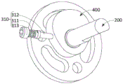
As shown in fig. 1, the output shaft 200 may be particularly connected to the output end of the rotary drive member 100, the output shaft 200 having a cam member 400 thereon, the cam member 400 including an outer contoured surface 410 about the output shaft 200, the outer contoured surface 410 including a plurality of regions in a circumferential direction, wherein at least two of the regions are spaced from the output shaft at different distances.
The rotary driving element 100 may be a rotary motor, such as a rotor motor, and the like, which is not limited herein.
As shown in fig. 7, the outer contour surface 410 may include a first region and a second region in the circumferential direction, wherein the first region is spaced a greater distance from the output shaft 200 than the second region is spaced from the output shaft 200.
As shown in fig. 2 and 3, the fixed housing 300 includes an elastic abutment member 310, the elastic abutment member 310 is configured to abut against the outer contour surface 410, wherein when the elastic abutment member 310 abuts against the first region, the elastic abutment member 310 performs elastic energy storage under the pressure of the cam member 400, and when the elastic abutment member 310 abuts against the second region, the elastic abutment member 310 releases the elastic energy storage to provide torque compensation for the output shaft 200.
In a specific scenario, since the distances between the outer contour surface 410 and the output shaft 200 are all different in the circumferential direction, when the rotational driving element 100 drives the output shaft 200 and further drives the cam element 400 to rotate, the abutting degrees of the outer contour surface 410 and the elastic abutting element 310 are all different, optionally, since the first region is far from the output shaft 200, the abutting degree of the first region to the elastic abutting element 310 is strong, that is, corresponding pressure can be applied to the elastic abutting element 310, so that the elastic abutting element 310 starts to perform elastic energy storage, and since the second region is near to the output shaft 200, the abutting degree of the second region to the elastic abutting element 310 is weak, and then the elastic abutting element 310 can release the corresponding elastic energy storage to provide torque compensation for the output shaft 200.
Optionally, when the elastic abutting member 310 is elastically charged in the first region, the output shaft 200 may weaken a certain torque, and when the elastic abutting member 310 is in the second region, the output shaft 200 may be compensated for the torque, so as to overcome the influence caused by the environment, and thus keep the preferred working region of the entire adjusting mechanism 10.
For example, in a particular scenario, the adjustment mechanism 10 may be applied to a machine device, which may be in particular an exoskeleton robot, to power joints. Due to the influence of gravity and the degree of flexion of the joints, e.g. when the user wears the exoskeleton robot, for example, during walking, the assistance force required to be provided by wearing the exoskeleton robot is different, i.e. the target power required to be output by the adjustment mechanism 10 is different. In the case of a low target power requirement, the power output by the rotary drive 100 is greater than the target power, i.e. it is partially spilled, so that the excess energy can be stored elastically in the elastic abutment 310 by the cam element 400. In case the target power is high, the power output by the rotary driving member 100 is relatively low, i.e. compensation power is needed, so the elastic abutment member 310 can release the elastic energy storage and provide it to the output shaft 200 through the cam member 400.
In another scenario, if a user wears the exoskeleton robot to move a heavy object, when the heavy object is placed, the output shaft 200 can be driven to rotate under the action of gravity and further the elastic abutting part 310 can be subjected to elastic energy storage, and when the heavy object is moved, the elastic abutting part 310 can release the elastic energy storage and compensate the torque of the output shaft 200.
In a particular embodiment, the angle-distance curve of the outer contour surface 410 in the circumferential direction with respect to the output shaft 200 may be a predetermined curve. The preset curve may be a rectangular coordinate system, with the angle being the X-axis and the distance being the Y-axis. That is, in an alternative embodiment, the outer contour surface 410 is divided into 360 degrees, and a reference angle may be preset as 0 degrees (360 °), and a corresponding distance may be provided at each angle, with the rotation direction being the positive direction. This preset curve is generated in particular from the output power information of the regulating organ 10 and the required output power information of the required application scenario.
In the above embodiment, by providing the cam member 400 on the output shaft 200, and the outer contour surface 410 of the cam member 400 includes the first region and the second region, and further by providing the fixed housing 300 including the elastic abutment member 310, when the elastic abutment member 310 abuts against the first region, the elastic abutment member 310 performs elastic energy storage under the pressure of the cam member 400, and when the elastic abutment member 310 abuts against the second region, the elastic abutment member 310 releases the elastic energy storage to provide torque compensation for the output shaft 200. That is, by compensating and adjusting the output shaft 200, the whole adjusting mechanism 10 can be effectively kept to work in a preferred working range.
In an alternative embodiment, the outer contour surface 410 is a continuous curved surface in the circumferential direction. And the outer contour surface 410 may specifically include a plurality of regions in the circumferential direction, including a first region and a second region, with different regions being spaced from the output shaft at different distances in alternative embodiments. I.e., cam member 400 is an irregular annular body structure.
In an alternative embodiment, there may also be a region of the plurality of regions that has a short distance from the output shaft 200, such that the resilient abutment 310 cannot directly contact the region.
In an alternative scenario, the plurality of regions are regions having a longer circumferential length, and each adjacent region is a different distance from the output shaft 200. Alternatively, the distance from the output shaft 200 is different between each region.
In another alternative scenario, the plurality of regions are regions that may also have a shorter circumferential length, i.e. each region may be a line parallel to the axis of the output shaft 200, and the plurality of regions are at progressively increasing distances from the output shaft 200 in the circumferential direction.
In an alternative embodiment, the resilient abutment 310 may abut the outer contour surface 410 in a direction perpendicular to the axis of the output shaft 200. Thereby achieving the best energy storage or release energy storage effect. It should be noted that the perpendicular is an angle that can satisfy a certain angle error, such as an angle that is technically unavoidable.
In an alternative embodiment, the plane in which the resilient abutment 310 and the outer contour surface 410 abut each other is parallel.
In an alternative embodiment, the outer contour surface 410 is parallel to the axis of the output shaft 200.
In an alternative embodiment, the elastic abutment member 310 may also abut against the outer contour surface 410 at an angle of 45 ° to 90 ° with respect to the axis of the output shaft 200, which is not limited herein.
In an alternative embodiment, the elastic abutment member 310 may be a plurality, which is not limited herein.
In an alternative embodiment, the cam member 400 includes an annular groove (not shown) disposed circumferentially around the outer contour surface 410, the outer contour surface 410 further includes a groove bottom surface of the annular groove, and the resilient abutment member 310 abuts against the groove bottom surface. That is, the cam member 400 may further include an annular groove, and the abutting portion of the elastic abutting member 310 and the cam member 400 may be located in the annular groove, and the length of the annular groove in the axial direction of the output shaft 200 is greater than the predetermined length of the elastic abutting member 310 in the axial direction of the output shaft 200, so that the displacement of the elastic abutting member 310 in the axial direction of the output shaft 200 may be limited, thereby improving the stability of the whole structure.
In an alternative embodiment, the cam member 400 may further comprise a slide rail (not shown) disposed along the circumference of the outer contour surface 410, and the end of the resilient abutment member 310 is provided with a slider block to engage with the slide rail such that the resilient abutment member 310 is slidably disposed on the slide rail and thereby abuts against the outer contour surface 410.
Alternatively, the sliding rail may be disposed in the annular groove, which is not limited herein.
As shown in fig. 3 and 8, the elastic abutment member 310 includes an elastic member 311 and an abutment member 312, and the abutment member 312 may be disposed at a first end of the elastic member 311 near the cam member 400 and abuts against the outer contour surface 410. Alternatively, the abutment member 312 and the first end of the elastic member 311 may be in a simple abutting relationship without being fixedly connected.
In an alternative embodiment, the elastic element 311 may be a compression spring, and the abutting element 312 may be a thimble.
As shown in fig. 3 and 4, the fixing housing 300 may further include an accommodating channel 320, the elastic member 311 is located in the accommodating channel 320, and at least a portion of the abutting member 312 is located in the accommodating channel 320.
That is, alternatively, the abutting piece 312 may be moved along the length direction of the accommodating channel 320, and when the output shaft 200 rotates the cam piece 400, and when the first region abuts against the abutting piece 312, the cam piece 400 provides pressure to the abutting piece 312 to move the abutting piece 312 towards the elastic piece 311, so that the elastic piece 311 compresses and starts elastic energy storage. When the two regions abut against the abutting member 312, the elastic member 311 releases the elastic energy storage and the abutting member 312 provides a certain compensation torque to the cam member 400. And by providing the receiving channel 420, the stability of the entire elastic member 311 and the abutment member 312 is ensured.
As shown in fig. 3, the elastic abutting member 310 further includes an adjusting member 313, and the adjusting member 313 is disposed at a second end of the elastic member 311 away from the cam member 400 for adjusting a distance between the second end and the output shaft 200.
In the above embodiment, by providing the adjusting member 313 for adjusting the distance between the second end of the elastic member 311 and the output shaft 200, the elastic force of the elastic member 311, i.e. the energy storage degree of the whole elastic abutting member 310, can be adjusted, thereby changing the torque adjusting amount and the compensation amount of the output shaft 200.
Specifically, the receiving channel 320 may be a through hole, an internal thread is disposed at one end away from the cam member 400, an external thread is disposed on the adjusting member 313, the adjusting member 313 may be fixed on the fixed housing 300 by the threaded engagement of the external thread and the internal thread of the receiving channel 320, and the distance between the second end and the output shaft 200 may be adjusted by the threaded rotation of the adjusting member 313.
Alternatively, by providing the adjusting element 313 with an external thread that is screwed into an internal thread of the receiving channel 320, on the one hand, the entire adjusting mechanism 10 can be disassembled without having to directly change the amount of torque adjustment and compensation of the output shaft 200 by twisting the adjusting element 313. On the other hand, because the elastic member 311 is not connected with the abutting member 312, the fixing with the fixed housing 300 can be released by loosening the adjusting member 313, so that the elastic member 311 can be replaced quickly and conveniently, not only the elastic member 311 causing elastic fatigue after long-term use can be replaced, but also the elastic member 311 with different specifications can be replaced according to requirements.
As shown in fig. 2 and fig. 3, the fixed housing 300 is sleeved on the output shaft 200 and is disposed to rotate relative to the output shaft 200, and optionally, the adjusting mechanism 10 further includes a bearing 500, an inner ring 510 of the bearing 500 is fixed to the output shaft 200, and an outer ring 520 of the bearing 500 is fixed to the fixed housing 300.
In a specific scenario, the adjusting mechanism 10 of the present application may be a modular structure, and may include multiple specifications to adapt to different rotary driving members 100, for example, the rotary driving member 100 is a commercially available HT3510 motor, and the adjusting mechanism 10 of the relevant corresponding specification may be provided for the motor to adapt to the motor, so as to adjust the output torque and power of the HT3510 motor. Similarly, different adaptations of the adjustment mechanism 10 may be provided for different rotary drives 100 to ensure that the adjustment mechanism 10 can be mated with the rotary drive 100. Therefore, flexible assembly can be realized, and the output power and the torque of the same rotary driving member 100 matched with the adjusting mechanisms 10 with different specifications are different, thereby maximizing the flexibility.
The present application also provides a drive arrangement comprising a rotary drive member 100 and an adjustment mechanism 10 as in any of the embodiments described above.
The output shaft 200 may be particularly adapted to be coupled to an output end of a rotary drive member 100, the output shaft 200 having a cam member 400, the cam member 400 including an outer contoured surface 410 about the output shaft 200, the outer contoured surface 410 including a plurality of regions in a circumferential direction, wherein at least two of the regions are spaced from the output shaft by different distances.
As shown in fig. 7, the outer contour surface 410 may include a first region and a second region in the circumferential direction, wherein the first region is spaced a greater distance from the output shaft 200 than the second region is spaced from the output shaft 200.
As shown in fig. 2 and 3, the fixed housing 300 includes an elastic abutment member 310, the elastic abutment member 310 is configured to abut against the outer contour surface 410, wherein when the elastic abutment member 310 abuts against the first region, the elastic abutment member 310 performs elastic energy storage under the pressure of the cam member 400, and when the elastic abutment member 310 abuts against the second region, the elastic abutment member 310 releases the elastic energy storage to provide torque compensation for the output shaft 200.
As shown in fig. 9 and 10, the driving apparatus further includes a reduction assembly 600 connecting the output shaft 200 with the output end of the rotary driving member 100, the reduction assembly 600 including a sun gear 610, a plurality of planet gears 620, and an inner gear 630; the sun gear 610 is connected to an output end of the rotary driving member 100, the plurality of planetary gears 620 are disposed around the sun gear 610 and are all engaged with the sun gear 610, and the internal gear 630 surrounds the plurality of planetary gears 620 and is engaged with the plurality of planetary gears 620. And further, the output shaft 200 is fixed with the plurality of planetary gears 620, and the stationary housing 300 is fixed with the inner gear 630.
Optionally, the number of the planetary gears 620 may be 3, and by providing the speed reduction assembly 600, the rotation speed of the output shaft 200 relative to the output end of the rotary driving element 100 may be effectively adjusted, and the output torque of the output shaft 200 may be increased.
In an alternative embodiment, the fixed housing 300 is disposed on the output shaft 200 and fixed to the seat of the rotary driving element 100.
In an alternative embodiment, the fixed housing 300 is disposed on the output shaft 200 and is rotatably disposed relative to the rotary driving element 100.
The present invention also provides a machine apparatus comprising the adjustment mechanism 10 of any of the embodiments described above.
Optionally, the machine device may be an exoskeleton robot, a quadruped robot, or other machine devices that may be affected by environmental factors such as a gravitational field, which is not limited herein.
In other embodiments, the machine device may also be a prosthetic limb, such as a machine device requiring periodic motion, such as walking or assisted walking, for example, a lower limb prosthesis or an upper limb prosthesis.
In summary, the adjusting mechanism, the driving device and the machine tool provided by the present invention are configured such that the cam member 400 is disposed on the output shaft 200, the outer contour surface 410 of the cam member 400 includes a first region and a second region, and further the fixed housing 300 including the elastic abutting member 310 is disposed, when the elastic abutting member 310 abuts against the first region, the elastic abutting member 310 performs elastic energy storage under the pressure of the cam member 400, and when the elastic abutting member 310 abuts against the second region, the elastic abutting member 310 releases the elastic energy storage to provide torque compensation for the output shaft 200. Namely, the compensation and adjustment of the output shaft 200 can effectively keep the whole driving device working in a better working range. And whole compact structure and simple, and can carry out convenient regulation and replacement etc. to elasticity butt piece 310, can carry out the quick change to the regulating variable and the compensation volume of output shaft 200 based on concrete application scene.
The above description is only an embodiment of the present invention, and not intended to limit the scope of the present invention, and all equivalent results or equivalent flow transformations performed by the present specification and drawings, or directly or indirectly applied to other related technical fields, are included in the scope of the present invention.