Detailed Description
(embodiment mode 1)
An embodiment of a lithium-ion secondary battery and a method for manufacturing the same will be described with reference to fig. 1. The lithium ion secondary battery 1 includes a cell 11, and the cell 11 includes a 1 st electrode 2, a separator 3 laminated on the 1 st electrode 2, and a 2 nd electrode 4 laminated on the separator 3. The 1 st electrode 2 comprises a porous body 21 having a large number of pores 211 and an active material 22 held in the pores 211, wherein the porous body 21 contains a LLZ-based solid electrolyte of 1 or 2 or more kinds of Lanthanum Lithium Zirconate (LLZ) and lanthanum lithium zirconate doped with atoms other than Li atoms, La atoms, and Zr atoms. The separator 3 contains 1 or 2 or more kinds of LLZ-based solid electrolyte of LLZ and lanthanum lithium zirconate doped with atoms other than Li atoms, La atoms, and Zr atoms, and 1 or 2 or more kinds of B atoms, P atoms, and Si atoms. The relative density of the separator 3 is 80% or more.
The lithium-ion secondary battery 1 may have one cell 11, or may have a plurality of cells 11. For example, the lithium-ion secondary battery 1 of the present embodiment has one cell 11. The current collectors 12 are laminated on the surfaces of the 1 st electrode 2 and the 2 nd electrode 4 in the unit cell 11, respectively. By adding or connecting a power generation device to these collectors 12, the lithium ion secondary battery 1 can be charged and discharged. As the current collector 12, for example, a conductor such as a metal foil or a metal plate, a composite material in which conductive powder such as carbon or conductive oxide is dispersed in an insulator such as glass, or the like can be used.
Although not shown in the drawings, when the lithium-ion secondary battery 1 has a plurality of cells 11, the plurality of cells 11 can be electrically connected via the current collectors 12 by alternately overlapping the current collectors 12 and the cells 11. For example, the current collector 12 is overlapped with the cells 11 by contacting one surface of the current collector 12 with the 1 st electrode 2 and contacting the other surface with the 2 nd electrode 4, whereby a plurality of cells 11 can be connected in series. Further, the current collector 12 is sandwiched between the electrodes 2 and 4 of the same kind, and the current collector 12 and the cell 11 are stacked, whereby the plurality of cells 11 can be connected in parallel.
The 1 st electrode 2 may be a positive electrode or a negative electrode. The 1 st electrode 2 of the present embodiment is specifically a positive electrode.
The shape of the 1 st electrode 2 may be in various forms. For example, although not shown in the drawings, the 1 st electrode 2 of the present embodiment has a rectangular plate shape formed of the porous body 21.
The porous body 21 contains 1 or 2 or more kinds of LLZ-based solid electrolyte selected from the group consisting of LLZ and lanthanum lithium zirconate doped with atoms other than Li atoms, La atoms, and Zr atoms. That is, the porous body 21 may be composed of an LLZ-based solid electrolyte, or may contain an LLZ-based solid electrolyte and a substance other than the LLZ-based solid electrolyte.
For example, the porous body 21 may further contain 1 or 2 or more of B atoms, P atoms, and Si atoms. That is, in the process of manufacturing the lithium-ion secondary battery 1, a sintering aid containing these atoms may be added to the porous body 21. In this case, the heating temperature at the time of sintering the porous body 21 can be further reduced, and the amount of energy consumed in the manufacturing process of the lithium-ion secondary battery 1 can be further reduced.
In the case where the sintering aid is also added to the porous body 21 in the production process of the lithium ion secondary battery 1, the total content of B atoms, P atoms, and Si atoms in the porous body 21 is preferably smaller than the total content of B atoms, P atoms, and Si atoms in the separator 3. At this time, crystal growth of the LLZ-based solid electrolyte in the separator 3 can be promoted, and excessive crystal growth of the LLZ-based solid electrolyte in the porous body 21 can be more reliably suppressed. As a result, the increase in the relative density of the porous body 21 can be more effectively suppressed, and the capacity of the lithium-ion secondary battery 1 can be further increased.
The porous body 21 has pores 211. The active material 22 is held in the pores 211 of the porous body 21. The pores 211 may hold a conductive auxiliary agent, a solid electrolyte different from the LLZ-based solid electrolyte, a liquid electrolyte, and the like in addition to the active material 22.
For example, as shown in fig. 1, the pores 211 of the porous body 21 may have a continuous pore structure. The relative density of the porous body 21, that is, the ratio of the apparent density of the entire porous body 21 including the pores 211 to the density of the portion other than the pores 211 in the porous body 21, may be 60% or less, for example. From the viewpoint of maintaining the shape of the porous body 21, the relative density of the porous body 21 may be, for example, 30% or more.
The relative density of the porous body 21 is a value calculated based on a three-dimensional reconstructed image obtained by a FIB/SEM (i.e., focused ion beam/scanning electron microscope) tomography method. More specifically, the processing of the sample by the FIB device and the observation of the processed surface by the SEM are repeated to obtain a plurality of SEM images. These SEM images were reconstructed by image analysis software, thereby obtaining a three-dimensional reconstructed image of the sample. Then, binarization processing is performed on the obtained three-dimensional reconstructed image so that the boundary between the porous body 21 and the other portions is not broken. The ratio of the total volume of the LLZ-based solid electrolyte and the volume of the sintering aid calculated from the binary image obtained above to the apparent volume of the porous body 21 was defined as the relative density of the porous body 21.
The active material 22 may be appropriately selected according to the polarity of the 1 st electrode 2. For example, when the 1 st electrode 2 is a positive electrode, a sulfur-based active material containing a sulfur atom or an oxide-based active material composed of an oxide can be used as the active material 22 of the 1 st electrode 2. As the sulfur-based active material, specifically, a simple substance of sulfur, lithium sulfide (Li) can be used2S), sulfur doped with lithium, and the like. As the oxide-based active material, specifically, lithium cobaltate (LiCoO) can be used2)、LiNi1/3Mn1/3Co1/3O2Lithium manganate (LiMnO)2) Lithium iron phosphate (LiFePO)4) And the like.
When the 1 st electrode 2 is a positive electrode, the active material 22 preferably contains a sulfur atom. In this case, the capacity of the lithium-ion secondary battery 1 can be further increased. The active material 22 of the present embodiment is specifically a sulfur monomer.
When the 1 st electrode 2 is a negative electrode, metallic lithium, carbon, or Li can be used as the active material 22 of the 1 st electrode 24Ti5O12And the like.
As shown in fig. 1, the separator 3 is formed integrally with the porous body 21 of the 1 st electrode 2. The relative density of the separator 3 is 80% or more. Thus, the separator 3 can suppress a short circuit between the 1 st electrode 2 and the 2 nd electrode 4. From the viewpoint of more reliably suppressing the short circuit between the 1 st electrode 2 and the 2 nd electrode 4, the relative density of the separator 3 is preferably 90% or more, and more preferably 95% or more. In addition, the relative density of the separator 3 can be calculated as in the case of calculating the relative density of the porous body 21.
The separator 3 contains 1 or 2 or more kinds of LLZ-based solid electrolyte of LLZ and LLZ doped with atoms other than Li atoms, La atoms, and Zr atoms, and 1 or 2 or more kinds of B atoms, P atoms, and Si atoms. That is, in the production process of the lithium-ion secondary battery 1, a sintering aid containing these atoms may be added to the separator 3. The sintering aid containing these atoms melts earlier than the LLZ-based solid electrolyte when sintering the porous body 21 and the separator 3 in the manufacturing process of the lithium ion secondary battery 1. Further, the crystal growth of the LLZ-based solid electrolyte can be promoted by bringing the molten sintering aid into contact with the LLZ-based solid electrolyte.
Therefore, by adding the sintering aid to the separator 3 in the manufacturing process of the lithium ion secondary battery 1, the crystal growth rate of the LLZ-based solid electrolyte in the separator 3 during sintering can be increased. As a result, excessive progress of crystal growth of the LLZ-based solid electrolyte in the porous body 21 can be suppressed, and crystal growth of the LLZ-based solid electrolyte in the separator 3 can be promoted.
From the viewpoint of enhancing the effect of promoting crystal growth of the LLZ-based solid electrolyte, it is preferable to use a sintering aid having a low melting point. In addition, the melting point of the sintering aid tends to be the lowest among the sintering aids containing B atoms, and the melting point of the sintering aid containing P atoms and the melting point of the sintering aid containing Si atoms tend to be higher in this order. Therefore, from the viewpoint of promoting crystal growth of the LLZ-based solid electrolyte in the separator 3, it is most preferable that the separator 3 contains B atoms, and it is next preferable that the separator contains P atoms.
In addition, when the sintering aid is added to the porous body 21 also in the manufacturing process of the lithium ion secondary battery 1, the melting point of the sintering aid used in the porous body 21 is preferably higher than the melting point of the sintering aid used in the separator 3. That is, when the separator 3 contains B atoms, 1 or 2 of P atoms and Si atoms are preferably contained in the porous body 21. When the separator 3 contains P atoms, the porous body 21 preferably contains Si atoms.
By setting the melting point of the sintering aid in the porous body 21 higher than the melting point of the sintering aid in the separator 3 in this way, crystal growth of the separator 3 can be promoted, and excessive crystal growth of the porous body 21 can be more reliably suppressed. As a result, the increase in the relative density of the porous body 21 can be more effectively suppressed, and the capacity of the lithium-ion secondary battery 1 can be further increased.
The content of B atoms, P atoms, and Si atoms in the separator 3 is preferably 12 mol% to 65 mol% with respect to La (lanthanum) atoms in the separator 3. In this case, the lithium ion conductivity can be improved by sufficiently securing the amount of the LLZ-based solid electrolyte in the separator 3, and the sintering promoting effect by the sintering aid can be obtained.
The LLZ-based solid electrolyte contained in the separator 3 may be the same as or different from the LLZ-based solid electrolyte of the porous body 21. It is preferable that the average crystal grain diameter of the LLZ-based solid electrolyte in the separator 3 is larger than the average crystal grain diameter of the LLZ-based solid electrolyte in the porous body 21. At this time, the relative density of the separator 3 can be further increased, and the relative density of the porous body 21 can be further decreased. As a result, the lithium ion conductivity can be further improved, and the internal resistance can be further reduced. In addition, the amount of lithium storable in the pores 211 can be increased to further increase the capacity of the lithium-ion secondary battery 1.
The average crystal grain diameter of the LLZ-based solid electrolyte in the porous body 21 and the separator 3 can be measured by the following method. That is, first, the lithium-ion secondary battery 1 is cut in the stacking direction of the porous body 21 and the separator 3 so that the cross section is exposed. The cross section was observed with a scanning electron microscope to obtain an SEM image. Then, the maximum diameter of the crystal of the plurality of LLZ-based solid electrolytes present in the SEM image was measured. The average of these maximum diameters was defined as the average crystal grain diameter of the LLZ-based solid electrolyte. The number of crystals of the LLZ-based solid electrolyte used for calculating the average crystal grain size is not particularly limited, but a larger number of crystals can be used for calculating the average crystal grain size to obtain a more accurate value. From the above viewpoint, the number of crystals of the LLZ-based solid electrolyte used for calculating the average crystal grain diameter is preferably 10 or more, and more preferably 20 or more.
The 2 nd electrode 4 is laminated on the surface of the separator 3 opposite to the surface on which the 1 st electrode 2 is provided. The 2 nd electrode 4 has a different polarity from the 1 st electrode 2. That is, when the 1 st electrode 2 is configured as a positive electrode, the 2 nd electrode 4 is configured as a negative electrode. When the 1 st electrode 2 is configured as a negative electrode, the 2 nd electrode 4 is configured as a positive electrode.
The structure of the 2 nd electrode 4 is not particularly limited. For example, the 2 nd electrode 4 may be constituted only of an active material different from the active material 22 of the 1 st electrode 2, or may be constituted so as to hold an active material in the pores of the porous body as in the 1 st electrode 2.
The active material of the 2 nd electrode 4 can be appropriately selected according to the polarity of the 2 nd electrode 4. For example, the 2 nd electrode 4 of the present embodiment is a lithium plate made of metal lithium as an active material.
Next, a method for manufacturing the lithium-ion secondary battery 1 of the present embodiment will be described. The method for manufacturing the lithium-ion secondary battery 1 of the present embodiment includes: a lamination step of producing a laminate by laminating the 1 st layer to be the porous body 21 after sintering and the 2 nd layer to be the separator 3 after sintering; and a co-sintering step of sintering the laminate at a temperature of 700 to 1050 ℃ to integrally form the porous body 21 and the separator 3.
In the lamination step, various methods can be used to form the 1 st and 2 nd layers. For example, in one embodiment of the lamination process, a green sheet as the 1 st layer can be produced by preparing a mixture for a separator containing an LLZ-based solid electrolyte, a solvent, a sintering aid, and a binder, and then molding the mixture for a separator into a sheet shape. As the LLZ-based solid electrolyte used in the mixture for a separator, for example, a solid electrolyte obtained by pulverizing crystals of the solid electrolyte into powder can be used.
The cumulative 50% particle diameter (i.e., d50) on a volume basis of the LLZ-based solid electrolyte used in the mixture for separators is preferably 1.0 μm or less. At this time, the surface area of the LLZ-based solid electrolyte in the 1 st layer is further increased, and therefore, the crystal growth of the LLZ-based solid electrolyte during sintering can be further promoted. As a result, the relative density of the separator 3 can be further increased. In this case, the thickness of the 1 st layer can be easily reduced while suppressing the formation of defects such as pinholes in the 1 st layer. As a result, the thickness of the obtained separator 3 can be further reduced.
As the sintering aid, an inorganic compound containing 1 or 2 of B atoms, P atoms, and Si atoms, or the like can be used. From the viewpoint of further increasing the capacity of the lithium ion secondary battery 1, it is preferable to use Li as the sintering aid3BO3、Li6B4O9、Li4B2O5、LiBO2、B2O3、Li3PO4、Li4SiO4And Li2SiO31 or 2 or more.
Alternatively, a green sheet as the 2 nd layer can be prepared by preparing an electrode mixture containing an LLZ-based solid electrolyte, a solvent, a pore-forming material, and a binder, and then forming the electrode mixture into a sheet shape. As the pore-forming material, for example, acrylic resin powder or the like can be used. The electrode mixture may contain the sintering aid in addition to the LLZ-based solid electrolyte, the solvent, the pore-forming material, and the binder.
The green sheet of the porous body 21 thus obtained and the green sheet of the separator 3 are stacked and then integrated by a method such as thermocompression bonding, thereby obtaining a laminate.
In another embodiment of the lamination step, a powder mixture containing an LLZ-based solid electrolyte and a pore-forming material is compression-molded to produce a powder compact as the 1 st layer. By disposing a mixed powder containing an LLZ-based solid electrolyte and a sintering aid on the green compact and compression-molding the mixed powder, a green compact as a 2 nd layer can be formed on the 1 st layer to obtain a laminate.
In the co-sintering step, the laminate obtained in the lamination step is heated at a temperature of 700 ℃ or higher and less than 1050 ℃. When the heating temperature in the co-sintering step is within the above-mentioned specific range, the sintering aid is melted before the LLZ-based solid electrolyte to produce a melt of the sintering aid. The crystal growth of the LLZ-based solid electrolyte can be promoted by bringing the molten sintering aid into contact with the LLZ-based solid electrolyte. Therefore, by heating at the above-described temperature in the specific range, crystal growth of the LLZ-based solid electrolyte in the separator 3 can be promoted.
On the other hand, the precursor of the porous body 21 contains a pore-forming material. Therefore, in the co-sintering step, the pore former disappears first, and the fine pores 211 are formed. Thereafter, the LLZ-based solid electrolyte in the precursor of the porous body 21 starts crystal growth. In this case, the precursor of the porous body 21 does not contain a sintering aid, or is configured to have a lower sintering aid effect than the precursor of the separator 3. Therefore, the crystal growth rate of the LLZ-based solid electrolyte in the porous body 21 is slower than that of the LLZ-based solid electrolyte in the separator 3.
Therefore, in the co-sintering step, the LLZ solid electrolyte in the separator 3 can be sufficiently crystal-grown while suppressing excessive crystal growth of the LLZ solid electrolyte in the porous body 21 by heating the laminate at the temperature in the above-described specific range.
The heating temperature in the co-sintering step is preferably 900 ℃ or higher. In this case, the crystal growth rate of the LLZ-based solid electrolyte can be further increased in both the porous body 21 and the separator 3 while maintaining the magnitude relationship of the crystal growth rate.
On the other hand, if the heating temperature in the co-sintering step is too high, crystal growth tends to occur in a state where the LLZ-based solid electrolyte is alone. Therefore, crystal growth of the LLZ-based solid electrolyte in the porous body 21 excessively proceeds, and there is a possibility that the capacity of the lithium-ion secondary battery 1 is reduced. The above problem can be avoided by making the heating temperature in the co-sintering process less than 1050 ℃. From the same viewpoint, the heating temperature in the co-sintering step is preferably 1000 ℃.
With the above, the porous body 21 and the separator 3 can be integrally formed. The lithium-ion secondary battery 1 can be formed by holding the active material 22 in the pores 211 of the porous body 21 thus obtained and disposing the 2 nd electrode 4 on the back surface of the separator 3 on the side having the porous body 21.
Various methods can be employed for holding the active material 22 in the pores 211 of the porous body 21. For example, the active material 22 itself may be filled in the pores 211 to hold the active material 22 in the pores 211. For example, the precursor of the active material 22 may be filled in the pores 211 and then converted into the active material 22 by a treatment such as heating.
(embodiment mode 2)
This embodiment shows another embodiment of the 2 nd electrode. The same reference numerals as those used in the above-described embodiment among the reference numerals used in the present embodiment and the following description denote the same components and the like as those used in the above-described embodiment unless otherwise specified. In the lithium-ion secondary battery 102 of the present embodiment, the porous body 21 is referred to as the 1 st porous body 21, and the active material 22 of the 1 st electrode 2 is referred to as the 1 st active material 22. The 1 st electrode 2 of this embodiment has the same configuration as that of embodiment 1, except that the 1 st active material 22 is lithium-doped sulfur. The spacer 3 of the present embodiment has the same configuration as that of embodiment 1.
As shown in fig. 2, the 2 nd electrode 402 of the present embodiment includes a 2 nd porous body 41 containing an LLZ-based solid electrolyte and having pores 411, and a 2 nd active material 42 held in the pores 411.
The specific configuration of the 2 nd porous body 41 in the 2 nd electrode 402 is the same as that of the 1 st porous body 21 of the 1 st electrode 2. That is, the 2 nd porous body 41 may be composed of an LLZ-based solid electrolyte, and may contain a substance other than the LLZ-based solid electrolyte and the LLZ-based solid electrolyte. The LLZ-based solid electrolyte contained in the 2 nd porous body 41 may be the same as or different from the LLZ-based solid electrolyte contained in the 1 st porous body 21 or the separator 3.
The 2 nd porous body 41 may further contain 1 or 2 or more of B atoms, P atoms, and Si atoms. That is, in the process of manufacturing the lithium ion secondary battery 1, a sintering aid containing these atoms may be added to the 2 nd porous body 41. In this case, the heating temperature at the time of sintering the 2 nd porous body 41 can be further reduced, and the amount of energy consumed in the manufacturing process of the lithium ion secondary battery 102 can be further reduced.
When the sintering aid is added to the 2 nd porous body 41 also in the production process of the lithium ion secondary battery 1, the total content of the B atoms, P atoms, and Si atoms in the 2 nd porous body 41 is preferably smaller than the total content of the B atoms, P atoms, and Si atoms in the separator 3. In this case, crystal growth of the LLZ-based solid electrolyte in the separator 3 can be promoted, and excessive crystal growth of the LLZ-based solid electrolyte in the 2 nd porous body 41 can be more reliably suppressed. As a result, the increase in the relative density of the 2 nd porous body 41 can be more effectively suppressed, and the capacity of the lithium-ion secondary battery 1 can be further increased.
From the same viewpoint, it is preferable that the melting point of the sintering aid used in the 2 nd porous body 41 is higher than the melting point of the sintering aid used in the separator 3. More specifically, when the separator 3 contains B atoms, the 2 nd porous body 41 preferably contains 1 or 2 of P atoms and Si atoms. When the separator 3 contains P atoms, the 2 nd porous body 41 preferably contains Si atoms.
The 2 nd porous body 41 has pores 411. The 2 nd active material 42 is retained in the pores 411 of the 2 nd porous body 41. In addition to the 2 nd active material 42, a conductive auxiliary agent, a solid electrolyte different from the LLZ-based solid electrolyte, a liquid electrolyte, and the like may be held in the pores 411.
The pores 411 of the 2 nd porous body 41 may have a continuous pore structure. The relative density of the 2 nd porous body 41 may be, for example, 60% or less. In addition, the relative density of the 2 nd porous body 41 may be, for example, 30% or more from the viewpoint of maintaining the shape of the 2 nd porous body 41. The relative density of the 2 nd porous body 41 is a value calculated based on a three-dimensional reconstructed image obtained by a FIB/SEM (i.e., focused ion beam/scanning electron microscope) tomography method, as in the case of the relative density of the 1 st porous body 21.
The 2 nd active material 42 can be appropriately selected according to the polarity of the 2 nd electrode 402, similarly to the 1 st active material 22. The 2 nd active material 42 of the present embodiment is specifically lithium metal.
The lithium-ion secondary battery 102 of the present embodiment can be produced by the same production method as that of embodiment 1, except that the precursor of the 1 st porous body 21, the precursor of the separator 3, and the precursor of the 2 nd porous body 41 are stacked in the stacking step. The method for producing the precursor of the 2 nd porous body 41 is the same as that of the precursor of the 1 st porous body 21.
The lithium-ion secondary battery 102 of the present embodiment can exhibit the same operational effects as those of embodiment 1.
(Experimental example)
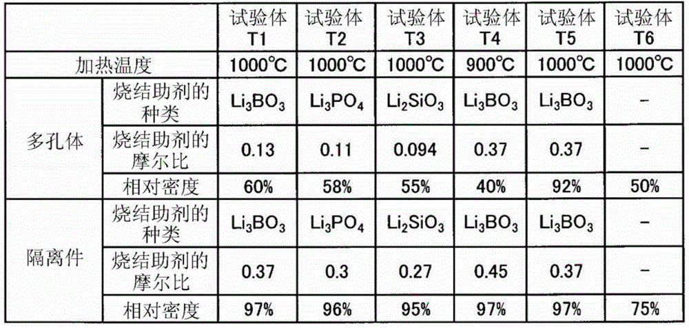
In this example, a test piece in which the separator 3 and the porous body 21 were laminated was prepared by variously changing the heating temperature and the sintering aid in the co-sintering step, and the relative densities of the porous body 21 and the separator 3 were measured. The method for producing the test piece will be described below. The method of measuring the relative density is as described above.
(test body T1)
When producing the test piece T1, first, a powder containing LLZ and Li as a sintering aid were prepared3BO3And an acrylic resin as a pore-forming material, a solvent and a binder. The content of the sintering aid in the mixture for electrodes was adjusted in such a manner that the molar ratio of B atoms with respect to La (lanthanum) atoms of LLZ was 0.13. The electrode mixture was formed into a sheet shape using an applicator to prepare a green sheet as the layer 1. The thickness of layer 1 was 300. mu.m. Incidentally, Li3BO3The melting point of (B) was 820 ℃.
In addition, LLZ-containing powder and Li as sintering aid are prepared3BO3A solvent and a binder. The content of the sintering aid in the mixture for separators was adjusted in such a manner that the molar ratio of B atoms to La atoms of LLZ was 0.37. The separator mixture was formed into a sheet shape using an applicator to prepare a green sheet as the 2 nd layer. The thickness of the 2 nd layer was 300. mu.m.
The 1 st layer and the 2 nd layer thus formed were cut into a desired size, and the two layers were stacked to obtain a laminate. The laminate was subjected to hot isostatic pressing to bond 2 green sheets together, and then heated at the temperature shown in table 1 in the atmosphere to integrally form the separator 3 and the porous body 21. This gave test sample T1. The relative density of the porous body 21 and the relative density of the separator 3 in the test piece T1 are shown in table 1.
(test specimens T2 to T4)
The test pieces T2 to T4 were produced in the same manner as the test piece T1 except that the type and the amount of the sintering aid were changed as shown in table 1. The relative density of the porous bodies 21 and the relative density of the separator 3 in these test pieces are shown in table 1. Li as a sintering aid used in test T23PO4The melting point of (b) is 840 ℃. Li as a sintering aid used in test T32SiO3The melting point of (B) was 1200 ℃.
(test body T5)
The method for producing the test article T5 was the same as the method for producing the test article T1, except that the amount of the sintering aid added to the electrode mixture was the same as the amount of the sintering aid added to the separator mixture. Table 1 shows the relative density of the porous body 21 and the relative density of the separator 3 in the test sample T5.
(test body T6)
The method of producing test T6 was the same as test T1 except that the sintering aid was not added to the electrode mixture and the separator mixture. The relative density of the porous body 21 and the relative density of the separator 3 in the test piece T6 are shown in table 1.
(test specimens T7 to T10)
The test pieces T7 to T10 were produced in the same manner as the test piece T1 except that the type and the amount of the sintering aid were changed as shown in table 2. The relative densities of the porous bodies 21 and the separators 3 in these test specimens are shown in table 2.
(test body T11)
The procedure of test T11 was the same as that of test T1 except that the sintering aid was not added to the electrode mixture. The relative density of the porous body 21 and the relative density of the separator 3 in the test piece T11 are shown in table 2.
(test T12 and test T13)
The method for producing test T12 and test T13 was the same as test T11 except that the heating temperature during firing was set to the temperature shown in table 2. The relative densities of the porous bodies 21 and the separators 3 in these test specimens are shown in table 2.
(test body T14)
The method for producing test T14 was the same as test T1 except that the amount of the sintering aid added and the heating temperature during sintering were changed as shown in table 3. The relative density of the porous body 21 and the relative density of the separator 3 in the test piece T14 are shown in table 3.
The average grain size of the LLZ contained in the porous body 21 and the separator 3 and the electrical conductivity of the test piece were measured for the test pieces T12 and T14 by the following methods.
(average grain size)
The test piece was cut in the direction of lamination of the porous body 21 and the separator 3 to expose the cross section. The cross section was observed with a scanning electron microscope to obtain an SEM image with a magnification of 5000. Fig. 3 shows an SEM image of the porous body 21 in the test specimen T12, and fig. 4 shows an SEM image of the separator 3. Fig. 5 shows an SEM image of the porous body 21 in the test specimen T14, and fig. 6 shows an SEM image of the separator 3. As shown in fig. 3 to 6, the crystals of the LLZ in the porous body 21 and the separator 3 are granular, and the crystals of the adjacent LLZ are connected and integrated with each other.
The maximum diameter was determined for 20 or more crystals randomly selected among the crystals of LLZ present in these SEM images. Then, the average of these maximum diameters was taken as the average grain diameter of the LLZ. Table 3 shows the average grain diameters of LLZ in the porous body 21 of the test body T12, the separator 3 of the test body T12, the porous body 21 of the test body T14, and the separator 3 of the test body T14, respectively.
(conductivity of test body)
The gold paste was applied to both end surfaces of the test piece in the thickness direction, and then sintered at 600 ℃. An impedance measuring device ("1260A" by Solartron corporation) was connected to the test body via these terminals, and the resistance value was measured in a frequency range of 10 μ Hz to 32 MHz. The electrical conductivity was calculated using the resistance value obtained above, the area of the end face in the thickness direction of the test piece, and the thickness of the test piece. The conductivities of test body T12 and test body T14 are shown in table 3.
[ TABLE 1 ]
[ TABLE 2 ]
[ TABLE 3 ]
As shown in table 1, in the production processes of the test pieces T1 to T4, the sintering aid was used for both the porous body 21 and the separator 3. The amount of the sintering aid added to the porous body 21 is smaller than the amount of the sintering aid added to the separator 3. Therefore, in these test bodies, the crystal growth of the LLZ in the porous body 21 can be suppressed while promoting the crystal growth of the LLZ in the separator 3.
On the other hand, in the test body T5, since the kind and amount of the sintering aid contained in the porous body 21 were the same as those of the sintering aid contained in the separator 3, the LLZ in the porous body 21 crystallized and grown in the same manner as the LLZ in the separator 3. As a result, in the test specimen T5, the pores 211 of the porous body 21 disappeared, resulting in an increase in the relative density.
In the test body T6, since the sintering aid was not used for both the porous body 21 and the separator 3, the crystal growth of LLZ was insufficient. Therefore, the relative density of the separator 3 is low.
As shown in table 2, in the test samples T7 to T10, the melting point of the sintering aid used for the porous body 21 was higher than that of the sintering aid used for the separator 3. Therefore, in these test bodies, the crystal growth of the LLZ in the porous body 21 can be suppressed, while the crystal growth of the LLZ in the separator 3 can be promoted.
In the test bodies T11 and T12, only the sintering aid was used for the separator 3, and therefore, the crystal growth of LLZ in the porous body 21 was suppressed and the crystal growth of LLZ in the separator 3 was promoted.
In the test body T13, the heating temperature during sintering was too high, and therefore the LLZ in the porous body 21 crystallized and grown similarly to the LLZ in the separator 3. As a result, in the test specimen T5, the pores 211 of the porous body 21 disappeared, and the relative density increased.
The test piece T14 shown in table 3 was heated at a temperature lower than the 830 ℃. Therefore, in test T14, the LLZ in separator 3 could not be sufficiently crystal-grown, resulting in a decrease in lithium ion conductivity.
The present disclosure is not limited to the above embodiments and experimental examples, and can be applied to various embodiments within a range not departing from the gist thereof.