Disclosure of Invention
The invention aims to provide a calibration control method for a photodynamic therapy device, which meets the requirement of accurate light projection, and the photodynamic device using the calibration control method.
The calibration control method comprises a projection position mapping establishing step and an irradiance calibration step, wherein the projection position mapping establishing step is realized by constructing a back projection mode of a homography matrix to determine mapping of projection position coordinates; the irradiance calibration step comprises the steps of respectively calibrating the modulation parameter and the irradiance and calibrating the light source driving current and the irradiance.
In the step of calibrating the light projection position, the homography matrix is applied to a plurality of effectively divided sub-areas and is used for corresponding an image formed by the image sensor at any point on the spatial plane with the pixel coordinates of a corresponding point in the spatial light modulator so as to realize mapping.
In the irradiance calibration step, the modulation parameters and the irradiance calibration are executed under the condition of determining the working condition of the light source, the light source driving current and the irradiance calibration are executed in a variable way in the controllable range of the spatial light modulator, a matrix is established for each data among the current magnitude of the illumination light source, the modulation parameters of the spatial light modulator array, the pixel position information and the optical power density to generate a corresponding model, and the irradiance calibration step is completed.
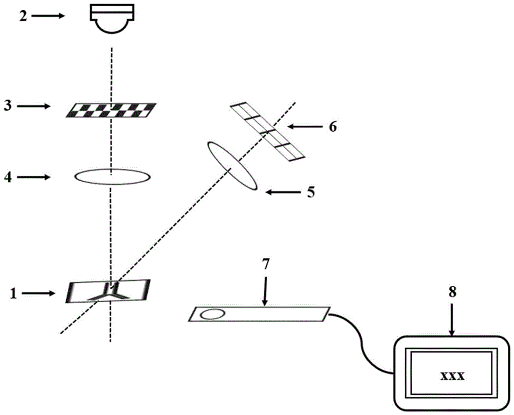
The photodynamic therapy device capable of executing the calibration control method comprises a light projecting part and a shooting part, wherein the light projecting part consists of a treatment light source (2) with a lens, a spatial light modulator (3) and a projection lens (4) which are formed into a coaxial optical system, the treatment light source, the spatial light modulator and the projection lens are in an optical conjugate state, the shooting part comprises a lens (5) and an image sensor (6) which are coaxially arranged, the shooting part forms an inclined angle relative to the axis of the coaxial optical system of the light projecting part, the inclined angle can be adjusted so that the placing positions and the directions of the lens (5) and the image sensor (6) can achieve the maximum imaging, and the displayed image is positioned at the center position of the image sensor.
For best matching of precision, the resolution of the image sensor (6) should not be lower than the resolution of the spatial light modulator and not less than 1024 x 768 pixels.
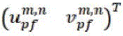
In the calibration, the light projecting unit is controlled to project the feature point array in the light projecting position map establishing step, the image capturing unit captures a sample image with feature point array information, and the spatial light modulator pixel coordinates of the extracted feature points are set to
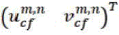
Image sensor pixel coordinates are noted
Wherein m and n are serial numbers and represent the number of rows and columns where the characteristic points are located, m is not more than 9, and n is not more than 17.
In the step of performing irradiance calibration, the light projecting part is controlled to project calibration sequence charts with prototype light spots of different pixel sizes in the irradiance calibration step, so that the optical power meter probe can acquire different irradiance distributions at the sample position.
According to the calibration control method, three-dimensional reconstruction of the surface to be treated is not needed before photodynamic treatment, the calculated amount of back projection is reduced, the feedback speed of the photodynamic treatment device is improved, the device can be operated to realize accurate photodynamic projection after calibration, photodynamic treatment is executed, and the calibration control method is simple and convenient to operate and high in accuracy.
Detailed Description
The apparatus and the method of the invention are described in more detail below with reference to the accompanying drawings and examples, and by way of control of the apparatus. The exemplary embodiments and descriptions of the present invention are provided to explain the present invention and not to limit the present invention.
A system schematic diagram for realizing calibration of a typical photodynamic therapy device applicable to the calibration control method of the present invention is shown in fig. 1, and includes a treatment light source (2) with a lens, a spatial light modulator (3) and a projection lens (4) which are configured as a coaxial optical system, wherein the treatment light source, the spatial light modulator and the projection lens are in an optical conjugate state, and the treatment light source, the spatial light modulator and the projection lens are configured as a light projection part which is a necessary part for treatment implementation of the photodynamic therapy device, and the treatment light source of the specific light projection part generates treatment light with a specific wavelength, and the treatment light can be coupled to the spatial light modulator (3) through the lens, and then irradiated to a sample (1) through the projection lens (4) to output photodynamic projected for treatment.
The treatment light source (2) with the lens can adopt a laser light source or a light-emitting diode light source, and the lens is used for collimation.
The spatial light modulator (3) is of an array type structure, an illumination area projected after passing through the spatial light modulator is divided into a plurality of micro units, such as 1280 × 800, 1024 × 768,800 × 600 and the like, the modulatable parameters of the spatial light modulator comprise transmittance or reflectance and reflection time duty ratio, and the adjusting mode can comprise a transmission mode, a reflection mode, a phase modulation mode and the like.
In order to meet the requirement of calibration control, the photodynamic therapy device also comprises a shooting part which can be attached and installed at a preset position relative to the light projection part, a lens (5) and an image sensor (6) of the shooting part are also coaxially arranged, and an inclined angle is formed relative to the axis of a coaxial optical system of the light projection part, the inclined angle can be adjusted, so that the placement position and the direction of the lens (5) and the image sensor (6) can reach the maximum imaging and the presented image is positioned at the central position of the image sensor, the angle adjustment is the precondition of the operation of the calibration method and can be realized by visual observation, but the feedback is preferably realized by the prior automatic image identification method to determine the accurate position result. In order to achieve the necessary calibration accuracy, the resolution of the image sensor (6) used in the image capturing section should be not lower than the resolution of the spatial light modulator and larger than 1024 × 768 pixels.
Based on the above-described photodynamic therapy apparatus with the imaging part attached, calibration control of the present invention can be realized. The calibration control method mainly comprises a projection position mapping establishing step and an irradiance calibrating step, and particularly determines the mapping of the projection position coordinate by constructing a back projection mode of a homography matrix.
The homography matrix used in the invention refers to a 3 x 3 transformation matrix existing about any space plane by the pixel coordinates of the image sensor (6) and the spatial light modulator (3), and the matrix realizes the correspondence of the pixel coordinates of any point on the space plane in the image sensor (6) and the spatial light modulator (3). In fact, when the calibration sample is an ideal plane, the pixels of the spatial light modulator (3) corresponding to the pixels of the image sensor (6) can be obtained by acquiring only the pixels corresponding to the homography matrix of the ideal plane and the sample light projection area in the imaging unit. However, in practice, an ideal plane can hardly be achieved by using a calibrated sample surface, so that back projection cannot be directly realized by adopting a single homography matrix method, the method is mostly applied to the outer surface of skin in a small area (regarded as a calibration sample) in the specific practice of photodynamic therapy, and such an area has the characteristics of low curvature, relatively fixed position and the like.
According to the effective partitioning mode of the invention, a stepwise bisection method is used for judging to reduce the calculated amount in the partitioning judgment process, namely, firstly, a complete sample area is divided into two parts along the longitudinal direction or the transverse direction, namely, an area A and an area B, a certain pixel point is judged to be positioned in the divided thinning area A or B, after a result is obtained, the thinning area A or B is divided and judged in the same direction (the longitudinal direction or the transverse direction) again until all the spatial light modulators are searched, and the judgment is regarded as finished. Specifically, on acquiring a homography matrix of a certain sub-region, the process is as follows:
(I) firstly, a sample for calibration is fixed under a projection objective of a light projection part, and the height of the projection objective is adjusted to enable a light source (2) to clearly image on the sample.
(II) after the sample is fixed, a clear original image of the sample is photographed by the photographing part, and a schematic sample image is shown in FIG. 4. Then, the spatial light modulator is adjusted to project a predetermined characteristic point array on the projection objective lens, as schematically shown in fig. 2, and the image pickup unit is used to pick up a sample image with the characteristic point array, as shown in fig. 5.
(III) spatial light modulator pixel coordinates with each feature point extracted according to FIG. 2 and FIG. 5
And image sensor pixel coordinates
Where m and n are ordinal numbers, indicating the number of rows and columns in which a feature point is located. Typically, m is not more than 9 and n is not more than 17 to reduce the amount of calculation.
(IV) numbering the sub-regions in FIG. 2 and FIG. 5 respectively by using a rule that every four adjacent feature points form a closed sub-region, wherein the sub-regions with the same number are called corresponding sub-regions. The corresponding sub-regions correspond to the same region in the real three-dimensional space, and the region is approximate to a plane. Therefore, the homography matrix H of each sub-region can be calculated by using the four characteristic points corresponding to the corresponding sub-region
jWherein j is a serial number and represents the jth small region. The process is formulated as follows
Four-point sub-area and
four points formingThe sub-regions of (a) correspond to each other, and the homography matrix of the corresponding sub-region can be obtained by equation (1). In this case, j is 8 × (n-1) + m.
After the judgment of the effective subareas is completed, pixel coordinates corresponding to the spatial light modulator (3) are generated through one or more constructed homography matrixes according to the acquired pixel coordinates of the treatment illumination area in the image sensor (6), so that the light projection position coordinates are converted into the pixel coordinates on the spatial light modulator one by one, and the light projection position mapping is completed.
Although the non-direct-under illumination mode can also use the position mapping establishing mode of the invention, the effect obtained when the actual sample (1) is positioned under the light path of the projection lens is better than that of the non-direct-under projection mode, which is beneficial to ensuring the accuracy and precision.
Furthermore, the calibration control method needs to execute an irradiance calibration step, wherein the corresponding relation between the adjustment parameters of the therapeutic light source (2) and the spatial light modulator (3) and the light irradiance is established in the step to complete calibration. In an exemplary manner, any one or a combination of the following parameters may be adjusted: the drive current of the therapeutic light source (2), the modulation duty cycle of the drive current and the modulation parameters of the spatial light modulator (3) realize the regulation and control of the light irradiance. Typically, under certain therapeutic light source working conditions, the modulation parameters of the spatial light modulator (3) can be controlled by the controller to adjust the grey value of each unit pixel to control the reflectivity or transmittance of the spatial light modulator.
The calibration of the irradiance of the light projection part is accurately realized by depending on a standard optical power meter which is not part of the photodynamic therapy device and does not need to be used as an attachment part, any optical power meter which meets the standard of a measurement range or is calibrated by the standard can be used for the irradiance calibration step, and a specific implementation mode can be as follows:
(I) fixing the optical power meter: the method comprises the steps that an optical power meter probe (7) is placed at a position of a sample (1) and fixed, the probe (7) is connected with data processing equipment such as a computer through an optical power measuring device (8), a spatial light modulator is controlled to project any one of calibration chart sequences after passing through a projection lens, and the calibration chart sequences are clearly imaged on the optical power meter probe (7) through a projection objective, wherein the calibration chart sequences can be shown in figure 3 or other preset regular patterns;
(II) setting the driving current of the light source of the light projection part, wherein the light projection part sequentially projects a calibration chart sequence to enable the illumination range to gradually expand the illumination radius to the image boundary by taking the center as the circle center, and the corresponding change value is recorded by an optical power meter in the process. The projected calibration chart sequence uses, for example, 16 images of FIG. 3;
(III) using the light projector to project a full white image with a gray scale value of 255, adjusting the illumination source drive current to modulate each irradiance within a variable range of modulation parameters such as transmittance, reflectance of a variable spatial light modulator, typically as represented by gray scale values of 0 to 255, using 18 gray scale images with a gray scale interval of 15, using an optical power meter to record the irradiance at different illumination source currents. In the process, the optical power meter should obtain 16 × 18 records of variation values.
(IV) respectively finishing (a) processing the irradiance obtained by the sequence in the figure 3, and obtaining a pixel light irradiance distribution model of different areas from the center to the edge according to the change rule of the illumination range in the sequence in the figure 3;
(b) performing polynomial fitting on the optical power densities measured by the modulation parameters of different spatial light modulators to obtain a mapping relation between the modulation parameters and irradiance; and
(c) and carrying out polynomial fitting on the optical power densities under different lighting source driving currents to obtain a lighting source current and irradiance mapping relation.
And establishing a matrix for each data among the current magnitude of the illumination light source, the modulation parameters of the spatial light modulator array, the pixel position information and the optical power density to generate a corresponding model, namely finishing the irradiance calibration step.
Before any photodynamic therapy device is treated, the calibration method of the invention is used for executing calibration so as to realize accurate light projection, and the implementation process is as follows when a subcutaneous blood vessel is treated as an example:
(I) setting light source with pure illumination light power safe for treating sample, performing image segmentation on original image of sample, and extracting corresponding pixel (u) on image sensorcv vcv)T. The result of the division is shown in fig. 6, where the white parts are the pixels (u) on the spatial light modulatorcv vcv)TAnd the light projection position mapping is realized.
(II) judging the sub-regions of the extracted pixels on the image sensor one by one, and writing the pixel coordinates of the sample of the sub-region with the assumed number j on the image sensor
(III) obtaining the pixel coordinates of the spatial light modulator of the light projection part corresponding to the blood vessel by using the homography matrix corresponding to the sample pixel, namely
Completing the construction of the light projection position mapping;
(IV) setting the gray value of the pixel corresponding to the spatial light modulator of the light projection part corresponding to the sample position which does not need light projection as 0, setting the corresponding pixel modulation parameter and/or the driving current of the illumination light source for the spatial light modulator of the light projection part corresponding to the sample position which needs treatment according to the position and the device irradiance calibration model which are obtained in advance, and obtaining a typical projection image as shown in FIG. 7.
(V) projecting the projected image obtained In (IV) with the sample accurately irradiated, and the relative positions of the projected light and the sample in the imaging in the photographing section are shown in fig. 8.
After the calibration control, the light source can be adjusted to be the condition for applying the therapeutic light, the shooting part keeps continuously shooting the sample blood vessel change images obtained at intervals during/after the implementation of the light irradiation in the treatment process, and when the image change reaches the preset condition, the light projection is stopped to ensure the safety. The predetermined condition may be that a certain preset value, for example 50% of the pixel size of the original image size, is reached, which should be confirmed in a manner dependent on the medical treatment evaluation.
According to the calibration method, effective calibration can be carried out on a treatment target before any treatment, and after calibration, the computer adjusts the modulation parameters of each micro unit of the spatial light modulator (3) according to the acquired image information, so that the treatment time, irradiance and treatment illumination duty ratio of a treatment illumination area and each micro unit are controlled, accurate light projection is realized, the safety in the treatment process is ensured, quantitative research of a PDT mechanism is facilitated, and the requirement of research on the damage dose-effect relationship of photochemical damage and thermal damage to different tissues in treatment is met. Standard optical power meter probes (7) are placed at the samples intended to be treated, and it will be understood by those skilled in the art that for photodynamic devices used at fixed target locations, if the treatment light source does not fluctuate or decay beyond the standard, i.e. without repeating the irradiance calibration step, it is sufficient to use the calibration model records that have been determined. Similarly, the irradiance calibration step and the projection position mapping establishing step involved in the calibration control method of the invention are not related in front and back.
The foregoing is illustrative of the present invention and is not to be construed as limiting thereof in any way. Any simple modification, equivalent change and modification made to the above embodiments according to the technical spirit of the present invention still fall within the scope of the technical solution of the present invention.