The present application is a divisional application of the application having application number 201680007036.X, filed 2016, 1, 14, entitled "tool and method for screwing a lid onto a container" entitled "screw lid.
Background
Screw caps for containers having a threaded neck have been known in the art for a long time.
Typically, both the screw cap and the neck are made of a polymeric material, the neck comprising one or more complementary threaded portions for screwing the cap onto the neck.
In the food packaging industry, packaging containers having a bottle-like shape with a main portion of laminate paper material and a top portion of polymer material comprising a threaded neck portion are well known. An example of such a packaging container is Tetra TopTM,Tetra EveroTMAnd Tetra Evero AsepticTMWherein the latter further comprises an oxygen barrier layer in the form of an aluminium foil as part of the laminate material to allow a longer storage time of the food contained in the packaging container.
After laminating the web of paper stock with several outer polymer materials, folding and splicing to form a hollow packaging container body on which a top part comprising a threaded neck part is injection moulded, as can be seen from the packaging container described in the preceding paragraph, the body may be of a different material than the top part. In a subsequent step, a screw capping unit screws a screw cap, typically made of a polymer material and having a thread complementary to the threaded neck, onto the neck of the packaging container. In a subsequent step, the hollow side of the packaging container is filled with the food to be contained, and then the hollow end of the container is folded and sealed. It should be mentioned that in one possible known realisation of the capping process, the hollow packaging container body comprising the injection moulded top is fed into a rotating drum and rotated to face the screw cap holder while feeding the screw cap to the screw cap holder at a certain distance. When both the packaging container and the screw cap holder are locked in their radial position, the screw cap is moved in a rotating manner towards the top of the packaging container and screwed onto the neck of the packaging container.
Experience has shown that a small part of the packaging containers so closed show misalignment between the cap and the neck of the container.
One cause of misalignment may be storage conditions of the lid, such as temperature and moisture, which may affect the coefficient of expansion of the lid material. Another reason may be that the relative position of the helix application tool (chuck) and the screw cap is inaccurate. Such misalignment may result in the cap being applied to the neck slightly askew, thus resulting in an insufficiently sealed container, a threaded portion on the neck, and the cap itself being damaged or being too easy to open the bottle. Containers with these deviations need to be discarded.
In any event, it is desirable to address at least some of the aforementioned problems, resulting in better sealing of the lidded packaging containers and lower discard rates.
Disclosure of Invention
At least some of the problems of the prior art are solved by a screw cap according to claim 1 of the present invention.
Preferred embodiments are given in the dependent claims.
According to one aspect of the invention, a solution is provided by a screw cap for a container having a threaded neck, wherein the screw cap comprises a base having a top surface and a bottom surface; an annular portion rising from the base portion having an inner surface and an outer surface; at least one first threaded portion disposed on an inner surface of the annular portion, wherein the base portion includes at least one engagement portion, such that the screw cap is configured to engage a tool with the at least one complementary engagement portion during alignment of the screw cap with the complementary threaded neck.
In one embodiment, the engagement portion of the screw cap may be located on an inner surface of the base. The inner surface is defined as the surface facing the base of the pouring opening of the container defined by its neck.
In another embodiment, the above-mentioned engaging portion may be at an outer surface of the base of the screw cap, wherein the outer surface is defined as the surface of the base facing away from the pouring opening of the container.
While the engagement portion may have many variations, in one embodiment of the screw cap, the engagement portion may include at least one protrusion.
Otherwise, the engagement portion may also be formed by at least one protrusion and a recess adjacent to the protrusion. It is contemplated to have at least one protrusion and recess located in close proximity to each other. In this way, the movement of the tool is reduced as it engages with the complementary shoulder or shoulders of the recess or recesses of the engagement portion.
In order to obtain a better alignment of the screw cap with the threaded neck of the packaging container as described above, the at least one protrusion of the engagement portion may be vertically aligned with an initial portion of the at least one threaded portion on the screw cap.
In one variation, there may be three pairs of protrusion-recesses along the circumference of the inner surface of the screw cap, wherein one end of each protrusion is vertically aligned with the beginning of three thread portions arranged along the inner surface of the annular portion.
Not according to another aspect of the invention. The tool is adapted for feeding a screw cap as described previously to a screw cap holder and comprises a main body, a top end portion in contact with the main body, the top end portion being arranged to engage the screw cap, a bottom end portion in contact with the main body, the bottom end portion comprising means for mounting the tool to the tool holder and at least one engagement portion for engaging with at least one complementary engagement portion on the screw cap when the screw cap is rotated around the tool.
In one embodiment of the tool, the engagement portion may be a shoulder.
In this way, one or more shoulders of the tool will engage complementary engagement portions on the screw cap and lock the position of the screw cap.
Corresponding to the last paragraph concerning the screw cap's embodiment of the screw cap, the tip section of the tool may be made such that it comprises three shoulders arranged along the circumference of the tip section, wherein the shoulders are radially aligned with the center of the tip section.
The screw cap may be applied to a packaging container for food products, which packaging container itself comprises a body portion and a threaded neck portion of a polymer material.
Not according to another aspect of the invention is defined by a method for aligning a threaded screw cap with a complementary threaded neck portion of a packaging container.
According to the method, the screw cap holder is positioned such that it faces the screw cap feeding tool from which the screw cap holder receives the screw cap. The screw cap holder is rotated until there is engagement between the engagement portion in the screw cap and the complementary engagement portion in the feeding tool. The rotational position of the screw cap holder is recorded and the screw cap is disengaged from the feeding tool.
It may also be mentioned that the screw cap holder may be moved towards the feeding tool, or that both the screw cap holder and the feeding tool may be moved towards each other.
Disengagement may be performed by rotating the screw cap out of engagement and retracting the screw cap from the feeding tool.
Finally, a further aspect not according to the invention is defined by a method for screwing a screw cap onto a neck of a packaging container comprising at least one complementary threaded portion. The method is carried out by the following steps: the screw cap holder holding the screw cap is positioned such that it faces the threaded portion of the packaging container and aligns their symmetry axes. The screw cap holder rotates the screw cap to a predefined rotational position recorded during the alignment step with the screw cap feeding tool. The screw cap holder is moved towards the packaging container or vice versa, the screw cap holder being rotated, whereby the screw cap is rotated in a direction to engage with the threaded portion of the packaging container, such that the cap is screwed onto the threaded portion.
In this way, the screw cap will always have a precisely defined rotational position relative to the neck of the packaging container, on which neck the screw cap is screwed down, and misalignment is minimized.
Detailed Description
Embodiments of the present invention will be described in more detail below with reference to the accompanying drawings so that those skilled in the art can implement the invention. This invention may, however, be embodied in many different forms and should not be construed as limited to the embodiments set forth herein. The embodiments do not limit the invention, but the invention is only limited by the appended patent claims. Furthermore, the terminology used in the detailed description of the particular embodiments illustrated in the accompanying drawings is not intended to be limiting of the invention.
Fig. 1 shows a cap application assembly 100 for applying a screw cap onto a packaging container. It should be mentioned here that once the web of packaging laminate is cut and folded into a hollow packaging container body and once the polymeric portion containing the threaded neck is injection moulded on top of the packaging container, it is fed to the lid application assembly 100. The lid application assembly 100 comprises a drum 130 rotatable about an axis a-a and a tubular opening 132 for receiving a packaging container. Further, the cap application assembly 100 comprises a stripper unit 110, the stripper unit 110 feeding the packaging containers from the drum 130 to a capping station where screw caps are applied to the threaded necks of the packaging containers. The stripper unit 110 then takes the packaging container away from the decapping station 120 and places a new packaging container there. When a new packaging container is fed to the capping station 120, the screw cap application unit 140 is moved downwards along axis B-B and forwards along axis C-C in the direction of the arrow in fig. 1 (forward meaning towards the drum 130) to pick up a screw cap from a screw cap handling unit (not shown). The screw cap is fed onto a piston (not shown) to a screw cap holder or chuck 150. The screw cap application unit 140 is then moved upwardly along axis B-B and moved rearwardly in the direction of the arrow along axis a-a (i.e., away from the drum 130) to position the chuck 150 holding the screw cap in front of the package in the capping station 120. Finally, the screw cap application unit 140 rotates the chuck 150 while the packaging container is moved toward the chuck 150. In this way, the screw cap held in the chuck 150 is screwed onto the threaded neck of the packaging container. Once the screwing step has been completed, the stripper unit 110 moves the thus closed packaging container away from the capping station 120 to a package filling step, in which the packaging container, which is hollow on the end opposite to the cap end, is filled with the food product, and in which the open end of the packaging container is folded together and sealed. At the same time, a new packaging container is fed to the capping station 120 and the screw cap application cycle begins again.
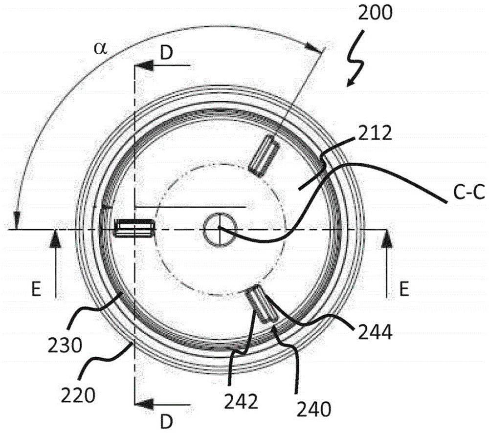
Fig. 2A is a top view of a screw cap 200 for a packaging container according to an embodiment of the present invention. As can be seen in fig. 2B, the exemplary screw cap basically comprises a base 210 having a top surface 212 and a bottom surface 214, the top surface 212 being oriented towards an open nozzle of a packaging container (not shown) to which the screw cap is to be applied. The screw cap further comprises a first raised annular portion 220 extending from the base 210 in the direction of its top surface 212 and along the circumference of the base. This annular portion is held by a cap holder 150 in the cap application unit described in fig. 1 when ready to be screwed onto the neck of a packaging container of the type mentioned in the background of the invention. The outer surface of the ring portion 220 may or may not include vertical ribs to facilitate gripping of the screw cap when the closed packaging container is to be opened. In addition, the exemplary screw cap 200 also includes a second raised annular portion 230 centered about the central axis C-C of the screw cap 200 and extending to a height substantially lower than the height of the first raised annular portion 220.
In addition, screw cap 200 according to the embodiment of fig. 2A further comprises an engagement portion 240, engagement portion 240 comprising three pairs of protrusions 242 and recesses 244 arranged in top surface 212. As shown in fig. 2A, the three engagement portions 240 are arranged on a circumference centered around an axis of symmetry C-C of the screw cap 200, wherein the axis of symmetry C-C is perpendicular to a plane in which the bottom surface lies. In this particular embodiment, the protrusion 242 and the recess 244 are arranged parallel to and proximate to each other. Even if the angular pitch represented by the angle α between the three engaging portions 240 in fig. 2A is about 120 degrees, the angular pitch need not be uniform, nor does the number of engaging portions 240 need to be restricted to three. Any number of engagement portions without uniform angular spacing may be arranged.
Fig. 2B shows a cross-sectional view of screw cap 200 of fig. 2A along axis a-a. The screw cap 200 comprises a plurality of threads on the inner surface 222 of the first raised annular portion 220, of which a first thread 252 and a second thread 254 are shown, which make it possible to screw the cap 200 onto complementary threads arranged on the neck of a packaging container, thereby closing the container. The thread is descending when seen from the top surface 212 in the direction of the neck of the packaging container (not shown). In one possible variation of screw cap 200, there are three threads, one of which is not shown in fig. 2B, and each of which is aligned with one of the engagement portions 240 shown in fig. 2A. The threads and the engagement portion 240 are aligned such that the start of each thread (e.g., start 255 of the second thread 254) is vertically aligned with an end of the protrusion 242 of the engagement portion 240. The effectiveness of this configuration will be described below.
The purpose of the engagement portion 240 is to engage a corresponding cap loading tool (e.g., the loading piston 300) so that a shoulder disposed on the top of the loading piston 300 can engage the engagement portion 240. During a screw cap alignment procedure (to be described further below), the engagement between the screw cap 200 and the loading piston 300 will prevent further rotation of the screw cap 200. When locked in the rotational direction due to the engagement, the locked screw cap position can be used in a later screw cap application process to reach the start of the complementary threaded neck of the packaging container. The use of the protrusion 242 and the recess 244 for the engagement portion 240 in the screw cap has the additional advantage that the engagement with the complementary shoulder of the loading piston 300 is achieved with very little play. Accordingly, the rotational position of the screw cap 200 achieved when engaged with the loading piston 300 can be determined more accurately. Thus, when applying the screw cap 200 to a complementary threaded neck of a packaging container, the reduced play between the engagement portion 240 of the screw cap 200 and the shoulder of the loading piston 300 will increase the precision, and thus a better sealing of the container may be achieved.
Such an exemplary loading tool is shown in fig. 3A-3C. Which will be explained in the following text.
Fig. 2C shows a cross-section of screw cap 200 of fig. 2A along axis E-E, in which an enlarged view of one of the previously discussed engagement portions 240 is particularly shown.
As can be seen from the enlarged view of fig. 2C, the engagement portion 240 includes a protrusion 242 having a vertical portion and a horizontal portion and another falling portion. Further, the protrusion 242 includes a recess 244 adjacent to the vertical portion of the protrusion 242, wherein the recess 244 includes a descending portion and an arcuate portion. This configuration of the engagement portion ensures that the shoulder of the loading piston, which engages with the engagement portion 240 of the screw cap 200, remains in the arcuate portion of the recess 244, with its further rotational movement being limited by the vertical portion of the projection 242, with very little play. However, it is possible to manufacture the screw cap 200 comprising only protrusions as engagement portions, which will allow some play between the shoulder of the loading piston and the engagement portions of the screw cap, but still result in a satisfactory alignment between the screw cap and the neck of the packaging container.
Next, fig. 3A shows an exemplary embodiment of the loading piston 300, the loading piston 300 being used as a tool to push the cap 200 into the chuck and orient the cap 200.
As shown in fig. 3A, the loading piston 300 has a cylindrical shape including a cylindrical body 310, a top portion 320, and a base portion 330. The top 320 includes a conical portion 328, the top of the conical portion 328 including an annular portion 322, the annular portion 322 having a shoulder 324 disposed along its circumference as a complementary engaging portion. The loading piston 300 also includes a recess 326 formed in the top 320 of the loading piston 300 so as not to contact a slight protrusion in the center of the screw cap, such as shown in fig. 2B.
In this embodiment of the loading piston 300, there are three shoulders 324, the shoulders 324 functioning to engage with the engagement portion 240 on the screw cap 200 in fig. 2A. Although in this embodiment the loading piston 300 has three shoulders to match the number of engagement portions 240 on the screw cap, the loading piston 300 may have any shape for the complementary engagement portions and any number of these complementary portions manufactured such that they are able to engage the engagement portions on the screw cap. It should be kept in mind that the engagement portions may have a different shape than that shown in fig. 2C, as long as they are capable of engaging complementary engagement portions in the loading piston 300, resulting in a restricted movement of the loading piston 300 in the screw cap when the two are engaged.
With respect to the base 330 of the loading piston 300, it includes a tapered bore 336 and a tapered mouth 334 for attachment to a feeding unit configured to feed a new screw cap into the screw cap holder 150 shown in fig. 1.
A spring (not shown) may be disposed in the tapered bore 336, wherein the servo motor may use tension to rotate the chuck 150 relative to the loading piston in order to detect the location of engagement between the shoulder 324 of the loading piston 300 and the corresponding engagement portion 240 in the screw cap 200.
However, the presence of a spring in the tapered bore 336 is not necessary for this operation.
It may also be mentioned that they may be sets of chucks, each chuck being adapted to tighten caps of different sizes and possibly to adapt its complementary engagement portion to achieve engagement with different engagement portions in different screw caps.
Next, the process of orientation and alignment of the screw cap with respect to the threaded neck of the packaging container will be explained by means of the flow charts shown in fig. 4 and 5.
Fig. 4 shows the steps of a lid orientation method not according to an embodiment of the invention. When the screw cap is transported by the loading piston to the chuck in the cap application unit depicted in fig. 1, the rotational position of the screw cap with respect to its central axis C-C and its rotational position with respect to the chuck is unknown. As previously described herein, such an undefined rotational relationship may lead to a misalignment between the screw cap and the complementary threaded portion on the neck of the packaging container when the cap application unit screws the cap onto the neck. The purpose of the cap orientation is thus to achieve a precisely defined rotational position of the cap, which can later be used for screwing the cap onto the packaging container in alignment.
Now, at step 410, a screw cap (e.g., screw cap 200) as shown in fig. 2A-2C is loaded onto the piston and held stationary there. The piston moves along axis C-C towards the chuck. Meanwhile, after the cap is loaded into the chuck, a servomotor on which the chuck (e.g., chuck 300 shown in fig. 3A-3C) is mounted rotates the chuck about its central axis. Depending on the structure of the cap applying unit, the servo motor mounted with the chuck may be moved toward the fixed piston to which the screw cap is loaded, or the servo motor together with the chuck and the piston together with the screw cap may be moved toward each other.
In step 430, the servomotor checks whether the engagement portion of the screw cap is in contact with a complementary engagement portion in the loading tool. If no special means for detecting the build-up of torque is provided, it can be detected as a stop of the movement of the chuck. The engagement between the screw cap and the loading tool also causes the servo motor to stop. The rotational position of the chuck is then recorded, for example, in an internal memory connected to a servo motor, at step 440. If engagement between the chuck and the screw cap cannot be detected, the servo motor is stopped and a capping procedure is performed without knowledge of the rotational alignment.
In a next step 450, the screw cap is disengaged from the engagement portion of the loading piston by rotation of the servo motor in the opposite direction of disengagement.
Finally, at step 460, the loading piston is moved in a direction away from the chuck and cap along the central axis C-C.
After completion of these steps, the chuck will be able to have a precisely defined rotational position relative to the screw cap, minimizing the risk of misalignment between the screw cap and the threaded neck of the packaging container.
Fig. 5 shows in flow chart form a screw cap application method not according to an embodiment of the invention.
At step 510, the servomotor retrieves the previously stored rotational position of the chuck relative to the screw cap and rotates the chuck to a new position relative to the stored chuck so that they are in perfect alignment with each other when the cap and neck are engaged.
At step 530, the servomotor locks the chuck position to a specific position on the packaging container. This can be done with the aid of a virtual camshaft. In general, using a true mechanical camshaft, it is possible to determine how the other shaft should rotate relative to the position of the camshaft. In this case, such a mechanical camshaft is virtual and the other servo motor camshaft pivots relative thereto. In this way, the start of the thread on the screw cap is aligned with a specific rotational position of the neck of the packaging container, so that when the cap is screwed onto the neck, it reaches a predetermined point on the neck.
Finally, at step 540, the lid is screwed onto the packaging container using the steps described in fig. 1.
It should be mentioned that although the engagement portions in the screw cap and the loading piston have been described with respect to one embodiment, the screw cap and the loading piston may also be manufactured such that the engagement portions are located at the outer surface 212 of the screw cap. Furthermore, the engagement portion in the screw cap may need to be vertically aligned with the start of the thread in the cap, but may be located at a rotational distance away from it. Also, instead of the protrusions and recesses being located in the screw cap, they may instead be located on the loading piston, while the complementary engagement portions may be located in the screw cap.