Port cargo tray with reinforcing structure
Technical Field
The invention relates to the technical field of cargo pallets, in particular to a port cargo pallet with a reinforced structure.
Background
Pallets are media for converting static goods into dynamic goods, are cargo platforms, and are movable platforms, so that even if the goods which are not flexible are placed on the ground, the mobile goods can be obtained immediately after being loaded on the pallets, and the mobile goods can be obtained.
However, current tray is when the transportation goods, and stability is relatively poor, and the unexpected rocking that produces when the staff removes the tray can cause the goods to drop, and when the transportation fragile article, when the staff put down the tray, the goods damage can be caused to the while.
Disclosure of Invention
Technical problem to be solved
In view of the deficiencies of the prior art, the invention provides a port cargo pallet with a reinforced structure, which solves the problems in the background art.
(II) technical scheme
In order to achieve the purpose, the invention is realized by the following technical scheme: the utility model provides a harbour goods tray with reinforced structure, includes the bottom plate, one side fixedly connected with supporting shoe of bottom plate, one side fixedly connected with bracing piece of bottom plate, one side swing joint of bracing piece has the fly leaf, one side fixedly connected with movable cover of fly leaf, one side swing joint fixed strip of movable cover, the spring groove has been seted up to one side of fixed strip, one side fixedly connected with spring in spring groove.
Optionally, one side fixedly connected with of fly leaf deposits the frame, one side fixedly connected with of depositing the frame protects the pad.
Optionally, a sliding groove is formed in one side of the supporting rod, and a sliding block is movably connected to one side of the sliding groove.
Optionally, one side of the sliding block is fixedly connected with a connecting column, and one side of the connecting column is provided with a threaded hole.
Optionally, one side of the threaded hole is movably connected with a bolt, and one side of the connecting column is fixedly connected with a fixing plate.
Optionally, a storage groove is formed in one side of the fixing plate.
(III) advantageous effects
The invention provides a port cargo tray with a reinforced structure, which has the following beneficial effects:
1. this harbour goods tray with reinforced structure through the setting of fly leaf, movable cover and spring, during the use, on the fly leaf of tray is deposited the goods with the staff, because the setting of movable cover and spring can prevent that the staff from when placing the tray when the transportation fragile article, because the dynamics causes the damage to the goods too big, makes things convenient for the staff to place the goods, has reached the purpose of protection goods safety.
2. This harbour goods tray with reinforced structure, through bracing piece, fixed plate and the setting of depositing the frame, during the use, the bracing piece can provide certain limiting displacement when the staff deposits the goods with the setting of depositing the frame, prevents that the staff from when removing the tray, and the goods is owing to acutely rocking and cause the goods to drop, and the setting of fixed plate can play certain fixed action to the goods, has reached the effect of fixed goods.
Drawings
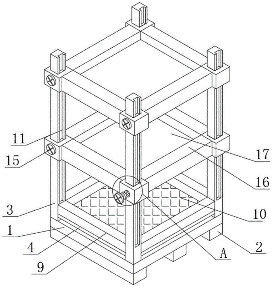
FIG. 1 is a perspective view of the structure of the present invention;
FIG. 2 is a cross-sectional view of the spring connection of the present invention;
FIG. 3 is an enlarged schematic view of the structure of FIG. 1 at A.
In the figure: 1. a base plate; 2. a support block; 3. a support bar; 4. a movable plate; 5. a movable cover; 6. a fixing strip; 7. a spring slot; 8. a spring; 9. a storage frame; 10. a protection pad; 11. a chute; 12. a slider; 13. connecting columns; 14. a threaded hole; 15. a bolt; 16. a fixing plate; 17. and (7) a storage tank.
Detailed Description
The technical solutions in the embodiments of the present invention will be clearly and completely described below with reference to the drawings in the embodiments of the present invention, and it is obvious that the described embodiments are only a part of the embodiments of the present invention, and not all of the embodiments.
Referring to fig. 1 to 3, the present invention provides a technical solution: a port cargo tray with a reinforced structure comprises a bottom plate 1, wherein a supporting block 2 is fixedly connected to one side of the bottom plate 1, a supporting rod 3 is fixedly connected to one side of the bottom plate 1, a movable plate 4 is movably connected to one side of the supporting rod 3, a movable cover 5 is fixedly connected to one side of the movable plate 4, a fixed strip 6 is movably connected to one side of the movable cover 5, a spring groove 7 is formed in one side of the fixed strip 6, and a spring 8 is fixedly connected to one side of the spring groove 7;
through the arrangement of the movable plate 4, the movable cover 5 and the spring 8, when the tray is used, a worker stores goods on the movable plate 4 of the tray, and due to the arrangement of the movable cover 5 and the spring 8, the damage to the goods caused by overlarge force when the pallet is placed by the worker during transportation of fragile goods can be prevented, the goods can be conveniently placed by the worker, and the purpose of protecting the safety of the goods is achieved;
one side of the movable plate 4 is fixedly connected with a storage frame 9, one side of the storage frame 9 is fixedly connected with a protection pad 10, one side of the support rod 3 is provided with a sliding groove 11, one side of the sliding groove 11 is movably connected with a sliding block 12, one side of the sliding block 12 is fixedly connected with a connecting column 13, one side of the connecting column 13 is provided with a threaded hole 14, one side of the threaded hole 14 is movably connected with a bolt 15, and one side of the connecting column 13 is fixedly connected with a fixing plate;
through the arrangement of the supporting rod 3, the fixing plate 16 and the storage frame 9, when the tray is used, the arrangement of the supporting rod 3 and the storage frame 9 can provide a certain limiting effect when a worker stores goods, so that the goods are prevented from falling off due to severe shaking when the worker moves the tray, and the arrangement of the fixing plate 16 can fix the goods to a certain extent, so that the goods are fixed;
one side of the fixing plate 16 is provided with a storage groove 17.
In the invention, the working steps of the device are as follows:
1. the movable plate 4, the movable cover 5 and the spring 8 are matched, when the tray is used, a worker stores goods on the movable plate 4 of the tray, and due to the arrangement of the movable cover 5 and the spring 8, when the tray is placed by the worker during transportation of fragile goods, the damage to the goods due to overlarge force can be prevented, the goods can be conveniently placed by the worker, and the purpose of protecting the safety of the goods is achieved;
2. bracing piece 3, fixed plate 16 and the collocation work of depositing frame 9, during the use, bracing piece 3 and the setting of depositing frame 9 can provide certain limiting displacement when the staff deposits the goods, prevent that the staff from when removing the tray, and the goods is owing to acutely rocking and cause the goods to drop, and fixed plate 16's setting can play certain fixed action to the goods, has reached the effect of fixed goods.
The above description is only for the preferred embodiment of the present invention, but the scope of the present invention is not limited thereto, and any person skilled in the art should be considered to be within the technical scope of the present invention, and the technical solutions and the inventive concepts thereof according to the present invention should be equivalent or changed within the scope of the present invention.