Disclosure of Invention
In order to solve the problems, the invention provides an ultra-large-diameter planar reflection array antenna which can realize flexible beam scanning, is easy to process and has low cost.
In order to achieve the purpose, the technical scheme of the invention is as follows:
the invention relates to an ultra-large-caliber planar reflection array antenna which comprises an upper computer, a feed source, a control module and more than two sub-reflecting surfaces;
the feed source is placed in front of the ultra-large-caliber planar reflection array antenna, and a 3dB wave beam of the feed source just covers the array area;
each sub-reflecting surface is the same active plane reflecting surface and is matched with a corresponding pitching rotating shaft, an azimuth rotating shaft, a front and back moving platform and a base, wherein the front and back moving platform is arranged on the base;
the upper computer is used for giving a reflecting beam pitch angle and a reflecting beam azimuth angle to the control module after the feed source starts to transmit beams to the array antenna and finishes a scanning angle until the scanning beams cover the whole airspace;
the control module is used for calculating the pitching and azimuth of the sub-reflecting surface and the front and back mechanical motion amount according to a given reflecting beam pitching angle and a given reflecting beam azimuth angle given by the upper computer and sending the pitching and azimuth and front and back mechanical motion amount to the pitching rotating shaft, the azimuth rotating shaft and the front and back motion platform;
the pitching rotating shaft, the azimuth rotating shaft and the front and back motion table receive the mechanical motion amount sent by the control module to control the pitching rotation, the azimuth rotation and the front and back motion of the sub-reflecting surface so as to complete a scanning angle;
the calculation method of the pitching, azimuth and fore-and-aft mechanical motion quantity is specifically as follows:
sub-reflecting surface pitching angle thetam:
Sub-reflecting surface azimuth angle phim:
Front and rear step z of sub-reflecting surfacem:
Wherein:
theta is the pitch angle of the reflected beam, phi is the azimuth angle of the reflected beam, R is the distance between the feed source and the reflecting surface, and lambdacIs the carrier wavelength.
Wherein the azimuth rotating shaft of the sub-reflecting surface is arranged on the base.
Wherein the azimuth rotation axis of the sub-reflecting surface is on the reflecting surface.
Has the advantages that:
the plane reflection array antenna of the invention replaces a parabolic curved surface reflection surface with a plane reflection array surface, and has the advantages of flexible beam scanning, easy processing, low cost and the like. The invention combines a plurality of active sub-reflecting surfaces, realizes mechanical phase control by using the mechanical motion of the sub-reflecting surfaces, namely controls the direction of a reflecting beam by using the mechanical motion of each sub-reflecting surface, realizes the direction control of the reflecting beam of a main reflecting surface by the mechanical motion of three degrees of freedom, namely pitching rotation, azimuth rotation and front-back motion of each sub-reflecting surface, and synthesizes all the reflecting beams in the same phase to realize large-angle scanning. Because of adopting mechanical phase control, when the direction of the reflected wave beam is controlled, an electronic phase control assembly of the micro-strip plane reflecting surface antenna is not needed, the grating lobe effect can not occur, the array element spacing is not limited any more, and the cost for constructing the reflecting array surface with the ultra-large caliber is reduced.
Detailed Description
In order to make the technical solution of the present invention better understood, the technical solution of the present invention will be clearly and completely described below with reference to the accompanying drawings in the embodiments of the present invention.
The invention relates to an ultra-large-caliber planar reflection array antenna based on a large mechanical phase control reflection array. The large mechanical phase control reflective array is a large reflective surface formed by a plurality of active plane sub-reflective surfaces, and large-angle scanning of reflected beams of a main reflective surface is realized through mechanical movement of three degrees of freedom, namely pitching rotation, azimuth rotation and back-and-forth movement of each sub-reflective surface. The pitching rotation and the azimuth rotation realize the directional control of the reflected wave beams, and the back-and-forth movement realizes the reflection phase difference control, so that the reflected wave beams are synthesized in the same phase space. Through the spatial in-phase synthesis of the reflected beams of each sub-reflecting surface, the invention can realize large-angle scanning with a pitch angle of 0-20 degrees and an azimuth angle of-20 degrees.
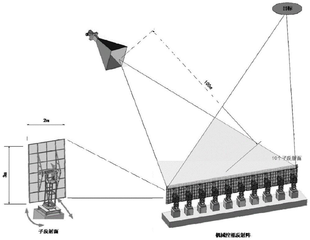
The simulation diagram of the ultra-large-caliber reflector antenna is shown in figure 2 and comprises an upper computer, a feed source, a control module and a plurality of sub reflectors; each sub-reflecting surface is the same active plane reflecting surface and is matched with a corresponding pitching rotating shaft, an azimuth rotating shaft, a front and back moving platform and a base, wherein the front and back moving platform is arranged on the base;
the upper computer is used for giving a reflecting beam pitch angle and a reflecting beam azimuth angle to the control module after the feed source starts to transmit beams to the array antenna and finishes a scanning angle until the scanning beams cover the whole airspace;
the control module is used for calculating the pitching and azimuth of the sub-reflecting surface and the front and back mechanical motion amount according to a given reflecting beam pitching angle and a given reflecting beam azimuth angle given by the upper computer and sending the pitching and azimuth and front and back mechanical motion amount to the pitching rotating shaft, the azimuth rotating shaft and the front and back motion platform;
the pitching rotating shaft, the azimuth rotating shaft and the front and back motion table receive the mechanical motion amount sent by the control module to control the pitching rotation, the azimuth rotation and the front and back motion of the sub-reflecting surface so as to complete a scanning angle;
antenna scanning is realized through the cooperative mechanical motion of three degrees of freedom of pitching rotation, azimuth rotation and back-and-forth movement of the sub-reflecting surface. The sub-reflecting surfaces in the azimuth direction and the elevation direction are combined to form a two-dimensional reflecting array antenna; the feed source is placed in front of the ultra-large-diameter plane reflection array antenna, and 3dB wave beams of the feed source just cover the array area. The working mode of the ultra-large diameter reflector antenna is shown in figure 3.
The sub-reflecting surface can perform mechanical motion with three degrees of freedom and is respectively controlled by a pitching rotating shaft, an azimuth rotating shaft and a front-back moving platform. The structure has two design methods, namely a first type sub-reflecting surface with the azimuth rotating shaft on the base as shown in figure 4 and a second type sub-reflecting surface with the azimuth rotating shaft on the reflecting surface as shown in figure 5.
When the ultra-large-caliber plane reflection array antenna works, beams are transmitted to the array antenna by the feed source, and the three-degree-of-freedom pitching, the direction and the front and back mechanical movement amount of the sub-reflecting surface are calculated according to the given reflection angle. At a given pitch angle theta and azimuth angle
For example, the three-degree-of-freedom pitch, azimuth, and front-back mechanical motion amount calculation method is specifically as follows:
sub-reflecting surface pitching angle thetam:
Sub-reflecting surface azimuth angle phim:
Front and rear step z of sub-reflecting surfacem:
Wherein:
theta is the pitch angle of the reflected beam, phi is the azimuth angle of the reflected beam, R is the distance between the feed source and the reflecting surface, and lambdacIs the carrier wavelength.
The pitching and the azimuth direction of the sub-reflecting surface are controlled by the three-degree-of-freedom pitching and azimuth mechanical motion amount of the sub-reflecting surface obtained through calculation, and the fact that the reflected wave beams of the sub-reflecting surfaces point to the same direction, namely the direction of the sub-reflecting surface, is guaranteed. Meanwhile, the front and back movement of each sub-reflecting surface within 0-1 wavelength interval can realize the change of 0-2 pi reflecting phase, and each reflecting beam is in the same phase by controlling the phase of the reflecting beam, so that the subsequent same-phase space synthesis is facilitated.
After the three-degree-of-freedom pitching and azimuth mechanical motion quantity controls the pitching and azimuth directions of the sub-reflecting surface, the control module controls the antenna to receive the target echo, and the antenna function in one scanning angle is completed. And then, respectively calculating three-degree-of-freedom pitching and azimuth of the sub-reflecting surface and front and back mechanical motion amount and control according to a subsequent preset pitching angle and azimuth angle until the scanning beam covers the whole airspace.
And (3) experimental verification:
the working mode of the ultra-large-caliber reflector antenna used in the experiment is shown in fig. 3, and each sub-reflector has a width of 2 meters and a length of 3 meters. The mechanical phase control reflective array is formed by 10 same sub-reflecting surfaces in the azimuth direction, and the reflecting area is enlarged. The feed source is placed 100 meters in front of the reflecting surface, the feed source emits beams to the reflecting surface, the reflecting surface calculates the stepping amount of three degrees of freedom according to the set reflecting angle, and the posture of the reflecting surface is controlled. The target is illuminated with the reflected beam and echoes are received. Repeating the process for the next preset reflection angle, and finally realizing large-angle scanning within the pitch angle of 0-20 degrees and the azimuth angle of-20 degrees to +20 degrees. The working parameters of the ultra-large diameter reflector antenna are as follows:
1) the working frequency is as follows: 1.35GHz +/-0.5 MHz
2) The size of the sub-reflecting surface: 2 m 3 m
3) The number of the sub-reflecting surfaces is as follows: 10 are provided with
4) The arrangement mode of the sub-reflecting surfaces is as follows: 1 × 10 arrangement (corresponding to a main reflection area 20 m wide × 3 m high)
5) Distance between reflecting surface and feed source: 100 m
6) Beam width: a) pitching: 1.5 degrees; b) orientation: 0.5 degree.
7) Scanning angle range: a) pitch angle: 0 degree to 20 degrees; b) azimuth angle: minus 20 degrees to plus 20 degrees.
And computer simulation is utilized to verify that the three-degree-of-freedom mechanical phase control reflective array can realize large-angle scanning of pitching and azimuth. Scenes at azimuth angles 0 ° and-20 ° were simulated. And obtaining the beam pattern of each sub-reflecting surface and the beam pattern after spatial in-phase synthesis after simulation. As can be seen from fig. 6 and table 2, simulation realizes the pointing of the reflection direction of the ultra-large aperture reflective array antenna to a set angle, that is, the pitch angle is 2 °, and the azimuth angle is 0 ° and-20 °. By changing the mechanical motion amount of 3 degrees of freedom, the pointing angle of the antenna can be changed, and further, the antenna scanning with a large angle is realized.
TABLE 2 gains at azimuth angles of 0 and-20
Next, the effect of the operating bandwidth on the beamforming loss was investigated by simulation. It is known that as a broadband signal, when the instantaneous frequency is deviated from the carrier center frequency, the reflection phase of each sub-reflecting surface cannot maintain a strict phase any more, but has a certain phase error. When the phase error exceeds pi/8, the synthesis efficiency of each sub-reflecting surface is obviously reduced. In order to ensure the excellent synthesis efficiency of the sub-reflecting surface, the limitation factor of the bandwidth of the reflecting surface antenna in the invention needs to be determined.
Note the book
Is the wave number corresponding to the instantaneous frequency f,
is the instantaneous wavelength, c is the speed of light, f
cIs the carrier frequency, and
when the instantaneous frequency of the electromagnetic wave is f, there is a phase error Δ Φm(f) Satisfies the following conditions:
can obtain
It (7) is substituted into formula (6) to obtain
Let Δ f be f-f
cFrom
The requirements of (a) are obtained:
wherein, max | nmL grows with scan angle and array aperture since larger scan angles and array apertures require larger nmTo compensate for the path difference between the edge of the array and the center of the array.
For max | nmThe estimation is carried out in the form of,
where D is the array aperture and psi is the half-aperture angle of the array aperture relative to the focal point, phimaxIs the maximum scan angle. Substituting formula 10 into (9) yields:
from equation 11, the allowable bandwidth range of the mechanically phased reflective array is only related to the aperture, the half field angle and the maximum scan angle, and is not related to the operating frequency. Substituting the mechanical phase-control inverse-emitting array working parameters in the experiment can obtain:
|Δf|≤1.08MHz (12)
it can be seen that setting the operating bandwidth at 1MHz satisfies the above requirements without affecting the beam-forming efficiency of the sub-reflecting surface.
The gain variation at different operating frequencies and azimuth angles was observed in simulations with operating frequencies set at 1.3495GHz, 1.35GHz, and 1.305GHz, respectively, i.e., an operating bandwidth of 1 MHz.
As shown in fig. 7, fig. 8 and table 3, when the operating bandwidth is limited to 1MHz, the gain variation at different operating frequencies and scan angles does not exceed 0.01dB, and is therefore approximately negligible.
TABLE 3 Peak gain (dB) at different frequencies and scan angles
At present, the synthesis loss and the scanning loss of a main reflecting surface sub-array are measured and calculated through simulation analysis, and the total of two items is not more than 1.1dB (the efficiency is 78%) within the range that the scanning angle is not more than +/-20 degrees.
In conclusion, the simulation verification proves that under the set working parameters, the reflector array antenna can realize large-angle scanning with the pitch angle of 0-20 degrees and the azimuth angle of-20 degrees.
The present invention is capable of other embodiments, and various modifications and changes can be made by those skilled in the art without departing from the spirit and scope of the invention.