CN112364724A - Living body detection method and apparatus, storage medium, and electronic device - Google Patents
Living body detection method and apparatus, storage medium, and electronic device Download PDFInfo
- Publication number
- CN112364724A CN112364724A CN202011162151.9A CN202011162151A CN112364724A CN 112364724 A CN112364724 A CN 112364724A CN 202011162151 A CN202011162151 A CN 202011162151A CN 112364724 A CN112364724 A CN 112364724A
- Authority
- CN
- China
- Prior art keywords
- detection result
- living body
- detected
- determining
- body detection
- Prior art date
- Legal status (The legal status is an assumption and is not a legal conclusion. Google has not performed a legal analysis and makes no representation as to the accuracy of the status listed.)
- Granted
Links
Images




Classifications
-
- G—PHYSICS
- G06—COMPUTING OR CALCULATING; COUNTING
- G06V—IMAGE OR VIDEO RECOGNITION OR UNDERSTANDING
- G06V40/00—Recognition of biometric, human-related or animal-related patterns in image or video data
- G06V40/40—Spoof detection, e.g. liveness detection
- G06V40/45—Detection of the body part being alive
-
- G—PHYSICS
- G06—COMPUTING OR CALCULATING; COUNTING
- G06F—ELECTRIC DIGITAL DATA PROCESSING
- G06F18/00—Pattern recognition
- G06F18/20—Analysing
- G06F18/21—Design or setup of recognition systems or techniques; Extraction of features in feature space; Blind source separation
- G06F18/214—Generating training patterns; Bootstrap methods, e.g. bagging or boosting
-
- G—PHYSICS
- G06—COMPUTING OR CALCULATING; COUNTING
- G06V—IMAGE OR VIDEO RECOGNITION OR UNDERSTANDING
- G06V10/00—Arrangements for image or video recognition or understanding
- G06V10/10—Image acquisition
- G06V10/12—Details of acquisition arrangements; Constructional details thereof
- G06V10/14—Optical characteristics of the device performing the acquisition or on the illumination arrangements
- G06V10/143—Sensing or illuminating at different wavelengths
Landscapes
- Engineering & Computer Science (AREA)
- Theoretical Computer Science (AREA)
- Physics & Mathematics (AREA)
- General Physics & Mathematics (AREA)
- Data Mining & Analysis (AREA)
- Multimedia (AREA)
- Bioinformatics & Cheminformatics (AREA)
- Evolutionary Biology (AREA)
- Evolutionary Computation (AREA)
- Computer Vision & Pattern Recognition (AREA)
- General Engineering & Computer Science (AREA)
- Bioinformatics & Computational Biology (AREA)
- Artificial Intelligence (AREA)
- Life Sciences & Earth Sciences (AREA)
- Human Computer Interaction (AREA)
- Geophysics And Detection Of Objects (AREA)
- Endoscopes (AREA)
Abstract
The embodiment of the disclosure discloses a method and a device for detecting a living body, a storage medium and electronic equipment, wherein the method comprises the following steps: determining a near-infrared image and a visible light image; identifying an object to be detected from the near-infrared image, and determining a first living body detection result of the object to be detected; identifying an object to be detected from the visible light image, and determining a second living body detection result of the object to be detected; acquiring the illumination intensity of a space where an object to be detected is located; determining the credible state of the second living body detection result according to the illumination intensity; and determining the final in-vivo detection result of the object to be detected according to the first in-vivo detection result, the second in-vivo detection result and the credible state. The method and the device can avoid the influence on the final in-vivo detection result of the object to be detected due to the poor imaging effect of the visible light image in the scene with weak or over-strong illumination intensity, and can accurately judge the final in-vivo detection result of the object to be detected in various illumination environments.
Description
Technical Field
The present disclosure relates to computer vision technologies, and in particular, to a method and an apparatus for detecting a living body, a storage medium, and an electronic device.
Background
Liveness detection is a method of determining the true physiological characteristics of a subject in some authentication scenarios. At present, the final in-vivo detection result of the object to be detected is determined by integrating the in-vivo detection results of the near-infrared image and the visible light image, specifically, when the in-vivo detection results of the near-infrared image and the visible light image both indicate that the object to be detected is the in-vivo object, the object to be detected is determined as the in-vivo object, otherwise, the object to be detected is determined as the non-in-vivo object.
However, in a scene with weak light, the imaging effect of the visible light image is poor, and therefore, the result of the living body detection of the visible light image is likely to be inaccurate, which further results in that the final result of the living body detection described above is also likely to be inaccurate.
Disclosure of Invention
The disclosure is provided for solving the technical problem that the final in-vivo detection result of the object to be detected, which is determined by combining the respective in-vivo detection results of the near-infrared image and the visible light image, is probably inaccurate. The embodiment of the disclosure provides a living body detection method and device, a storage medium and electronic equipment.
According to an aspect of an embodiment of the present disclosure, there is provided a method of living body detection, including:
determining a near-infrared image and a visible light image;
identifying an object to be detected from the near-infrared image, and determining a first living body detection result of the object to be detected;
identifying the object to be detected from the visible light image, and determining a second living body detection result of the object to be detected;
acquiring the illumination intensity of the space where the object to be detected is located;
determining the credible state of the second living body detection result according to the illumination intensity;
and determining the final in-vivo detection result of the object to be detected according to the first in-vivo detection result, the second in-vivo detection result and the credible state.
According to another aspect of the embodiments of the present disclosure, there is provided a living body detection apparatus including:
the image determining module is used for determining a near infrared image and a visible light image;
the first detection module is used for identifying the object to be detected from the near-infrared image determined by the image determination module and determining a first living body detection result of the object to be detected;
the second detection module is used for identifying the object to be detected from the visible light image determined by the image determination module and determining a second living body detection result of the object to be detected;
the illumination acquisition module is used for acquiring the illumination intensity in the space where the object to be detected is located;
the state determining module is used for determining the credible state of the second living body detection result according to the illumination intensity acquired by the illumination acquiring module;
and the result determining module is used for determining the final in-vivo detection result of the object to be detected according to the first in-vivo detection result determined by the first detecting module, the second in-vivo detection result determined by the second detecting module and the credible state determined by the state determining module.
According to still another aspect of the embodiments of the present disclosure, there is provided a computer-readable storage medium storing a computer program for executing the living body detection method according to any one of the embodiments.
According to still another aspect of the embodiments of the present disclosure, there is provided the electronic device including:
a processor;
a memory for storing the processor-executable instructions;
the processor is used for executing the living body detection method of any one of the above embodiments.
Based on the living body detection method provided by the above embodiment of the present disclosure, the object to be detected is identified from the near-infrared image, the first living body detection result of the object to be detected is determined, the object to be detected is identified from the visible light image, the second living body detection result of the object to be detected is determined, the illumination intensity in the space where the object to be detected is located is obtained, the confidence state of the second living body detection result is determined according to the illumination intensity, the final living body detection result of the object to be detected is determined according to the first living body detection result, the second living body detection result and the confidence state, and since the illumination intensity in the space where the object to be detected is located is referred to the living body detection result when the final living body detection result of the object to be detected is determined, the final living body detection result of the object to be detected can be prevented from being influenced by poor imaging effect of the visible light image in a scene where the illumination, the final in-vivo detection result of the object to be detected can be accurately judged under various illumination environments.
Drawings
The above and other objects, features and advantages of the present disclosure will become more apparent by describing in more detail embodiments of the present disclosure with reference to the attached drawings. The accompanying drawings are included to provide a further understanding of the embodiments of the disclosure and are incorporated in and constitute a part of this specification, illustrate embodiments of the disclosure and together with the description serve to explain the principles of the disclosure and not to limit the disclosure. In the drawings, like reference numbers generally represent like parts or steps.
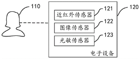
FIG. 1 is an exemplary scene diagram of the application of the in-vivo detection method proposed by the present disclosure
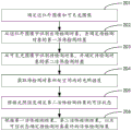
Fig. 2 is a schematic flow chart of a living body detection method according to an exemplary embodiment of the disclosure.
FIG. 3 is a schematic diagram of the logic for implementing the in-vivo detection method proposed by the present disclosure.
Fig. 4 is a schematic flow chart of a living body detection method according to another exemplary embodiment of the disclosure.
Fig. 5 is a flowchart illustrating a living body detection method according to still another exemplary embodiment of the present disclosure.
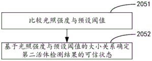
Fig. 6 is a flowchart illustrating a living body detection method according to still another exemplary embodiment of the present disclosure.
Fig. 7 is a flowchart illustrating a living body detection method according to still another exemplary embodiment of the present disclosure.
FIG. 8 is a schematic diagram of a biopsy device provided in an exemplary embodiment of the present disclosure.
Fig. 9 is a schematic view of a living body detecting device according to another exemplary embodiment of the present disclosure.
Fig. 10 is a schematic view of a living body detecting device according to still another exemplary embodiment of the present disclosure.
Fig. 11 is a block diagram of an electronic device provided in an exemplary embodiment of the present disclosure.
Detailed Description
Hereinafter, example embodiments according to the present disclosure will be described in detail with reference to the accompanying drawings. It is to be understood that the described embodiments are merely a subset of the embodiments of the present disclosure and not all embodiments of the present disclosure, with the understanding that the present disclosure is not limited to the example embodiments described herein.
It should be noted that: the relative arrangement of the components and steps, the numerical expressions, and numerical values set forth in these embodiments do not limit the scope of the present disclosure unless specifically stated otherwise.
It will be understood by those of skill in the art that the terms "first," "second," and the like in the embodiments of the present disclosure are used merely to distinguish one element from another, and are not intended to imply any particular technical meaning, nor is the necessary logical order between them.
It is also understood that in embodiments of the present disclosure, "a plurality" may refer to two or more and "at least one" may refer to one, two or more.
It is also to be understood that any reference to any component, data, or structure in the embodiments of the disclosure, may be generally understood as one or more, unless explicitly defined otherwise or stated otherwise.
In addition, the term "and/or" in the present disclosure is only one kind of association relationship describing an associated object, and means that three kinds of relationships may exist, for example, a and/or B may mean: a exists alone, A and B exist simultaneously, and B exists alone. In addition, the character "/" in the present disclosure generally indicates that the former and latter associated objects are in an "or" relationship.
It should also be understood that the description of the various embodiments of the present disclosure emphasizes the differences between the various embodiments, and the same or similar parts may be referred to each other, so that the descriptions thereof are omitted for brevity.
Meanwhile, it should be understood that the sizes of the respective portions shown in the drawings are not drawn in an actual proportional relationship for the convenience of description.
The following description of at least one exemplary embodiment is merely illustrative in nature and is in no way intended to limit the disclosure, its application, or uses.
Techniques, methods, and apparatus known to those of ordinary skill in the relevant art may not be discussed in detail but are intended to be part of the specification where appropriate.
It should be noted that: like reference numbers and letters refer to like items in the following figures, and thus, once an item is defined in one figure, further discussion thereof is not required in subsequent figures.
The disclosed embodiments may be applied to electronic devices such as terminal devices, computer systems, servers, etc., which are operational with numerous other general purpose or special purpose computing system environments or configurations. Examples of well known terminal devices, computing systems, environments, and/or configurations that may be suitable for use with electronic devices, such as terminal devices, computer systems, servers, and the like, include, but are not limited to: personal computer systems, server computer systems, thin clients, thick clients, hand-held or laptop devices, microprocessor-based systems, set top boxes, programmable consumer electronics, network pcs, minicomputer systems, mainframe computer systems, distributed cloud computing environments that include any of the above systems, and the like.
Electronic devices such as terminal devices, computer systems, servers, etc. may be described in the general context of computer system-executable instructions, such as program modules, being executed by a computer system. Generally, program modules may include routines, programs, objects, components, logic, data structures, etc. that perform particular tasks or implement particular abstract data types. The computer system/server may be practiced in distributed cloud computing environments where tasks are performed by remote processing devices that are linked through a communications network. In a distributed cloud computing environment, program modules may be located in both local and remote computer system storage media including memory storage devices.
Summary of the application
In the process of implementing the present disclosure, the inventor finds that, when the final in-vivo detection result of the object to be detected is determined by integrating the in-vivo detection results of the near-infrared image and the visible light image, because the imaging effect of the visible light image is poor in a scene with weak illumination, the in-vivo detection result of the visible light image is likely to be inaccurate, and further, the final in-vivo detection result of the object to be detected is likely to be inaccurate.
Exemplary System
Fig. 1 is an exemplary scene diagram of the application of the living body detection method proposed by the present disclosure.
As shown in fig. 1, the exemplary scene includes an object 110 to be detected and an electronic device 120.
As one example, the electronic device 120 has a near infrared sensor 121, an image sensor 122, and a photosensitive sensor 123 thereon. The near-infrared sensor 121 is configured to acquire a near-infrared image of the object 110 to be detected, the image sensor 122 is configured to acquire a visible light image of the object 110 to be detected, and the photosensitive sensor 123 is configured to detect an illumination intensity in a space where the object 110 to be detected is located.
As an example, the electronic device 120 further has an infrared fill light (not shown in fig. 1) thereon, so that the near-infrared sensor 121 can stably image under various lighting conditions.
It should be noted that, in addition to the above-described components, other components, such as a processor, a memory, and the like, may be included in the electronic device 120, and this disclosure is not illustrated in detail.
In application, when the electronic device 120 receives a living body detection instruction triggered by a user, the near-infrared sensor 121 and the image sensor 122 may be controlled to respectively acquire a near-infrared image and a visible light image of the object 110 to be detected, and the photosensitive sensor 123 is controlled to detect the illumination intensity in the space where the object 110 to be detected is located, and then, based on the living body detection method provided by the present disclosure, whether the object 110 to be detected is a living body is detected.
As to how the electronic device 120 performs the living body detection method provided by the present disclosure, it is described below and will not be described in detail here.
Exemplary method
Fig. 2 is a schematic flow chart of a living body detection method according to an exemplary embodiment of the disclosure. The present embodiment can be applied to an electronic device, such as the electronic device 120 illustrated in fig. 1, as shown in fig. 2, and includes the following steps:
In an embodiment, the near-infrared image may be input to a trained near-infrared image recognition model to recognize the object to be detected in the near-infrared image and obtain a living body detection result (hereinafter, referred to as a first living body detection result for convenience of description) of the object to be detected. The object to be detected may be a living human face, or may be a human face image displayed on a setting medium (e.g., a paper photo, an electronic display screen).
As can be understood by those skilled in the art, if the object to be detected is a living human face, the first living detection result in an ideal case indicates that the object to be detected is a living body; if the object to be detected is a face image, the first living body detection result in an ideal case indicates that the object to be detected is a non-living body.
And step 203, identifying the object to be detected from the visible light image, and determining a second living body detection result of the object to be detected.
In an embodiment, the visible light image may be input to a trained visible light image recognition model to recognize the object to be detected in the visible light image and obtain a living body detection result of the object to be detected (hereinafter, referred to as a second living body detection result for convenience of description).
As can be understood by those skilled in the art, if the object to be detected is a living human face, the second living detection result in an ideal case indicates that the object to be detected is a living body; if the object to be detected is a face image, the second living body detection result in an ideal case indicates that the object to be detected is a non-living body.
Step 204: and acquiring the illumination intensity of the space where the object to be detected is located.
Taking the application scenario illustrated in fig. 1 as an example, the electronic device 120 may obtain the illumination intensity in the space where the object 110 to be detected is located through the photosensitive sensor 123.
Step 205: and determining the credible state of the second living body detection result according to the illumination intensity.
In an embodiment, since the illumination intensity in the space where the object to be detected is located directly affects the imaging effect of the visible light image, and the imaging effect of the visible light image directly affects the second in-vivo detection result, in this step, the confidence state of the second in-vivo detection result can be determined according to the illumination intensity. The trusted state may be trusted or untrusted, among others.
In an embodiment, since the image sensor can automatically adjust the imaging effect of the visible light image in the strong light scene under a normal condition, the in-vivo detection result corresponding to the visible light image collected in the strong light scene is more reliable than the in-vivo detection result corresponding to the visible light image collected in the weak light scene. Based on this, when the illumination intensity in the space where the object to be detected is located is weak, the second living body detection result can be considered to be unreliable, and otherwise, the second living body detection result can be considered to be reliable.
Step 206: and determining the final in-vivo detection result of the object to be detected according to the first in-vivo detection result, the second in-vivo detection result and the credible state.
Based on the embodiment, the object to be detected is identified from the near infrared image, the first living body detection result of the object to be detected is determined, the object to be detected is identified from the visible light image, the second living body detection result of the object to be detected is determined, the illumination intensity in the space where the object to be detected is located is obtained, the credibility state of the second living body detection result is determined according to the illumination intensity, the final living body detection result of the object to be detected is determined according to the first living body detection result, the second living body detection result and the credibility state, and when the final living body detection result of the object to be detected is determined, the living body detection result refers to the illumination intensity in the space where the object to be detected is located, so that the final living body detection result of the object to be detected can be prevented from being influenced due to poor imaging effect of the visible light image in a scene with weak illumination intensity, and the final living body detection result of the object to be detected can be And (6) measuring the result.
In an embodiment, the determining, in step 206, a final in-vivo detection result of the object to be detected according to the first in-vivo detection result, the second in-vivo detection result, and the confidence state includes:
if the first living body detection result indicates that the object to be detected is a non-living body, determining the first living body detection result as a final living body detection result of the object to be detected; if the first living body detection result shows that the object to be detected is a living body and the credibility state shows that the second living body detection result is not credible, determining the first living body detection result as a final living body detection result of the object to be detected; and if the first living body detection result shows that the object to be detected is a living body and the credibility state shows that the second living body detection result is credible, determining the final living body detection result of the object to be detected according to the second living body detection result.
In an embodiment, if the first living body detection result indicates that the object to be detected is a living body and the confidence state indicates that the second living body detection result is confidence, determining the final living body detection result of the object to be detected according to the second living body detection result includes: and if the second living body detection result shows that the object to be detected is a non-living body, determining that the final living body detection result of the object to be detected is the non-living body, and if the second living body detection result shows that the object to be detected is the living body, determining that the final living body detection result of the object to be detected is the living body.
In the above embodiment, since the near-infrared image is more advantageous in the live body detection than the visible light image, when the first live body detection result that the object to be detected is a non-live body is obtained according to the near-infrared image, the first live body detection result can be directly determined as the final live body detection result of the object to be detected, that is, the object to be detected can be directly determined as the non-live body. And when the first living body detection result that the object to be detected is the living body is obtained according to the near-infrared image, the final living body detection result of the object to be detected can be determined by referring to the credible state of the second living body detection result.
To facilitate understanding of the above embodiments, fig. 3 is shown to schematically illustrate the implementation logic of the above step 206, and to show the following application scenarios:
assuming that a user uses a smart phone to perform living body detection on a face on a paper photo, according to the above embodiment provided by the present disclosure, the smart phone may collect a near-infrared image and a visible light image of the face on the paper photo, and obtain an illumination intensity of a space where the paper photo is located, further, the smart phone determines a first living body detection result of the face according to the near-infrared image, determines a second living body detection result of the face according to the visible light image, and determines a trusted status of the second living body detection result according to the illumination intensity.
Assuming that the first living body detection result indicates that the face is an inanimate body, assuming that the second living body detection result indicates that the face is a living body, and assuming that the face is currently in a low-light scene, since the face is currently in the low-light scene, it can be determined that the second living body detection result is not authentic, at this time, the first living body detection result can be determined as a final living body detection result of the face, that is, the face is determined to be an inanimate body.
Assuming that the first living body detection result indicates that the face is a non-living body, and assuming that the second living body detection result indicates that the face is a living body, and assuming that the face is currently in a non-weak light scene, since the face is currently in a non-weak light scene, it can be determined that the second living body detection result is reliable, at this time, the first living body detection result and the second living body detection result can be integrated to determine a final living body detection result of the face, and the final living body detection result indicates that the face is a non-living body.
Based on the embodiment, when the final in-vivo detection result of the object to be detected is judged, the in-vivo detection result refers to the reliability of the second in-vivo detection result of the visible light image, so that the influence on the final in-vivo detection result of the object to be detected due to poor imaging effect of the visible light image in a scene with weak illumination intensity can be avoided, and the final in-vivo detection result of the object to be detected can be accurately judged in various illumination environments; meanwhile, when the first in-vivo detection result shows that the object to be detected is a non-in-vivo object, the first in-vivo detection result is directly determined as the final in-vivo detection result of the object to be detected, so that the advantages of the near-infrared image in-vivo detection are fully exerted, and the detection of the visible light image can be avoided, so that the calculation resource can be saved to a certain extent.
In an embodiment, the number of the near-infrared images and the number of the visible light images determined in step 201 may be one. Taking the application scenario shown in fig. 1 as an example, the electronic device 120 may control the near-infrared sensor 121 and the image sensor 122 to respectively acquire a near-infrared image and a visible light image at the same time point.
In an embodiment, the number of the near-infrared images and the number of the visible light images determined in step 201 may be multiple. Taking the application scenario shown in fig. 1 as an example, the electronic device 120 may control the near-infrared sensor 121 and the image sensor 122 to respectively capture a set of near-infrared images and a set of visible light images at the same time period.
It should be noted that, the specific manner of determining the near-infrared image and the visible light image by the electronic device 120 in step 201 may be limited by the hardware condition of the electronic device 120, and specifically, if the near-infrared sensor 121 and the image sensor 122 on the electronic device 120 can synchronously acquire the near-infrared image and the visible light image, the electronic device 120 may control the near-infrared sensor 121 and the image sensor 122 to respectively acquire a near-infrared image and a visible light image at the same time point when performing the living body detection; if the near-infrared sensor 121 and the image sensor 122 on the electronic device 120 cannot synchronously acquire the near-infrared image and the visible light image, the electronic device 120 may control the near-infrared sensor 121 and the image sensor 122 to respectively acquire a set of near-infrared image and a set of visible light image in the same time period when performing the living body detection, for example, the electronic device 120 may control the near-infrared sensor 121 to acquire 6 near-infrared images in a time period, and control the image sensor 122 to acquire 5 visible light images in the time period.
In an embodiment, as shown in fig. 4, based on the number of the near-infrared images and the visible light images determined in step 201 being multiple, step 202 may include the following steps:
step 2021: and identifying the object to be detected from the near-infrared image aiming at each near-infrared image acquired by the near-infrared sensor, and determining a third living body detection result of the object to be detected according to the near-infrared image.
Similar to the above step 202, in this step 2021, for each near-infrared image acquired by the near-infrared sensor, the near-infrared image may be input to a trained near-infrared image recognition model to recognize the object to be detected in the near-infrared image, and obtain a living body detection result of the object to be detected (hereinafter, referred to as a third living body detection result for convenience of description).
Step 2022: and determining a first living body detection result of the object to be detected according to the third living body detection results corresponding to all the near-infrared images acquired by the near-infrared sensor.
In an embodiment, the first in-vivo detection result of the object to be detected may be determined according to a ratio value between the number of the third in-vivo detection results indicating that the object to be detected is a living body and the total number of the third in-vivo detection results.
In an embodiment, if the ratio value reaches a preset ratio threshold value, for example, 50%, it may be determined that the first in-vivo detection result of the object to be detected indicates that the object to be detected is a living body, and conversely, it may be determined that the first in-vivo detection result of the object to be detected indicates that the object to be detected is a non-living body.
Similarly, in an embodiment, as shown in fig. 5, on the basis that the number of the near-infrared images and the visible light images determined in step 201 is multiple, step 203 may include the following steps:
step 2031: and identifying the object to be detected from the visible light images aiming at each visible light image acquired by the image sensor, and determining a fourth living body detection result of the object to be detected according to the visible light images.
Similar to step 203 described above, in this step 2031, for each visible light image collected by the image sensor, the visible light image may be input to a trained visible light image recognition model to recognize the object to be detected in the visible light image, and obtain a living body detection result of the object to be detected (hereinafter, referred to as a fourth living body detection result for convenience of description).
Step 2032: and determining a second living body detection result of the object to be detected according to the fourth living body detection results corresponding to all the visible light images acquired by the visible light sensor.
In an embodiment, the second in-vivo detection result of the object to be detected may be determined according to a ratio value between the number of the fourth in-vivo detection results indicating that the object to be detected is a living body and the total number of the fourth in-vivo detection results.
In an embodiment, if the ratio value reaches a preset ratio threshold value, for example, 50%, it may be determined that the second in-vivo detection result of the object to be detected indicates that the object to be detected is a living body, and conversely, it may be determined that the second in-vivo detection result of the object to be detected indicates that the object to be detected is a non-living body.
Based on the embodiment, under the condition that the near-infrared image and the visible light image cannot be synchronously acquired by the near-infrared sensor and the image sensor on the electronic equipment, the near-infrared sensor and the image sensor are controlled to respectively acquire the group of near-infrared images and the group of visible light images in the same time period, the living body detection results of the group of near-infrared images are integrated to determine the first living body detection result, and the living body detection results of the group of visible light images are integrated to determine the second living body detection result, so that the final living body detection result of the object to be detected can be accurately determined under various hardware conditions.
As shown in fig. 6, based on the embodiment shown in fig. 2, step 205 may include the following steps:
step 2051: and comparing the illumination intensity with a preset threshold value.
Step 2052: and determining the credibility state of the second living body detection result based on the magnitude relation between the illumination intensity and the preset threshold value.
in one embodiment, a preset threshold may be preset. Based on this, in step 2051, the illumination intensity may be compared with the preset threshold, and if the illumination intensity is smaller than the preset threshold in comparison, in step 2052, it may be determined that the illumination intensity in the space where the object to be detected is located is weak, and then it may be determined that the imaging effect of the visible light image is poor, and the second living body detection result obtained based on the visible light image is also unreliable. On the contrary, if the comparison shows that the illumination intensity is not less than the preset threshold, it may be determined in step 2052 that the second living body detection result is authentic.
Based on the embodiment, the illumination intensity is compared with the preset threshold value, the credible state of the second living body detection result is determined based on the size relation between the illumination intensity and the preset threshold value, the credible state of the second living body detection result is determined according to the imaging effect of the visible light image, and the illumination of the environment where the user is located is referred to, so that the accuracy of the second living body detection result can be greatly improved.
As shown in fig. 7, based on the embodiment shown in fig. 2, step 204 may include the following steps:
step 2041: and determining the opening states of the near infrared sensor and the image sensor.
Step 2042: and if the opening state indicates that the near infrared sensor and the image sensor are both in working states, controlling the photosensitive sensor to detect the illumination intensity in the space where the object to be detected is located.
in an embodiment, the opening states of the near-infrared sensor and the image sensor may be determined first, and if the opening states indicate that the near-infrared sensor and the image sensor are both in the working state, the photosensitive sensor is controlled to detect the illumination intensity in the space where the object to be detected is located, so as to determine the credible state of the second living body detection result according to the detected illumination intensity subsequently.
In addition, if the on state indicates that the near-infrared sensor is in the working state and the image sensor is in the non-working state, the visible light image of the object to be detected cannot be obtained, the second living body detection result cannot be obtained, and further the illumination intensity in the space where the object to be detected is located does not need to be obtained.
If the opening state indicates that the near-infrared sensor is in a non-working state and the image sensor is in a working state, the final living body detection result of the object to be detected can be determined only according to the visible light image, at the moment, the credible state of the second living body detection result does not need to be determined, and further, the illumination intensity in the space where the object to be detected is located does not need to be obtained.
To facilitate understanding of the above embodiments, on the basis of the scenario shown in fig. 1, the following application scenario is shown:
in fig. 1, it is assumed that the image sensor 122 on the electronic device 120 is configured to be in an operating state at 6 o 'clock to 18 o' clock each day, and in other time periods, i.e., 18 o 'clock to 24 o' clock, and 0 o 'clock to 6 o' clock, and it is assumed that the near-infrared sensor 121 on the electronic device 120 is configured to be always in an operating state, then, when the electronic device 120 performs living body detection at any time in the time period of 6 o 'clock to 18 o' clock, the controllable photosensitive sensor 123 obtains the illumination intensity in the space where the object to be detected is located, and when the electronic device performs living body detection at any time in the time period of 18 o 'clock to 24 o' clock, and 0 o 'clock to 6 o' clock, the controllable photosensitive sensor 123 is also in.
Based on the embodiment, the on states of the near infrared sensor and the image sensor are determined, and when the on states indicate that the near infrared sensor and the image sensor are both in working states, the photosensitive sensor is controlled to detect the illumination intensity in the space where the object to be detected is located, so that the working states of the photosensitive sensor can be controlled as required, and resource waste is avoided.
Any of the liveness detection methods provided by the embodiments of the present disclosure may be performed by any suitable device having data processing capabilities, including but not limited to: terminal equipment, a server and the like. Alternatively, any of the liveness detection methods provided by the embodiments of the present disclosure may be executed by a processor, such as the processor executing any of the liveness detection methods mentioned by the embodiments of the present disclosure by calling corresponding instructions stored in a memory. And will not be described in detail below.
Exemplary devices
FIG. 8 is a schematic diagram of a biopsy device provided in an exemplary embodiment of the present disclosure. The present embodiment can be applied to an electronic device, such as the electronic device 120 illustrated in fig. 1, as shown in fig. 8, and includes:
an image determining module 81 for determining a near-infrared image and a visible light image;
a first detection module 82, configured to identify an object to be detected from the near-infrared image determined by the image determination module 81, and determine a first living body detection result of the object to be detected;
the second detection module 83 is configured to identify the object to be detected from the visible light image determined by the image determination module 81, and determine a second living body detection result of the object to be detected;
an illumination obtaining module 84, configured to obtain illumination intensity in a space where the object to be detected is located;
a state determining module 85, configured to determine a trusted state of the second living body detection result according to the illumination intensity acquired by the illumination acquiring module 84;
a result determining module 86, configured to determine a final in-vivo detection result of the object to be detected according to the first in-vivo detection result determined by the first detecting module 82, the second in-vivo detection result determined by the second detecting module 83, and the confidence state determined by the state determining module 65.
In an embodiment, the result determining module 86 is specifically configured to:
if the first living body detection result determined by the first detection module 82 indicates that the object to be detected is a non-living body, determining the first living body detection result as a final living body detection result of the object to be detected;
if the first living body detection result determined by the first detection module 82 indicates that the object to be detected is a living body and the credible state determined by the state determination module 85 indicates that the second living body detection result determined by the second detection module 83 is not credible, determining the first living body detection result as a final living body detection result of the object to be detected;
if the first living body detection result determined by the first detection module 82 indicates that the object to be detected is a living body and the trusted state determined by the state determination module 85 indicates that the second living body detection result determined by the second detection module 83 is trusted, determining a final living body detection result of the object to be detected according to the second living body detection result.
In an embodiment, the result determining module 86 is specifically configured to:
if the second living body detection result determined by the second detection module 83 indicates that the object to be detected is a non-living body, determining that the final living body detection result of the object to be detected is the non-living body;
if the second living body detection result determined by the second detection module 83 indicates that the object to be detected is a living body, determining that the final living body detection result of the object to be detected is a living body.
In an embodiment, the image determining module 81 is specifically configured to:
and controlling the near-infrared sensor and the image sensor to respectively acquire a near-infrared image and a visible light image at the same time point.
In an embodiment, the image determining module 81 is specifically configured to:
and controlling the near-infrared sensor and the image sensor to respectively acquire a group of near-infrared images and a group of visible light images in the same time period.
As shown in fig. 9, on the basis of the embodiment shown in fig. 8, the first detecting module 82 includes:
the first detection submodule 821 is configured to identify, for each near-infrared image acquired by the near-infrared sensor, an object to be detected from the near-infrared image, and determine a third living body detection result of the object to be detected according to the near-infrared image;
the first determining submodule 822 is configured to determine a first living body detection result of the object to be detected according to third living body detection results corresponding to all near-infrared images acquired by the near-infrared sensor.
The second detection module 83 includes:
the second detection submodule 831 is configured to, for each visible light image acquired by the image sensor, identify an object to be detected from the visible light image, and determine a fourth living body detection result of the object to be detected according to the visible light image;
the second determining submodule 832 is configured to determine a second in-vivo detection result of the object to be detected according to fourth in-vivo detection results corresponding to all the visible light images acquired by the visible light sensor.
As shown in fig. 10, on the basis of the embodiment shown in fig. 8, the state determining module 85 includes:
a comparison submodule 851 for comparing the illumination intensity with a preset threshold;
a third determining sub-module 852, configured to determine a trusted status of the second living body detection result based on a magnitude relationship between the illumination intensity determined by the comparing sub-module 851 and a preset threshold.
The illumination acquisition module 84 includes:
a fourth determining submodule 841 for determining the on-state of the near-infrared sensor and the image sensor;
the control sub-module 842 is configured to control the photosensor to detect the illumination intensity in the space where the object to be detected is located if the on state determined by the second determining sub-module 841 indicates that the near-infrared sensor and the image sensor are both in the working state.
Exemplary electronic device
Next, an electronic apparatus according to an embodiment of the present disclosure is described with reference to fig. 11. The electronic device may be either or both of the first device 100 and the second device 200, or a stand-alone device separate from them that may communicate with the first device and the second device to receive the collected input signals therefrom.
FIG. 11 illustrates a block diagram of an electronic device in accordance with an embodiment of the disclosure.
As shown in fig. 11, electronic device 110 includes one or more processors 111 and memory 112.
Processor 111 may be a Central Processing Unit (CPU) or other form of processing unit having data processing capabilities and/or instruction execution capabilities, and may control other components in electronic device 110 to perform desired functions.
Memory 112 may include one or more computer program products that may include various forms of computer-readable storage media, such as volatile memory and/or non-volatile memory. The volatile memory may include, for example, Random Access Memory (RAM), cache memory (cache), and/or the like. The non-volatile memory may include, for example, Read Only Memory (ROM), hard disk, flash memory, etc. One or more computer program instructions may be stored on the computer-readable storage medium and executed by processor 111 to implement the above-described liveness detection methods of the various embodiments of the present disclosure and/or other desired functions. Various contents such as an input signal, a signal component, a noise component, etc. may also be stored in the computer-readable storage medium.
In one example, the electronic device 110 may further include: an input device 113 and an output device 114, which are interconnected by a bus system and/or other form of connection mechanism (not shown).
For example, when the electronic device is the first device 100 or the second device 200, the input device 113 may be a microphone or a microphone array as described above for capturing an input signal of a sound source. When the electronic device is a stand-alone device, the input means 113 may be a communication network connector for receiving the acquired input signals from the first device 100 and the second device 200.
The input device 113 may also include, for example, a keyboard, a mouse, and the like.
The output device 114 may output various information including the determined distance information, direction information, and the like to the outside. The output devices 114 may include, for example, a display, speakers, a printer, and a communication network and remote output devices connected thereto, among others.
Of course, for simplicity, only some of the components of the electronic device 110 relevant to the present disclosure are shown in fig. 11, omitting components such as buses, input/output interfaces, and the like. In addition, electronic device 110 may include any other suitable components, depending on the particular application.
Exemplary computer program product and computer-readable storage Medium
In addition to the above-described methods and apparatus, embodiments of the present disclosure may also be a computer program product comprising computer program instructions that, when executed by a processor, cause the processor to perform the steps in the liveness detection method according to various embodiments of the present disclosure described in the "exemplary methods" section above of this specification.
The computer program product may write program code for carrying out operations for embodiments of the present disclosure in any combination of one or more programming languages, including an object oriented programming language such as Java, C + + or the like and conventional procedural programming languages, such as the "C" programming language or similar programming languages. The program code may execute entirely on the user's computing device, partly on the user's device, as a stand-alone software package, partly on the user's computing device and partly on a remote computing device, or entirely on the remote computing device or server.
Furthermore, embodiments of the present disclosure may also be a computer-readable storage medium having stored thereon computer program instructions that, when executed by a processor, cause the processor to perform the steps in the liveness detection method according to various embodiments of the present disclosure described in the "exemplary methods" section above in this specification.
The computer-readable storage medium may take any combination of one or more readable media. The readable medium may be a readable signal medium or a readable storage medium. A readable storage medium may include, for example, but not limited to, an electronic, magnetic, optical, electromagnetic, infrared, or semiconductor system, apparatus, or device, or a combination of any of the foregoing. More specific examples (a non-exhaustive list) of the readable storage medium include: an electrical connection having one or more wires, a portable disk, a hard disk, a Random Access Memory (RAM), a read-only memory (ROM), an erasable programmable read-only memory (EPROM or flash memory), an optical fiber, a portable compact disc read-only memory (CD-ROM), an optical storage device, a magnetic storage device, or any suitable combination of the foregoing.
The foregoing describes the general principles of the present disclosure in conjunction with specific embodiments, however, it is noted that the advantages, effects, etc. mentioned in the present disclosure are merely examples and are not limiting, and they should not be considered essential to the various embodiments of the present disclosure. Furthermore, the foregoing disclosure of specific details is for the purpose of illustration and description and is not intended to be limiting, since the disclosure is not intended to be limited to the specific details so described.
In the present specification, the embodiments are described in a progressive manner, each embodiment focuses on differences from other embodiments, and the same or similar parts in the embodiments are referred to each other. For the system embodiment, since it basically corresponds to the method embodiment, the description is relatively simple, and for the relevant points, reference may be made to the partial description of the method embodiment.
The block diagrams of devices, apparatuses, systems referred to in this disclosure are only given as illustrative examples and are not intended to require or imply that the connections, arrangements, configurations, etc. must be made in the manner shown in the block diagrams. These devices, apparatuses, devices, systems may be connected, arranged, configured in any manner, as will be appreciated by those skilled in the art. Words such as "including," "comprising," "having," and the like are open-ended words that mean "including, but not limited to," and are used interchangeably therewith. The words "or" and "as used herein mean, and are used interchangeably with, the word" and/or, "unless the context clearly dictates otherwise. The word "such as" is used herein to mean, and is used interchangeably with, the phrase "such as but not limited to".
The methods and apparatus of the present disclosure may be implemented in a number of ways. For example, the methods and apparatus of the present disclosure may be implemented by software, hardware, firmware, or any combination of software, hardware, and firmware. The above-described order for the steps of the method is for illustration only, and the steps of the method of the present disclosure are not limited to the order specifically described above unless specifically stated otherwise. Further, in some embodiments, the present disclosure may also be embodied as programs recorded in a recording medium, the programs including machine-readable instructions for implementing the methods according to the present disclosure. Thus, the present disclosure also covers a recording medium storing a program for executing the method according to the present disclosure.
It is also noted that in the devices, apparatuses, and methods of the present disclosure, each component or step can be decomposed and/or recombined. These decompositions and/or recombinations are to be considered equivalents of the present disclosure.
The previous description of the disclosed aspects is provided to enable any person skilled in the art to make or use the present disclosure. Various modifications to these aspects will be readily apparent to those skilled in the art, and the generic principles defined herein may be applied to other aspects without departing from the scope of the disclosure. Thus, the present disclosure is not intended to be limited to the aspects shown herein but is to be accorded the widest scope consistent with the principles and novel features disclosed herein.
The foregoing description has been presented for purposes of illustration and description. Furthermore, this description is not intended to limit embodiments of the disclosure to the form disclosed herein. While a number of example aspects and embodiments have been discussed above, those of skill in the art will recognize certain variations, modifications, alterations, additions and sub-combinations thereof.
Claims (10)
1. A method of in vivo detection comprising:
determining a near-infrared image and a visible light image;
identifying an object to be detected from the near-infrared image, and determining a first living body detection result of the object to be detected;
identifying the object to be detected from the visible light image, and determining a second living body detection result of the object to be detected;
acquiring the illumination intensity of the space where the object to be detected is located;
determining the credible state of the second living body detection result according to the illumination intensity;
and determining the final in-vivo detection result of the object to be detected according to the first in-vivo detection result, the second in-vivo detection result and the credible state.
2. The method according to claim 1, wherein the determining a final in-vivo detection result of the object to be detected according to the first in-vivo detection result, the second in-vivo detection result, and the confidence state comprises:
if the first in-vivo detection result indicates that the object to be detected is a non-in-vivo object, determining the first in-vivo detection result as a final in-vivo detection result of the object to be detected;
if the first living body detection result shows that the object to be detected is a living body and the credibility state shows that the second living body detection result is not credible, determining the first living body detection result as a final living body detection result of the object to be detected;
and if the first living body detection result shows that the object to be detected is a living body and the credibility state shows that the second living body detection result is credible, determining the final living body detection result of the object to be detected according to the second living body detection result.
3. The method of claim 1, wherein the determining the trustworthy state of the second liveness detection result from the illumination intensity comprises:
comparing the illumination intensity with a preset threshold value;
and determining the credible state of the second living body detection result based on the magnitude relation between the illumination intensity and a preset threshold value.
4. The method according to claim 2, wherein the determining a final in-vivo detection result of the object to be detected according to the second in-vivo detection result comprises:
if the second living body detection result shows that the object to be detected is a non-living body, determining that the final living body detection result of the object to be detected is the non-living body;
and if the second living body detection result shows that the object to be detected is a living body, determining that the final living body detection result of the object to be detected is the living body.
5. The method of claim 1, wherein the determining a near-infrared image and a visible light image comprises:
and controlling the near-infrared sensor and the image sensor to respectively acquire a near-infrared image and a visible light image at the same time point.
6. The method of claim 1, wherein the determining a near-infrared image and a visible light image comprises:
and controlling the near-infrared sensor and the image sensor to respectively acquire a group of near-infrared images and a group of visible light images in the same time period.
7. The method of claim 6, wherein the identifying the object to be detected from the near-infrared image and determining a first in-vivo detection result of the object to be detected comprises:
identifying an object to be detected from each near-infrared image acquired by the near-infrared sensor, and determining a third living body detection result of the object to be detected according to the near-infrared image;
and determining a first living body detection result of the object to be detected according to the third living body detection results corresponding to all the near-infrared images acquired by the near-infrared sensor.
8. A living body detection apparatus comprising:
the image determining module is used for determining a near infrared image and a visible light image;
the first detection module is used for identifying the object to be detected from the near-infrared image determined by the image determination module and determining a first living body detection result of the object to be detected;
the second detection module is used for identifying the object to be detected from the visible light image determined by the image determination module and determining a second living body detection result of the object to be detected;
the illumination acquisition module is used for acquiring the illumination intensity in the space where the object to be detected is located;
the state determining module is used for determining the credible state of the second living body detection result according to the illumination intensity acquired by the illumination acquiring module;
and the result determining module is used for determining the final in-vivo detection result of the object to be detected according to the first in-vivo detection result determined by the first detecting module, the second in-vivo detection result determined by the second detecting module and the credible state determined by the state determining module.
9. A computer-readable storage medium storing a computer program for executing the living body detecting method according to any one of claims 1 to 7.
10. An electronic device, the electronic device comprising:
a processor;
a memory for storing the processor-executable instructions;
the processor for performing the in-vivo detection method of any one of claims 1 to 7.
Priority Applications (1)
| Application Number | Priority Date | Filing Date | Title |
|---|---|---|---|
| CN202011162151.9A CN112364724B (en) | 2020-10-27 | 2020-10-27 | Living body detection method and device, storage medium and electronic equipment |
Applications Claiming Priority (1)
| Application Number | Priority Date | Filing Date | Title |
|---|---|---|---|
| CN202011162151.9A CN112364724B (en) | 2020-10-27 | 2020-10-27 | Living body detection method and device, storage medium and electronic equipment |
Publications (2)
| Publication Number | Publication Date |
|---|---|
| CN112364724A true CN112364724A (en) | 2021-02-12 |
| CN112364724B CN112364724B (en) | 2024-08-06 |
Family
ID=74512149
Family Applications (1)
| Application Number | Title | Priority Date | Filing Date |
|---|---|---|---|
| CN202011162151.9A Active CN112364724B (en) | 2020-10-27 | 2020-10-27 | Living body detection method and device, storage medium and electronic equipment |
Country Status (1)
| Country | Link |
|---|---|
| CN (1) | CN112364724B (en) |
Cited By (2)
| Publication number | Priority date | Publication date | Assignee | Title |
|---|---|---|---|---|
| CN113627346A (en) * | 2021-08-11 | 2021-11-09 | 深圳市捷顺科技实业股份有限公司 | Channel gate detection method, device, equipment and readable storage medium |
| CN114550050A (en) * | 2022-02-23 | 2022-05-27 | 重庆紫光华山智安科技有限公司 | Safety belt detection method and system, electronic equipment and readable storage medium |
Citations (4)
| Publication number | Priority date | Publication date | Assignee | Title |
|---|---|---|---|---|
| WO2019056988A1 (en) * | 2017-09-25 | 2019-03-28 | 杭州海康威视数字技术股份有限公司 | Face recognition method and apparatus, and computer device |
| CN109871773A (en) * | 2019-01-21 | 2019-06-11 | 深圳市云眸科技有限公司 | Biopsy method, device and door access machine |
| CN110929566A (en) * | 2019-10-16 | 2020-03-27 | 厦门大学 | Human face living body detection method based on visible light and near-infrared binocular camera |
| WO2020177226A1 (en) * | 2019-03-04 | 2020-09-10 | 平安科技(深圳)有限公司 | Improved resnet-based human face in-vivo detection method and related device |
-
2020
- 2020-10-27 CN CN202011162151.9A patent/CN112364724B/en active Active
Patent Citations (4)
| Publication number | Priority date | Publication date | Assignee | Title |
|---|---|---|---|---|
| WO2019056988A1 (en) * | 2017-09-25 | 2019-03-28 | 杭州海康威视数字技术股份有限公司 | Face recognition method and apparatus, and computer device |
| CN109871773A (en) * | 2019-01-21 | 2019-06-11 | 深圳市云眸科技有限公司 | Biopsy method, device and door access machine |
| WO2020177226A1 (en) * | 2019-03-04 | 2020-09-10 | 平安科技(深圳)有限公司 | Improved resnet-based human face in-vivo detection method and related device |
| CN110929566A (en) * | 2019-10-16 | 2020-03-27 | 厦门大学 | Human face living body detection method based on visible light and near-infrared binocular camera |
Cited By (2)
| Publication number | Priority date | Publication date | Assignee | Title |
|---|---|---|---|---|
| CN113627346A (en) * | 2021-08-11 | 2021-11-09 | 深圳市捷顺科技实业股份有限公司 | Channel gate detection method, device, equipment and readable storage medium |
| CN114550050A (en) * | 2022-02-23 | 2022-05-27 | 重庆紫光华山智安科技有限公司 | Safety belt detection method and system, electronic equipment and readable storage medium |
Also Published As
| Publication number | Publication date |
|---|---|
| CN112364724B (en) | 2024-08-06 |
Similar Documents
| Publication | Publication Date | Title |
|---|---|---|
| US8626782B2 (en) | Pattern identification apparatus and control method thereof | |
| US10111103B2 (en) | Spoof detection using proximity sensors | |
| CN107995982B (en) | Target identification method and device and intelligent terminal | |
| US10261393B2 (en) | Method for controlling infrared illuminator and related image-recording device | |
| US11170520B2 (en) | Image processing apparatus for analyzing an image to detect an object within the image | |
| KR20210012012A (en) | Object tracking methods and apparatuses, electronic devices and storage media | |
| CN110210196B (en) | Identity authentication method and device | |
| CN113610030A (en) | Behavior recognition method and behavior recognition device | |
| US20240404268A1 (en) | Training Models for Object Detection | |
| CN112364724A (en) | Living body detection method and apparatus, storage medium, and electronic device | |
| CN110609977A (en) | Noise floor adjustment processing method, device and computer equipment based on proximity sensor | |
| CN114139630A (en) | Gesture recognition method and device, storage medium and electronic equipment | |
| CN114821066A (en) | Model training method and device, electronic equipment and computer readable storage medium | |
| CN114037978B (en) | Fatigue detection method, device, electronic device and storage medium | |
| US11763561B2 (en) | Information processing apparatus, information processing method, and program | |
| US20190244389A1 (en) | Information processing apparatus, system, method for controlling information processing apparatus, and non-transitory computer readable storage medium | |
| CN112329624A (en) | Liveness detection method and device, storage medium, electronic device | |
| US20180314893A1 (en) | Information processing device, video image monitoring system, information processing method, and recording medium | |
| KR101529384B1 (en) | Subject detection device and subject detection method for detecting subject image from image and storage medium therefor | |
| CN114067386A (en) | Face detection method and device, electronic equipment and computer readable storage medium | |
| CN112991418A (en) | Image depth prediction and neural network training method and device, medium and equipment | |
| CN112200804A (en) | Image detection method and device, computer readable storage medium and electronic equipment | |
| CN108875553A (en) | Method, apparatus, system and the computer storage medium that the testimony of a witness is veritified | |
| CN112770057A (en) | Camera parameter adjusting method and device, electronic equipment and storage medium | |
| US12307819B2 (en) | Identification model generation apparatus, identification apparatus, identification model generation method, identification method, and storage medium |
Legal Events
| Date | Code | Title | Description |
|---|---|---|---|
| PB01 | Publication | ||
| PB01 | Publication | ||
| SE01 | Entry into force of request for substantive examination | ||
| SE01 | Entry into force of request for substantive examination | ||
| GR01 | Patent grant | ||
| GR01 | Patent grant |