Intelligent high-reliability low-voltage power supply and distribution system based on radial wiring and method thereof
Technical Field
The invention relates to the technical field of power supply and distribution, in particular to an application of the power supply and distribution system which is applicable to dispersed load areas of industrial construction sites, auxiliary equipment of power plants, coal mines, steel, petrochemical industry, chemical fibers, chip manufacturing and the like and has high requirements of field equipment and instruments on power supply and distribution quality. In particular to an intelligent high-reliability low-voltage power supply and distribution system based on radial wiring and a method thereof.
Background
At present, low-voltage power supply and distribution lines have basic wiring modes such as a radial type, a branch type, a ring type and the like. The radial wiring is based on independent load or concentrated load and is supplied by independent distribution lines, is characterized in that outgoing lines are not affected when in fault, and is generally used in places with large capacity, concentrated capacity or high power supply reliability of single equipment. Compared with other wiring forms, radial wiring is already higher than other wiring forms. However, for many application scenarios, the conventional low-voltage power supply and distribution system only adopting radial wiring still cannot meet the requirement of load on high-reliability power supply, and the conventional low-voltage power supply and distribution system generally has the problem of low intelligence.
For the monitoring and protecting equipment of the conventional power supply and distribution system, except for the power line, a special communication line needs to be laid between each station and the load, the cost and the engineering complexity are very high, and the expansion and transformation flexibility of the subsequent engineering is limited.
The power supply of the power grid has the conditions of voltage sag and short-time interruption, and the load in the power distribution system is seriously influenced. The voltage sag and the short-term interruption have been well-defined in the national standard "power quality voltage sag and short-term interruption" (GB/T30317). Because the voltage sag and the short-time interruption occur and the recovery speed is very fast, the conventional power supply and distribution system can only be forced to power off, and even if the system is provided with a standby diesel generator, the power-off dead time exists between the power failure of a power supply bus and the completion of the starting of the diesel generator.
Because nonlinear loads and power electronic equipment exist in the power supply and distribution system, harmonic current with the amplitude and frequency changing constantly can be generated, harmonic waves enter a power grid through a power supply bus access point, pollution is caused, and the power grid company fines when the harmonic waves exceed a limit value. The national standard of harmonic wave of electric energy quality public power grid (GB/T14549) clearly defines the harmonic wave and gives the limit value of the harmonic wave injected into the access point of the power grid.
The intelligent microcomputer relay protection device is widely applied to power generation, power transmission and power transformation links of electric power, but is rarely used in power supply and distribution links, so that a low-voltage power supply and distribution system is originally lagged behind. The thermomagnetic tripping circuit breaker fuse is generally used in the conventional power supply and distribution system, particularly in a low-voltage power distribution link, when any load branch breaks down, the whole system is required to be powered off, the removing process is complex, and the workload is large.
Because reactive loss caused by a power line and a load causes too low voltage on a load side, the optimal solution is usually in-situ compensation, and the conventional in-situ compensation adopts large-size capacitance compensation, can only carry out constant value compensation, lacks flexibility and has short operation and maintenance period. When a high-power motor is started under load, reactive loss sudden change can be caused, and the system voltage is greatly reduced. If corresponding measures are not taken during normal operation or when the alternating current motor is directly started, equipment consumes reactive power, and the voltage of a power distribution bus connected with the motor generates large voltage deviation, so that the normal operation of other electric equipment connected to the power distribution bus is directly influenced, and over-voltage and under-voltage protection actions can be triggered to cause harmful tripping of the equipment; meanwhile, the motor winding is heated by overlarge starting impact current, so that the insulation aging is accelerated, and the service life of the motor is influenced. In order to deal with the voltage deviation problem of the distribution bus, the voltage deviation level of the distribution bus caused in the normal operation and the motor starting process is limited on the one hand; on the other hand, improvement measures are taken to reduce the impact caused by the starting of the motor so as to meet the limitation requirement of the bus voltage deviation level. The current relevant specification standards impose a clear limit on the level of deviation of the bus voltage at the start of the ac motor: the bus is connected with lighting or other loads sensitive to voltage fluctuation, and the voltage of the motor is not lower than 90% of the rated voltage when the motor is frequently started; when the motor is started infrequently, the voltage is not lower than 85% of the rated voltage. The voltage fluctuation of the load which is not illuminated or sensitive to other voltage fluctuation on the bus is not lower than 80 percent of the rated voltage. When other electric equipment is not connected to the bus voltage, the starting torque of the motor can be determined according to the condition of ensuring the starting torque of the motor; for low voltage motors, it is also ensured that the voltage of the contactor coil is not lower than the release voltage.
Disclosure of Invention
Therefore, the technical problem to be solved by the invention is as follows:
the low-voltage power supply and distribution system with conventional radial wiring has poor reliability and low intellectualization; besides the power line, a dedicated communication line needs to be laid between each station and the load, so that the cost and the engineering complexity are high; when the power supply bus is abnormal, the whole system is powered off, and even if the standby diesel generator is started, a power-off dead time exists between the power failure of the power supply bus and the starting of diesel; harmonic waves generated in the system enter a power grid through a power supply bus access point, so that pollution is caused, and fine money is paid by a power grid company when the harmonic waves exceed a limit value; when any load branch in the system breaks down, the whole system needs to be powered off, the removal process is complex, and the workload is large; due to reactive loss caused by a power line and a load, the voltage at the load side is too low, and the conventional capacitance compensation has large volume and can only carry out fixed value compensation; when a high-power motor is started under load, reactive loss sudden change can be caused, and the system voltage is greatly reduced.
In order to overcome the defects, the invention discloses an intelligent high-reliability low-voltage power supply and distribution system based on radial wiring and a method thereof by intensively researching and designing and comprehensively engaging in relevant experiences and research achievements for many years.
In order to solve the technical problems, the invention provides the following technical scheme:
an intelligent high-reliability low-voltage power supply and distribution system based on radial wiring comprises main station equipment between a power supply bus and a load bus, and N regional station equipment between the load bus and a load, wherein N is a natural number greater than or equal to 1;
the master station equipment comprises a master station controller, a master station communication coupler, a master station diesel generator, a master station multifunctional power supply, a communication wave trap, a master station power supply bus voltage and current detection module, a grid-connected switch and a human-computer interaction interface; the current output end of the power supply bus is electrically connected with the communication wave trap, the voltage and current detection module of the main station power supply bus, the grid-connected switch and the current input end of the load bus in sequence; the master station communication coupler, the master station diesel generator and the master station multifunctional power supply are respectively and electrically connected with the load bus; the master station controller is respectively in communication connection with the master station communication coupler, the master station diesel generator, the master station multifunctional power supply, the communication wave trap, the master station power supply bus voltage and current detection module, the grid-connected switch and the human-computer interaction interface; the master station multifunctional power supply is also in communication connection with the master station power supply bus voltage and current detection module, the grid-connected switch and the master station diesel generator respectively;
each regional station device comprises a regional voltage and current detector, a regional switch, a regional communication coupler, a regional multifunctional power supply and a regional controller which are arranged between a load bus and a regional load sub-bus, and n branch switches arranged between the regional load sub-bus and a branch load, wherein n is a natural number which is more than or equal to 1; the current output end of the load bus is electrically connected with the current input end of the regional load son-mother line sequentially through the regional voltage and current detector and the regional switch, and the regional multifunctional power supply is electrically connected with the regional load son-mother line; the zone communication coupler is located between the load bus and the zone voltage current detector; the regional load sub-bus is electrically connected with the n branch switches; the zone controller is in electrical communication with the zone voltage current detector, the zone switch, the zone communication coupler, the zone multifunction power supply, and the n branch switches; the regional multifunctional power supply is in communication connection with the regional switch.
In the intelligent high-reliability low-voltage power supply and distribution system based on the radial wiring, the main station controller comprises a coordination control unit layer and a function control unit layer; the coordination control unit layer comprises a master station communication control unit and a master station function coordination control unit; the function control unit layer comprises a power supply bus detection unit, a grid-connected switch control unit, a multifunctional power supply control unit, a diesel generator control unit, a communication wave trap monitoring unit and a communication transceiving control unit; the human-computer interaction interface is in communication connection with the master station communication control unit, and the master station communication control unit is in communication connection with the master station function coordination control unit; the master station function coordination control unit is respectively connected with the diesel generator through the power supply bus detection unit, the grid-connected switch control unit, the multifunctional power supply control unit, the diesel generator control unit, the master station power supply bus voltage and current detection module, the grid-connected switch, the master station multifunctional power supply and the master station diesel generator in a communication mode, and the master station communication control unit is respectively connected with the communication wave trap monitoring unit and the communication transceiving control unit in a communication mode through the communication wave trap and the master station communication coupler.
The intelligent high-reliability low-voltage power supply and distribution system based on radial wiring comprises a main station multifunctional power supply main control unit layer, a main station basic control unit layer and a main station main circuit, wherein the main station basic control unit layer comprises a main station power supply function realization basic control unit and a main station energy storage element management unit, the main circuit comprises a main station soft start switch group K11, a main station converter circuit unit IGBT11 and a main station energy storage element unit BMS11, the main station power supply bus voltage and current detection module, the grid-connected switch, the main station diesel generator and the main station controller are in communication connection with the main station multifunctional power supply main control unit layer, and the main station multifunctional power supply main control unit layer is in communication connection with the main station power supply function realization basic control unit and the main station energy storage element management unit; the master station energy storage element BMS11 is in communication connection with the master station energy storage element management unit; the master station soft start switch group K11 and the master station current transformation circuit unit IGBT11 are in communication connection with the master station power supply function realization basic control unit; the main station energy storage element unit BMS11 is electrically connected with the main station current transformation circuit unit IGBT11, the main station current transformation circuit unit IGBT11 is electrically connected with one end of the main station soft start switch group K11, and the other end of the main station soft start switch group K11 is electrically connected with the load bus; a sampling device CPT11 is arranged between the master station soft start switch group K11 and the master station current transformation circuit unit IGBT11, and a signal output end of the sampling device CPT11 is in communication connection with the basic control unit in the master station power supply function; a sampling device CPT12 is arranged between the main station current transformation circuit unit IGBT11 and the main station energy storage element unit BMS11, and the sampling device CPT12 is respectively in communication connection with the main station power supply function realization basic control unit and the main station energy storage element management unit;
the main station multifunctional power supply is provided with a main power supply mode and an auxiliary power supply mode, and is realized by the cooperation of a main station power supply function realization basic control unit and a main station energy storage element management unit; when the basic control unit is realized by only starting the power supply function of the main station, the mode is an auxiliary power supply mode; the master station controller enables the master station multifunctional power supply to realize automatic mode switching, and the master station multifunctional power supply realizes seamless switching between the power supply bus and the master station diesel generator.
The intelligent high-reliability low-voltage power supply and distribution system based on the radial wiring comprises a grid-connected switch controller and a grid-connected switch circuit, wherein the main station controller and the main station multifunctional power supply are in communication connection with the grid-connected switch controller, and the grid-connected switch circuit is a grid-connected switch K601; one end of the grid-connected switch K601 is electrically connected with the power supply bus, and the other end of the grid-connected switch K601 is electrically connected with the load bus; a sampling device CTP601 is arranged between the grid-connected switch K601 and the power supply bus, a sampling device CPT602 is arranged between the grid-connected switch K601 and the load bus, and the signal output ends of the sampling device CTP601 and the sampling device CPT602 are in communication connection with the input end of the grid-connected switch controller; the grid-connected switch K601 is in communication connection with the grid-connected switch controller;
the master station diesel generator comprises a master station diesel generator controller and a diesel generator control circuit, and the master station controller and the master station multifunctional power supply are in communication connection with the master station diesel generator controller; the diesel generator control circuit comprises a diesel generator and a diesel generator switch K701, the diesel generator is electrically connected with the load bus through the diesel generator switch K701, a sampling device CPT702 is arranged between the diesel generator and the diesel generator switch K701, and the sampling device CPT701 is arranged between the diesel generator switch K701 and the load bus; the diesel generator, the sampling device CPT702, the sampling device CPT701 and the generator switch K701 are respectively in communication connection with the master station diesel generator controller.
The intelligent high-reliability low-voltage power supply and distribution system based on the radial wiring comprises a regional controller, a regional coordination control unit layer and a regional function control unit layer, wherein the regional controller comprises a power supply unit layer, a power supply unit layer and a power distribution unit layer; the regional coordination control unit layer comprises a regional communication control unit and a regional function coordination control unit; the regional function control unit layer comprises a regional detection unit, a regional switch control unit, a regional multifunctional power supply control unit, a branch switch state collection control unit and a communication transceiving control unit; the area communication control unit is in communication connection with the area function coordination control unit; the regional function coordination control unit is in communication connection with the regional voltage and current detector, the regional switch, the regional multifunctional power supply and the n branch switches through the regional detection unit, the regional switch control unit, the regional multifunctional power supply control unit and the branch switch state collection control unit respectively, and the regional communication control unit is in communication connection with the regional communication coupler through the regional communication transceiving control unit.
The regional multifunctional power supply comprises a regional main control unit layer, a regional basic control unit layer and a regional main circuit, wherein the regional basic control unit layer comprises a regional power supply function realization basic control unit and a regional energy storage element management unit, the regional main circuit comprises a regional soft start switch group K21, a regional converter circuit unit IGBT21 and a regional energy storage element unit BMS21, the regional controller is in communication connection with the regional multifunctional power supply main control unit of the regional main control unit layer, and the regional multifunctional power supply main control unit is in communication connection with the regional power supply function realization basic control unit and the regional energy storage element management unit; the regional energy storage element unit BMS21 is in communication connection with the regional energy storage element management unit; the region soft start switch group K21 and the region current transformation circuit unit IGBT21 are in communication connection with the region power supply function realization basic control unit; the regional energy storage element unit BMS21 is electrically connected with the regional converter circuit unit IGBT21, the regional converter circuit unit IGBT21 is electrically connected with one end of the regional soft start switch group K21, and the other end of the regional soft start switch group K21 is electrically connected with the regional load son-son wire; a sampling device CPT21 is arranged between the region soft start switch group K21 and the region current transformation circuit unit IGBT21, and the signal output end of the sampling device CPT21 is in communication connection with the region power supply function realization basic control unit; a sampling device CPT22 is arranged between the area current transformation circuit unit IGBT21 and the area energy storage element unit BMS21, and the sampling device CPT22 is respectively in communication connection with the area power supply function realization basic control unit and the area energy storage element management unit;
the regional multifunctional power supply is provided with a standby power mode and a reactive compensation mode, and is realized by matching a regional power supply function realization basic control unit with a regional energy storage element management unit;
the area switch comprises an area switch controller and an area switch circuit, the area controller and the area multifunctional power supply are in communication connection with the area switch controller, and the area switch circuit is an area switch K501; one end of the area switch K501 is electrically connected with the load bus, and the other end of the area switch K501 is electrically connected with the area load primary-secondary wire; a sampling device CTP501 is arranged between the area switch K501 and the load bus bar, a sampling device CPT502 is arranged between the area switch K501 and the area load sub bus bar, and the signal output ends of the sampling device CTP501 and the sampling device CPT502 are in communication connection with the area switch controller; the area switch K501 is in communication connection with the area switch controller;
the branch switch comprises a branch switch controller and a branch switch circuit, the area controller is in communication connection with the branch switch controller, the branch switch circuit is a branch switch K401, one end of the branch switch K401 is electrically connected with an area load primary and secondary wire, the other end of the branch switch K401 is electrically connected with a branch load, and the branch switch K401 is in communication connection with the branch switch controller.
The intelligent high-reliability low-voltage power supply and distribution method based on the radial wiring comprises the following steps:
(1) installing any one of the intelligent high-reliability low-voltage supply and distribution systems based on the radial wiring to build main station equipment and regional station equipment, and connecting circuit lines and communication lines of the main station equipment and the regional station equipment;
(2) the method comprises the steps that the types, characteristics and parameters of equipment in main station equipment and regional station equipment are recorded in a main station human-computer interface, and the load grade and power supply requirement of each load region are set;
(3) inputting a corresponding control strategy on a human-computer interface, controlling the functions of master station equipment and controlling the functions of each regional station equipment;
(4) and starting operation, and then realizing a self-checking state, a static operation state, a dynamic coordination state, a master station equipment fault state and a system shutdown state according to the regional load.
The intelligent high-reliability low-voltage power supply and distribution method based on the radial wiring comprises the following steps in step (1):
(1-1) selecting a grid-connected switch, a main station diesel generator and a main station multifunctional power supply according to the actual power supply and distribution capacity and voltage grade requirements;
(1-2) selecting a regional switch and a regional multifunctional power supply according to the power consumption capacity and voltage of each load region;
(1-3) selecting a branch switch of a specific load branch according to the specific load size and voltage of a load area;
(1-4) the system sets a master station device: sequentially accessing a communication wave trap, a master station power supply bus voltage and current detection module and a grid-connected switch after a power supply bus access point to reach a load bus; the load bus is electrically connected with the master station communication coupler, the master station diesel generator and the master station multifunctional power supply; setting a main station controller and a human-computer interaction interface; the master station controller is respectively in communication connection with the master station communication coupler, the master station diesel generator, the master station multifunctional power supply, the communication wave trap, the master station power supply bus voltage and current detection module, the grid-connected switch and the human-computer interaction interface; the master station multifunctional power supply is also in communication connection with the master station power supply bus voltage and current detection module, the grid-connected switch and the master station diesel generator respectively;
the system sets regional station equipment of the load region according to the distribution situation of the load region: connecting a power supply line to the load busbar, and connecting a regional voltage and current detection module and a regional switch in sequence after the other end of the line reaches a load region to reach a regional load sub-busbar; the regional load main and auxiliary lines are connected with a regional multifunctional power supply; the regional communication coupler is positioned between a power supply line connected to the load bus and the regional voltage and current detection module; n branch switches between the regional load sub-bus and the branch loads; setting a region controller; the zone controller is in electrical communication with the zone voltage current detector, the zone switch, the zone communication coupler, the zone multifunction power supply, and the n branch switches; the regional multifunctional power supply is in communication connection with the regional switch.
The intelligent high-reliability low-voltage power supply and distribution method based on the radial wiring comprises the following steps of (4): the self-checking state is as follows: the method comprises the following steps of completing system construction, completing strategy presetting of a master station controller and a zone controller, and starting the system, wherein the master station controller carries out self-checking on master station equipment and zone controller equipment to which the zone controller belongs; if the system state is normal, displaying whether to start on a human-computer interaction interface, and waiting for the next operation; if the system has a fault, displaying fault information on a human-computer interaction interface, forbidding starting, and waiting for manual fault removal; if a specific equipment fault is found, shielding the fault equipment on a human-computer interaction interface, or starting self-checking again after manually removing the equipment fault;
the static operating state is as follows: the master station equipment normally runs, and the load in the area is directly started without a high-power motor; the master station diesel generator is in a cold backup non-starting state, and the master station multifunctional power supply is in an auxiliary power supply state; the N regional multifunctional power supplies are in a reactive compensation mode, and only stable conventional reactive compensation is carried out on the regions where the multifunctional power supplies are located.
The intelligent high-reliability low-voltage power supply and distribution method based on the radial wiring comprises the following steps of (4): the dynamic coordination states include 7 dynamic coordination states, which are specifically as follows:
dynamic coordination state 1: the main station equipment normally runs, when a high-power motor is loaded in an area and is directly started, the diesel generator of the main station is in a cold backup non-starting state, and the multifunctional power supply of the main station is in an auxiliary power supply state; the N regional multifunctional power supplies are in a reactive compensation mode, the regional multifunctional power supplies in the regions where the high-power motors are located in the starting process have the function of high-power load auxiliary starting compensation, reactive loss with large mutation is compensated, and voltage fluctuation of regional load sub-buses and load buses is restrained;
dynamic coordination state 2: the main station equipment normally operates, when faults occur in one or more load areas, the branch switch of the branch where the faults are located is tripped, the faults are successfully cut off, the area switch where the faults are located keeps a closed state, and after receiving a branch switch feedback signal, the area controller of the area where the faults are located uploads the branch switch feedback signal to the main station controller, displays the branch switch feedback signal on a human-computer interface and notifies a human to maintain the fault branch;
in the dynamic coordination state 3, the master station equipment normally operates, and after a fault occurs in one or more load areas, the branch switch of the branch where the fault exists refuses to operate, or when the fault point is located on the load master-slave line of the area, the area switch where the fault exists is disconnected; the method comprises the following steps that a region controller where a fault is located and a region multifunctional power supply where the fault is located are matched with each other to achieve the purpose of trying to start, sending a message for applying for re-grid connection to a main station controller, and trying to self-heal the fault in the region in the circulating process of automatically recovering the grid connection function; if the fault self-healing can not be realized, uploading the fault self-healing to a main station controller, displaying the fault self-healing to a human-computer interface, and informing a worker to maintain the fault branch circuit;
state coordination state 4: the main station equipment normally operates, and after a fault occurs in one or more load areas, the branch switch of the branch where the fault exists refuses to operate, or when the fault point is positioned on the load master-slave line of the area, the area switch where the fault exists is disconnected; the fault self-healing in the area dominated by the fault area controller fails, the area switch keeps a disconnected state, and the area controller submits a message to the master station controller and displays the message on a master station human-computer interface to require manual fault removal;
dynamic coordination state 5: the master station equipment normally operates, the voltage of a load bus is low due to low voltage of the power supply bus or overlarge total load of N areas, and the master station controller sends area load cutting instructions to each area controller step by step according to preset power supply priority until the voltage of the load bus returns to a normal value, so that power supply of the load area with high priority is ensured;
dynamic coordination state 6: when the power supply bus is abnormal, the multifunctional power supply of the master station adopts a main power supply mode to seamlessly switch the power supply in the system to the diesel generator of the master station; when the power supply bus is detected to be recovered to normal, the diesel generator is turned off, the main station multifunctional power supply adopts a main power supply mode, and power supply in the system is seamlessly switched back to the power supply bus; the load of each area is in a normal working state;
dynamic coordination state 7: when the power supply bus is abnormal, the main power mode of the main station multifunctional power supply is not enabled, the regional multifunctional power supply is enabled in the standby power mode, each regional controller disconnects the regional switch, and the regional multifunctional power supply enters the standby power mode to supply power to the load in the region; when the condition that the power supply bus is recovered to be normal is detected, the regional multifunctional power supply seamlessly switches the power supply inside the region back to the power supply line bus; the standby power mode of the regional multifunctional power supply is not enabled, and the regional multifunctional power supply interrupts the power supply of the load in the region.
The intelligent high-reliability low-voltage power supply and distribution method based on the radial wiring comprises the following steps of (4):
master station device fault status: the master station equipment breaks down, the standby power mode of the regional multifunctional power supply is enabled, each regional controller disconnects a regional switch, and the regional multifunctional power supply enters the standby power mode to supply power to loads in the region until the energy stored by the regional multifunctional power supply is exhausted; the standby power mode of the regional multifunctional power supply is not enabled, and the load power supply in the region is interrupted;
a system shutdown state: the main station controller is manually shut down on a man-machine interface, the main station controller sends a shut-down instruction to each zone controller, and the system enters a shut-down state.
The technical scheme of the invention achieves the following beneficial technical effects:
the low-voltage power supply and distribution system with the radial wiring is high in reliability and high in intelligence.
(1) Besides power lines, special communication lines do not need to be laid independently between each station and the load, and the cost and the engineering complexity are greatly reduced by adopting the existing communication lines;
(2) when the power supply bus is abnormal, the whole system does not need to be powered off, the main station multifunctional power supply adopts a main power supply mode, and power supply in the system is seamlessly switched to the main station diesel generator, so that no power-off dead time exists between power failure of the power supply bus and starting of the diesel generator;
(3) the main station and each load area are connected with a communication wave trap, and meanwhile, the multifunctional power supply of the main station can perform a harmonic and reactive dynamic tracking compensation function on the load access points, so that the harmonic generated in the system can not enter a power grid through a power supply bus access point to cause pollution;
(4) when any load branch in the system fails, the whole system is not required to be powered off, the fault area controller and the area multifunctional power supply are matched with each other to realize trial start, the fault self-healing in the area is tried, if the self-healing fails, the area controller submits a message to the main station controller and displays the message on the man-machine interface of the main station, the manual fault removal is required, the fault removal process is greatly simplified, and the workload of fault removal is reduced;
(5) the multifunctional power supply of the main station is provided with a reactive dynamic tracking compensation function, and the multifunctional power supply of the area is provided with a reactive compensation mode, so that the tracking compensation can be carried out on reactive loss caused by a power line and a load;
(6) when a high-power motor load starts, the multifunctional power supply in each area is in a reactive compensation mode, the multifunctional power supply in the area where the high-power motor is located in the starting process plays a function of high-power load auxiliary starting compensation, reactive loss with large mutation is compensated, and voltage fluctuation of a sub-bus and a load bus of the area load is restrained.
Drawings
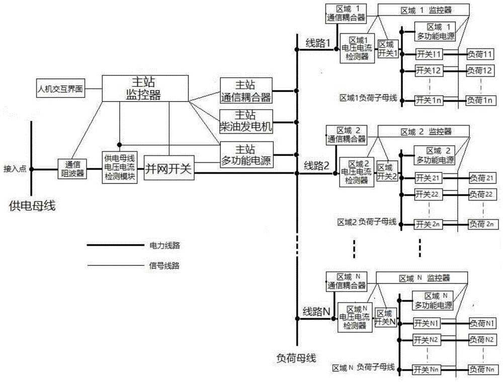
FIG. 1 is a schematic diagram of a system structure of an intelligent high-reliability low-voltage power supply and distribution system based on radial wiring according to the present invention;
FIG. 2 is a schematic block diagram of a master station monitor of the intelligent high-reliability low-voltage power supply and distribution system based on radial wiring according to the present invention;
FIG. 3 is a block diagram of the coordination control unit in the main station monitor of the intelligent high-reliability low-voltage power supply and distribution system based on radial wiring according to the present invention;
FIG. 4 is a functional block diagram of a main station power supply of the intelligent high-reliability low-voltage power supply and distribution system based on radial wiring according to the present invention;
FIG. 5 is a schematic block diagram of a master station diesel generator of the intelligent high-reliability low-voltage power supply and distribution system based on radial wiring according to the present invention;
FIG. 6 is a schematic block diagram of a master station grid-connected switch of the intelligent high-reliability low-voltage power supply and distribution system based on radial wiring according to the present invention;
FIG. 7 is a schematic block diagram of a local monitor of the intelligent high-reliability low-voltage power supply and distribution system based on radial wiring according to the present invention;
FIG. 8 is a block diagram of the coordination control unit in the area monitor of the intelligent high-reliability low-voltage power supply and distribution system based on radial wiring according to the present invention;
FIG. 9 is a schematic block diagram of a regional multifunctional power supply of the intelligent high-reliability low-voltage power supply and distribution system based on radial wiring according to the present invention;
FIG. 10 is a schematic block diagram of the area switch of the intelligent high-reliability low-voltage power supply and distribution system based on radial wiring according to the present invention;
FIG. 11 is a block diagram of the in-zone branch switch of the intelligent high-reliability low-voltage power supply and distribution system based on radial wiring according to the present invention; .
Detailed Description
As shown in fig. 1, the intelligent high-reliability low-voltage power supply and distribution system based on radial wiring comprises a main station device between a power supply bus and a load bus, and N regional station devices between the load bus and a load, wherein N is a natural number greater than or equal to 1;
the master station equipment comprises a master station controller, a master station communication coupler, a master station diesel generator, a master station multifunctional power supply, a communication wave trap, a master station power supply bus voltage and current detection module, a grid-connected switch and a human-computer interaction interface; the current output end of the power supply bus is electrically connected with the communication wave trap, the voltage and current detection module of the main station power supply bus, the grid-connected switch and the current input end of the load bus in sequence; the master station communication coupler, the master station diesel generator and the master station multifunctional power supply are respectively and electrically connected with the load bus; the master station controller is respectively in communication connection with the master station communication coupler, the master station diesel generator, the master station multifunctional power supply, the communication wave trap, the master station power supply bus voltage and current detection module, the grid-connected switch and the human-computer interaction interface; the master station multifunctional power supply is also in communication connection with the master station power supply bus voltage and current detection module, the grid-connected switch and the master station diesel generator respectively;
each regional station device comprises a regional voltage and current detector, a regional switch, a regional communication coupler, a regional multifunctional power supply and a regional controller which are arranged between a load bus and a regional load sub-bus, and n branch switches arranged between the regional load sub-bus and a branch load, wherein n is a natural number which is more than or equal to 1; the current output end of the load bus is electrically connected with the current input end of the regional load son-mother line sequentially through the regional voltage and current detector and the regional switch, and the regional multifunctional power supply is electrically connected with the regional load son-mother line; the zone communication coupler is located between the load bus and the zone voltage current detector; the area coupler needs to be installed on the left side of the area switch, otherwise the area cannot communicate with the outside after the area switch is tripped. The area coupler belongs to area station equipment and is arranged at the tail ends of a line 1 and a line 2 … …, namely a line N; the regional load sub-bus is electrically connected with the n branch switches; the zone controller is in electrical communication with the zone voltage current detector, the zone switch, the zone communication coupler, the zone multifunction power supply, and the n branch switches; the regional multifunctional power supply is in communication connection with the regional switch.
The system is provided with a master station and a plurality of load areas, wherein the master station and each load area are respectively provided with a monitor and a multifunctional power supply; the main station monitor is provided with the highest priority and can enable or close the specific functions of the monitors in each area; the master station multifunctional power supply realizes seamless switching between a power supply bus and a diesel generator by switching between a main power supply mode and an auxiliary power supply mode, and is provided with a function of realizing harmonic wave and reactive dynamic tracking compensation on a system access point; the regional controller is provided with functions of removing faults in the region, trial starting after fault removal and automatic recovery of grid connection, so that self-healing of the faults in the region is realized; the regional multifunctional power supply is provided with a regional trial start function, has a standby power mode and a reactive compensation mode, and realizes a conventional line reactive compensation function and a high-power load auxiliary start compensation function in the reactive compensation mode.
As shown in fig. 2 and 3, the master station controller includes a coordination control unit layer and a functional control unit layer; the coordination control unit layer comprises a master station communication control unit and a master station function coordination control unit; the function control unit layer comprises a power supply bus detection unit, a grid-connected switch control unit, a multifunctional power supply control unit, a diesel generator control unit, a communication wave trap monitoring unit and a communication transceiving control unit; the human-computer interaction interface is in communication connection with the master station communication control unit, and the master station communication control unit is in communication connection with the master station function coordination control unit; the master station function coordination control unit is respectively connected with the diesel generator through the power supply bus detection unit, the grid-connected switch control unit, the multifunctional power supply control unit, the diesel generator control unit, the master station power supply bus voltage and current detection module, the grid-connected switch, the master station multifunctional power supply and the master station diesel generator in a communication mode, and the master station communication control unit is respectively connected with the communication wave trap monitoring unit and the communication transceiving control unit in a communication mode through the communication wave trap and the master station communication coupler.
The main station controller and each zone controller realize the receiving or sending of communication signals inside the system by using the existing power line through the respective main station communication coupler and the zone communication coupler. The master station controller sets the highest priority and may enable or disable the respective zone supervisor functions.
The main station controller sets the power supply priority of each load area and has the function of load shedding and important load protection power supply. When the load bus voltage is detected to be too low, the main station controller sends load cutting instructions to each zone controller step by step according to the preset power supply priority until the load bus voltage recovers to a normal value, and the power supply of the load zone with high priority is ensured.
As shown in fig. 4, the master station multifunctional power supply comprises a master station main control unit, a master station basic control unit and a master station main circuit, wherein the master station basic control unit comprises a master station power supply function realization basic control unit and a master station energy storage element management unit, the main circuit comprises a master station soft start switch group K11, a master station converter circuit unit IGBT11 and a master station energy storage element unit BMS11, the master station power supply bus voltage and current detection module, the grid-connected switch, the master station diesel generator and the master station controller are in communication connection with the master station main control unit, and the master station main control unit is in communication connection with the master station power supply function realization basic control unit and the master station energy storage element management unit; the master station energy storage element BMS11 is in communication connection with the master station energy storage element management unit; the master station soft start switch group K11 and the master station current transformation circuit unit IGBT11 are in communication connection with the master station power supply function realization basic control unit; the main station energy storage element unit BMS11 is electrically connected with the main station current transformation circuit unit IGBT11, the main station current transformation circuit unit IGBT11 is electrically connected with one end of the main station soft start switch group K11, and the other end of the main station soft start switch group K11 is electrically connected with the load bus; a sampling device CPT11 is arranged between the master station soft start switch group K11 and the master station current transformation circuit unit IGBT11, and a signal output end of the sampling device CPT11 is in communication connection with the basic control unit in the master station power supply function; a sampling device CPT12 is arranged between the main station current transformation circuit unit IGBT11 and the main station energy storage element unit BMS11, and the sampling device CPT12 is respectively in communication connection with the main station power supply function realization basic control unit and the main station energy storage element management unit;
the main station multifunctional power supply is provided with a main power supply mode and an auxiliary power supply mode, and is realized by the cooperation of a main station power supply function realization basic control unit and a main station energy storage element management unit; in the main power supply mode, the basic control unit layer controls the main loop, and the energy storage element unit discharges to provide all energy required by the power distribution network. In the auxiliary power supply mode, the energy storage element unit only provides part of energy for compensation or charging required by functions, and main energy required by the power distribution network comes from a power supply bus access point. Different modes and functions are different. The master station controller enables automatic mode switching of the master station multifunctional power supply, and the master station multifunctional power supply realizes seamless switching between the power supply bus and the master station diesel generator. The main power supply mode and the auxiliary power supply mode adopt a set of hardware circuits, and only software control algorithms are different. The software control algorithm relates to four conditions, namely a main power supply control mode and an auxiliary power supply control mode, wherein the main power supply mode is switched to the auxiliary power supply mode, and the auxiliary power supply mode is switched to the main power supply mode, which are all realized by the software control algorithm in a basic control unit layer. Under all working conditions, the energy storage element unit is in a working state. For example, during a main power mode or mode switch, the energy storage element is largely discharged. In the auxiliary mode, the energy storage element is charged or discharged to compensate the energy, or is in a floating state or a trickle-standby state.
Under the condition that the power supply bus normally supplies power, the main station multifunctional power supply is in an auxiliary power supply mode, and dynamic tracking compensation is realized on harmonic waves with variable sizes and frequencies and reactive dynamic loss with variable values.
When the power supply bus normally supplies power and is abnormal, the system trips to a grid-connected switch, and meanwhile, the main station multifunctional power supply is switched from an auxiliary power supply mode to a main power supply mode; the main station multifunctional power supply is used as a main power supply of the system to maintain the voltage and the frequency in the system; and simultaneously starting the diesel generator of the main station, when the diesel generator of the main station is started and enters a normal working state, the multifunctional power supply of the main station is switched from a main power supply mode to an auxiliary power supply mode, and the diesel generator is used as a main power supply of a system to maintain the voltage and the frequency in the system.
When the system detects that the power supply bus is recovered to be normal, the main station multifunctional power supply is switched to a main power supply mode to replace a main station diesel generator to serve as a main power supply of the system, the voltage, the frequency and the phase of the system are adjusted by taking the detected power supply bus as a reference, a grid-connected switch is combined after adjustment is completed, the main station multifunctional power supply is switched to an auxiliary power supply mode from the main power supply mode, and the power supply bus is recovered to supply power to the system.
As shown in fig. 6, the grid-connected switch includes a grid-connected switch controller and a grid-connected switch circuit, the master station controller and the master station multifunctional power supply are in communication connection with the grid-connected switch controller, and the grid-connected switch circuit is a grid-connected switch K601; one end of the grid-connected switch K601 is electrically connected with the power supply bus, and the other end of the grid-connected switch K601 is electrically connected with the load bus; a sampling device CTP601 is arranged between the grid-connected switch K601 and the power supply bus, a sampling device CPT602 is arranged between the grid-connected switch K601 and the load bus, and the signal output ends of the sampling device CTP601 and the sampling device CPT602 are in communication connection with the grid-connected switch controller; the grid-connected switch K601 is in communication connection with the grid-connected switch controller;
as shown in fig. 5, the master station diesel generator includes a master station diesel generator controller and a diesel generator control circuit, and the master station controller and the master station multifunctional power supply are in communication connection with the master station diesel generator controller; the diesel generator control circuit comprises a diesel generator and a diesel generator switch K701, the diesel generator is electrically connected with the load bus through the diesel generator switch K701, a sampling device CPT702 is arranged between the diesel generator and the diesel generator switch K701, and the sampling device CPT701 is arranged between the diesel generator switch K701 and the load bus; the diesel generator, the sampling device CPT702, the sampling device CPT701 and the generator switch K701 are respectively in communication connection with the master station diesel generator controller.
As shown in fig. 7 and 8, the zone controller includes a zone coordination control unit layer and a zone function control unit layer; the regional coordination control unit layer comprises a regional communication control unit and a regional function coordination control unit; the regional function control unit layer comprises a regional detection unit, a regional switch control unit, a regional multifunctional power supply control unit, a branch switch state collection control unit and a communication transceiving control unit; the area communication control unit is in communication connection with the area function coordination control unit; the regional function coordination control unit is in communication connection with the regional voltage and current detector, the regional switch, the regional multifunctional power supply and the n branch switches through the regional detection unit, the regional switch control unit, the regional multifunctional power supply control unit and the branch switch state collection control unit respectively, and the regional communication control unit is in communication connection with the regional communication coupler through the regional communication transceiving control unit.
The regional controller sets the functions of fault removal in the region, trial start after fault removal and automatic recovery of grid connection, and achieves fault self-healing in the region.
And a switch is arranged between each load branch and the regional load sub-bus in the region. When the branch load has a fault, the switch of the branch where the load is located is disconnected, the fault is removed, the area switch is kept closed, the area controller feeds back the disconnection signal of the branch switch which has received the specific fault, and the signal is uploaded to the main station controller to be displayed on the main station human-computer interface.
When a branch load fails and a branch switch where the load is located refuses to operate or a fault point is located on a regional load master-slave line, a regional switch is disconnected, a regional controller uploads a fault message to a main station controller, and the regional multifunctional power supply is authorized to start in a test mode; after the trial starting fails and the fault is still confirmed, the regional controller submits a message to the main controller to require manual troubleshooting; after the trial starting is successful and the fault is confirmed to be eliminated, the regional multifunctional power supply adjusts the voltage, the frequency and the phase in the region by taking the line as a reference, closes a regional switch after the adjustment is finished, and restores the power supply of the line to the region.
As shown in fig. 9, the area multifunctional power supply includes an area main control unit, an area basic control unit and an area main circuit, the area basic control unit includes an area power supply function implementing basic control unit and an area energy storage element management unit, the area main circuit includes an area soft start switch group K21, an area current transformation circuit unit IGBT21 and an area energy storage element unit BMS21, the area controller is communicatively connected to the area main control unit, and the area main control unit is communicatively connected to the area power supply function implementing basic control unit and the area energy storage element management unit; the regional energy storage element unit BMS21 is in communication connection with the regional energy storage element management unit; the region soft start switch group K21 and the region current transformation circuit unit IGBT21 are in communication connection with the region power supply function realization basic control unit; the regional energy storage element unit BMS21 is electrically connected with the regional converter circuit unit IGBT21, the regional converter circuit unit IGBT21 is electrically connected with one end of the regional soft start switch group K21, and the other end of the regional soft start switch group K21 is electrically connected with the regional load son-son wire; a sampling device CPT21 is arranged between the region soft start switch group K21 and the region current transformation circuit unit IGBT21, and the signal output end of the sampling device CPT21 is in communication connection with the region power supply function realization basic control unit; a sampling device CPT22 is arranged between the area current transformation circuit unit IGBT21 and the area energy storage element unit BMS21, and the sampling device CPT22 is respectively in communication connection with the area power supply function realization basic control unit and the area energy storage element management unit;
the regional multifunctional power supply is provided with a regional trial start function. After receiving the authorization of the zone controller, the zone multifunctional power supply tries to establish voltage and frequency as a main power supply in the zone, gradually recovers the power supply of each load branch in the zone, and reports a trial starting result to the zone controller.
As shown in fig. 9, the regional multifunctional power supply is configured with a standby power mode and a reactive power compensation mode, and is implemented by matching a regional power supply function implementation basic control unit and a regional energy storage element management unit; the standby power mode and the reactive compensation mode are jointly realized by a 'power supply function realization basic control unit' and an 'energy storage element management unit' of a basic control unit layer. A set of hardware circuit is adopted, and only the software control algorithm is different. In the standby power mode, the basic control unit layer controls the main loop, and the energy storage element unit discharges to provide all energy. In the reactive compensation mode, the energy storage element unit only provides part of energy or charges the energy for compensation required by the function, and the energy mainly comes from the load bus. The circuit is the same, and the software is different, and different mode, function are different.
The regional multifunctional power supply sets a standby power mode. When the power supply of the line connected with the load bus is abnormal, the regional controller controls to disconnect the regional switch connected with the load bus, and the regional multifunctional power supply is converted into a standby power supply in the region to supply power to the load in the region.
When the power supply of a line connected with the load bus is recovered to be normal, the regional multifunctional power supply adjusts the voltage, the frequency and the phase position in the region by taking the line as a reference, the regional switch is closed after the adjustment is completed, the regional multifunctional power supply is switched from the standby power mode to the reactive power compensation mode, and the line is recovered to supply power to the region.
The regional multifunctional power supply has a reactive compensation mode. Under the reactive mode, the regional multifunctional power supply realizes the reactive compensation function of a conventional line and the auxiliary starting compensation function of a high-power load.
Under normal working conditions, the line reactive loss between the connection load bus and the regional load sub-bus and the regional load reactive loss are relatively stable and cannot change suddenly greatly, and the regional multifunctional power supply only performs stable conventional reactive compensation on the region. When a high-power motor load starts in an area, reactive loss is greatly changed suddenly, so that the voltage of a load sub-bus in the area and even the voltage of a load bus are greatly dropped, the reactive compensation amount of a multifunctional power supply in the area is increased instantly, and the voltage dropping amplitude of the bus is reduced; when the starting is finished, the regional multifunctional power supply is recovered to be only used for stable conventional reactive compensation.
As shown in fig. 10, the area switch includes an area switch controller and an area switch circuit, the area controller and the area multifunctional power supply are in communication connection with the area switch controller, and the area switch circuit is an area switch K501; one end of the area switch K501 is electrically connected with the load bus, and the other end of the area switch K501 is electrically connected with the area load primary-secondary wire; a sampling device CTP501 is arranged between the area switch K501 and the load bus bar, a sampling device CPT502 is arranged between the area switch K501 and the area load sub bus bar, and the signal output ends of the sampling device CTP501 and the sampling device CPT502 are in communication connection with the area switch controller; the area switch K501 is in communication connection with the area switch controller;
as shown in fig. 11, the branch switch includes a branch switch controller and a branch switch circuit, the area controller is in communication connection with the branch switch controller, the branch switch circuit is a branch switch K401, one end of the branch switch K401 is electrically connected to the area load primary and secondary wires, the other end of the branch switch K401 is electrically connected to the branch load, and the branch switch K401 is in communication connection with the branch switch controller.
Embodiment 2, intelligent high-reliability low-voltage power supply and distribution method based on radial wiring, including the following steps:
(1) the method of the installation embodiment 1 is used for building an intelligent high-reliability low-voltage supply and distribution system based on radial wiring to build main station equipment and regional station equipment, and connecting a circuit line and a communication line of the main station equipment and the regional station equipment;
(1-1) selecting a grid-connected switch, a main station diesel generator and a main station multifunctional power supply according to the actual power supply and distribution capacity and voltage grade requirements;
(1-2) selecting a regional switch and a regional multifunctional power supply according to the power consumption capacity and voltage of each load region;
(1-3) selecting a branch switch of a specific load branch according to the specific load size and voltage of a load area;
(1-4) the system sets a master station device: sequentially accessing a communication wave trap, a master station power supply bus voltage and current detection module and a grid-connected switch after a power supply bus access point to reach a load bus; the load bus is electrically connected with the master station communication coupler, the master station diesel generator and the master station multifunctional power supply; setting a main station controller and a human-computer interaction interface; the master station controller is respectively in communication connection with the master station communication coupler, the master station diesel generator, the master station multifunctional power supply, the communication wave trap, the master station power supply bus voltage and current detection module, the grid-connected switch and the human-computer interaction interface; the master station multifunctional power supply is also in communication connection with the master station power supply bus voltage and current detection module, the grid-connected switch and the master station diesel generator respectively;
the system sets regional station equipment of the load region according to the distribution situation of the load region: connecting a power supply line to the load busbar, and connecting a regional voltage and current detection module and a regional switch in sequence after the other end of the line reaches a load region to reach a regional load sub-busbar; the regional load master-slave line is connected with the regional communication coupler and the regional multifunctional power supply; n branch switches between the regional load sub-bus and the branch loads; setting a region controller; the zone controller is in electrical communication with the zone voltage current detector, the zone switch, the zone communication coupler, the zone multifunction power supply, and the n branch switches; the regional multifunctional power supply is in communication connection with the regional switch.
The system is divided into a plurality of load areas according to the positions of loads, and each load area is connected with a load bus of the system main station through respective lines to form radiation type wiring.
(2) The method comprises the steps that the types, characteristics and parameters of equipment in main station equipment and regional station equipment are recorded in a main station human-computer interface, and the load grade and power supply requirement of each load region are set;
(3) inputting a corresponding control strategy on a human-computer interface, controlling the functions of master station equipment and controlling the functions of each regional station equipment;
(4) and starting operation, and then realizing a self-checking state, a static operation state, a dynamic coordination state, a master station equipment fault state and a system shutdown state according to the regional load.
The self-checking state is as follows: the method comprises the following steps of completing system construction, completing strategy presetting of a master station controller and a zone controller, and starting the system, wherein the master station controller carries out self-checking on master station equipment and zone controller equipment to which the zone controller belongs; if the system state is normal, displaying whether to start on a human-computer interaction interface, and waiting for the next operation; if the system has a fault, displaying fault information on a human-computer interaction interface, forbidding starting, and waiting for manual fault removal; if a specific equipment fault is found, shielding the fault equipment on a human-computer interaction interface, or starting self-checking again after manually removing the equipment fault;
the static operating state is as follows: the master station equipment normally runs, and the load in the area is directly started without a high-power motor; the master station diesel generator is in a cold backup non-starting state, and the master station multifunctional power supply is in an auxiliary power supply state; the N regional multifunctional power supplies are in a reactive compensation mode, and only stable conventional reactive compensation is carried out on the regions where the multifunctional power supplies are located.
The dynamic coordination states include 7 dynamic coordination states, which are specifically as follows:
dynamic coordination state 1: the main station equipment normally runs, when a high-power motor is loaded in an area and is directly started, the diesel generator of the main station is in a cold backup non-starting state, and the multifunctional power supply of the main station is in an auxiliary power supply state; the N regional multifunctional power supplies are in a reactive compensation mode, the regional multifunctional power supplies in the regions where the high-power motors are located in the starting process have the function of high-power load auxiliary starting compensation, reactive loss with large mutation is compensated, and voltage fluctuation of regional load sub-buses and load buses is restrained;
dynamic coordination state 2: the main station equipment normally operates, when faults occur in one or more load areas, the branch switch of the branch where the faults are located is tripped, the faults are successfully cut off, the area switch where the faults are located keeps a closed state, and after receiving a branch switch feedback signal, the area controller of the area where the faults are located uploads the branch switch feedback signal to the main station controller, displays the branch switch feedback signal on a human-computer interface and notifies a human to maintain the fault branch;
in the dynamic coordination state 3, the master station equipment normally operates, and after a fault occurs in one or more load areas, the branch switch of the branch where the fault exists refuses to operate, or when the fault point is located on the load master-slave line of the area, the area switch where the fault exists is disconnected; the method comprises the following steps that a region controller where a fault is located and a region multifunctional power supply where the fault is located are matched with each other to achieve the purpose of trying to start, sending a message for applying for re-grid connection to a main station controller, and trying to self-heal the fault in the region in the circulating process of automatically recovering the grid connection function; if the fault self-healing can not be realized, uploading the fault self-healing to a main station controller, displaying the fault self-healing to a human-computer interface, and informing a worker to maintain the fault branch circuit;
state coordination state 4: the main station equipment normally operates, and after a fault occurs in one or more load areas, the branch switch of the branch where the fault exists refuses to operate, or when the fault point is positioned on the load master-slave line of the area, the area switch where the fault exists is disconnected; the fault self-healing in the area dominated by the fault area controller fails, the area switch keeps a disconnected state, and the area controller submits a message to the master station controller and displays the message on a master station human-computer interface to require manual fault removal;
dynamic coordination state 5: the master station equipment normally operates, the voltage of a load bus is low due to low voltage of the power supply bus or overlarge total load of N areas, and the master station controller sends area load cutting instructions to each area controller step by step according to preset power supply priority until the voltage of the load bus returns to a normal value, so that power supply of the load area with high priority is ensured;
dynamic coordination state 6: when the power supply bus is abnormal, the multifunctional power supply of the master station adopts a main power supply mode to seamlessly switch the power supply in the system to the diesel generator of the master station; when the power supply bus is detected to be recovered to normal, the diesel generator is turned off, the main station multifunctional power supply adopts a main power supply mode, and power supply in the system is seamlessly switched back to the power supply bus; the load of each area is in a normal working state;
dynamic coordination state 7: when the power supply bus is abnormal, the main power mode of the main station multifunctional power supply is not enabled, the regional multifunctional power supply is enabled in the standby power mode, each regional controller disconnects the regional switch, and the regional multifunctional power supply enters the standby power mode to supply power to the load in the region; when the condition that the power supply bus is recovered to be normal is detected, the regional multifunctional power supply seamlessly switches the power supply inside the region back to the power supply line bus; the standby power mode of the regional multifunctional power supply is not enabled, and the regional multifunctional power supply interrupts the power supply of the load in the region.
Master station device fault status: the master station equipment breaks down, the standby power mode of the regional multifunctional power supply is enabled, each regional controller disconnects a regional switch, and the regional multifunctional power supply enters the standby power mode to supply power to loads in the region until the energy stored by the regional multifunctional power supply is exhausted; the standby power mode of the regional multifunctional power supply is not enabled, and the load power supply in the region is interrupted;
a system shutdown state: the main station controller is manually shut down on a man-machine interface, the main station controller sends a shut-down instruction to each zone controller, and the system enters a shut-down state.
It should be understood that the above examples are only for clarity of illustration and are not intended to limit the embodiments. Other variations and modifications will be apparent to persons skilled in the art in light of the above description. And are neither required nor exhaustive of all embodiments. And obvious variations or modifications are possible which remain within the scope of the appended claims.