Mounting structure of car engine suspension mounting bracket
Technical Field
The invention relates to the technical field of engine supports, in particular to a mounting structure of a car engine suspension mounting support.
Background
An Engine (Engine) is a machine capable of converting other forms of energy into mechanical energy, and comprises an internal combustion Engine (reciprocating piston Engine), an external combustion Engine (stirling Engine, steam Engine and the like), a jet Engine, an electric motor and the like, and a mounting structure of a suspension mounting bracket of a car Engine is needed when the Engine is mounted.
But current device is fixed firm inadequately when carrying out the during operation, has reduced the practicality to current device can not cushion the vibrations of engine when carrying out the during operation, uses for a long time and can shorten the life of engine.
Disclosure of Invention
The invention aims to provide a mounting structure of a car engine suspension mounting bracket, which aims to solve the problems that the existing device provided in the background technology is not stable enough in fixation during working and the practicability is reduced.
In order to achieve the purpose, the invention provides the following technical scheme: the mounting structure of the suspension mounting bracket of the car engine comprises a bracket, wherein a propping device is arranged above the bracket;
the abutting device comprises a vertical rod, a first gear, a second gear, a double-end stud, a sleeve, a bent rod, a square block, a square shell and a vertical plate;
the lower part of the outer wall of the vertical rod is rotatably connected with the middle part of the support through a bearing, a first gear is arranged above the vertical rod, the left side of the first gear is meshed with a second gear, the inner wall of the second gear is provided with a stud, the middle part of the outer wall of the stud is fixedly connected with the inner wall of the second gear, the left side of the outer wall of the stud is in threaded connection with a sleeve, a bent rod is arranged below the sleeve, the top of the bent rod is fixedly connected with the bottom of the sleeve, a block is arranged below the bent rod, the top of the block is fixedly connected with the bottom of the bent rod, the upper part of the outer wall of the block is in clearance fit with the upper through hole of the square shell, the outer wall of the block is in sliding clamping connection with the inner wall of the square shell, the bottom of the square shell is fixedly connected with the top of the support, a vertical plate is arranged on the left side of the bent rod, and the left side of the outer wall of the bent rod is in clearance fit with the through hole of the vertical plate, the outer wall top of riser rotates with stud's outer wall left side through the bearing and links to each other, the bottom of riser and the top fixed connection of support.
Preferably, the bottom of the vertical rod is provided with a handle.
Preferably, a rubber pad is arranged at the left side of the bent rod.
Preferably, two positioning blocks are arranged above the support, the bottoms of the two positioning blocks are fixedly connected with the left side and the right side of the top of the support respectively, baffle plates are fixedly connected with the left side and the right side of the bottom of the support, two support columns are arranged above the support, the bottoms of the two support columns are attached to the left side and the right side of the top of the support respectively, the outer walls of the two positioning blocks are in clearance fit with through holes of the two support columns respectively, the right side of the support column on the left side is attached to the left side of the bent rod, and a damping device is arranged above the support;
the damping device comprises a shell, a straight plate, a first spring, a transverse plate, a curved plate, a round rod and a second spring;
the bottom left side of the shell is fixedly connected with the top of the left supporting column, a straight plate is arranged in the middle of the shell, the upper portion of the outer wall of the straight plate is in clearance fit with a through hole in the upper portion of the shell, a first spring is arranged below the straight plate, the top of the first spring is fixedly connected with the bottom of the straight plate, a transverse plate is arranged below the first spring, the top of the transverse plate is fixedly connected with the bottom of the first spring, a curved plate is arranged on the left side of the top of the transverse plate, the back of the curved plate is rotatably connected with the top of the transverse plate through a pin shaft, the right side of the outer wall of the curved plate is movably connected with a left groove of the straight plate, the left side of the outer wall of the curved plate is movably connected with a left groove of the transverse plate, the left side of the bottom of the transverse plate is attached to the left side of the shell, a round rod is arranged above the transverse plate, the bottom of the round rod is fixedly connected with the left side of the top of the transverse plate, the upper portion of the outer wall of the round rod is in clearance fit with the through hole in the left side of the top of the shell, the top rigid coupling of diaphragm has the round bar, the outer wall top clearance fit of round bar has the casing, the outer wall clearance fit of round bar has the second spring, the both ends of second spring respectively with the top left side of diaphragm and the inner wall top left side fixed connection of casing.
Preferably, an auxiliary device is arranged above the bracket;
the auxiliary device comprises an engine body, a square rod and a vertical cylinder;
the engine comprises an engine body and is characterized in that the bottom of the engine body is fixedly connected with the top of a straight plate, a square rod is fixedly connected to the left side of the bottom of the engine body, a vertical cylinder is arranged on the outer wall of the square rod in a clearance fit mode, and the right side of the vertical cylinder is fixedly connected with the left side of a shell.
Preferably, the outer wall of the square rod is provided with a rubber sleeve.
Compared with the prior art, the invention has the beneficial effects that: compared with the prior art, the mounting structure of the car engine suspension mounting bracket has the following advantages:
through the cooperation between montant, sleeve and the knee, the handle of the rotatable montant of user, the montant drives first gear revolve, and first gear drives second gear revolve through the meshing, and the stud is driven to rotate by the second gear, because the screw thread of stud both sides is opposite, connects to drive two knee at the live time and supports the pillar tightly, has solved current device and has fixed firm problem inadequately when carrying out the during operation, has improved the practicality.
Through the cooperation between curved bar, second gear and the first gear, the user only need rotate the handle of montant and can accomplish fixedly when fixing the engine body, and whole process is simple swift, has solved the trouble problem of current device fixing process, satisfies modern people's work demand.
Through the cooperation between bent plate, locating piece and the diaphragm, all install the locating piece in the top left and right sides of support, the locating piece can the person of facilitating the use find fixed position for fixed process has improved work efficiency.
Through the straight board, cooperation between bent plate and the diaphragm, vibrations that produce at engine body during operation can drive straight board up-and-down motion, later can first spring take place elastic deformation, straight board drives the bent plate motion simultaneously, the bent plate drives the diaphragm upward movement when the motion, elastic deformation takes place for the second spring this moment, elastic deformation through first spring and second spring buffers vibrations, it can not cushion the vibrations of engine to have solved current device when carrying out the during operation, long-time use can shorten the life's of engine problem.
Drawings
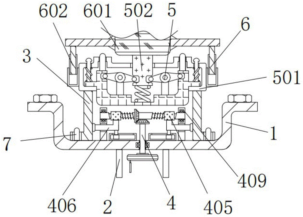
FIG. 1 is a schematic structural view of the present invention;
FIG. 2 is a schematic view of the connection structure of the vertical rod, the sleeve and the curved rod in FIG. 1;
FIG. 3 is a schematic view of the connection structure of the curved bar, the block and the square shell in FIG. 1;
FIG. 4 is a schematic view of the connection structure of the curved plate, the housing and the transverse plate in FIG. 1;
FIG. 5 is a schematic view of the connection structure of the straight plate, the curved plate and the transverse plate in FIG. 1;
FIG. 6 is a schematic view showing a connection structure of the vertical tube, the engine body and the square rod in FIG. 1.
In the figure: 1. the support, 2, baffle, 3, pillar, 4, support tight device, 401, montant, 402, first gear, 403, second gear, 404, stud, 405, the sleeve, 406, the curved bar, 407, the square, 408, the square shell, 409, the riser, 5, damping device, 501, the casing, 502, straight board, 503, first spring, 504, the diaphragm, 505, the bent plate, 506, the round bar, 507, the round bar, 508, the second spring, 6, auxiliary device, 601, engine body, 602, the square bar, 603, the vertical cylinder, 7, the locating piece.
Detailed Description
The technical solutions in the embodiments of the present invention will be clearly and completely described below with reference to the drawings in the embodiments of the present invention, and it is obvious that the described embodiments are only a part of the embodiments of the present invention, and not all of the embodiments. All other embodiments, which can be derived by a person skilled in the art from the embodiments given herein without making any creative effort, shall fall within the protection scope of the present invention.
Referring to fig. 1-6, the present invention provides a technical solution: the mounting structure of the suspension mounting bracket of the car engine comprises a bracket 1, a tightening device 4 is arranged above the bracket 1, the tightening device 4 comprises a vertical rod 401, a first gear 402, a second gear 403, a double-headed stud 404, a sleeve 405, a bent rod 406, a square block 407, a square shell 408 and a vertical plate 409, the lower part of the outer wall of the vertical rod 401 is rotatably connected with the middle part of the bracket 1 through a bearing, the first gear 402 is arranged above the vertical rod 401, the left side of the first gear 402 is meshed and connected with the second gear 403, the inner wall of the second gear 403 is provided with the double-headed stud 404, the threads on two sides of the double-headed stud 404 are opposite, the middle part of the outer wall of the double-headed stud 404 is fixedly connected with the inner wall of the second gear 403, the left side thread of the outer wall of the double-headed stud 404 is connected with the sleeve 405, the bent rod 406 is arranged below the sleeve 405, the top of the bent rod 406 is fixedly connected with the bottom of the sleeve 405, the square block 407 is arranged below the bent rod 406, the top of the square 407 is fixedly connected with the bottom of the bent rod 406, the upper part of the outer wall of the square 407 is in clearance fit with the upper through hole of the square shell 408, the outer wall of the square 407 is in sliding clamping connection with the inner wall of the square shell 408, the square 407 can move inside the square shell 408, the bottom of the square shell 408 is fixedly connected with the top of the support 1, the left side of the bent rod 406 is provided with a vertical plate 409, the left side of the outer wall of the bent rod 406 is in clearance fit with the through hole of the vertical plate 409, the upper part of the outer wall of the vertical plate 409 is rotatably connected with the left side of the outer wall of the stud 404 through a bearing, the bottom of the vertical plate 409 is fixedly connected with the top of the support 1, the bottom of the vertical rod 401 is provided with a handle, a user can conveniently rotate the vertical rod 401, the left side of the bent rod 406 is provided with a rubber pad to increase friction force to tightly abut against the support 1, the two positioning blocks 7 are arranged above the support 1, and the bottoms of the two positioning blocks 7 are respectively fixedly connected with the left side and the left side of the top of the support 1, the left side and the right side of the bottom of the support 1 are fixedly connected with baffle plates 2, two support columns 3 are arranged above the support 1, the bottoms of the two support columns 3 are respectively attached to the left side and the right side of the top of the support 1, the outer walls of the two positioning blocks 7 are respectively in clearance fit with through holes of the two support columns 3, the support columns 3 can move on the outer walls of the positioning blocks 7, and the right side of the left support column 3 is attached to the left side of the bent rod 406;
through the matching among the vertical rod, the sleeve and the bent rod, a user can rotate a handle of the vertical rod, the vertical rod drives the first gear to rotate, the first gear drives the second gear to rotate through meshing, the second gear drives the stud to rotate, and due to the fact that threads on two sides of the stud are opposite, the two bent rods are driven to abut against the support column in the rotating time, the problem that the existing device is not stable enough when in work is solved, and the practicability is improved;
through the cooperation between curved bar, second gear and the first gear, the user only need rotate the handle of montant and can accomplish fixedly when fixing the engine body, and whole process is simple swift, has solved the trouble problem of current device fixing process, satisfies modern people's work demand.
The damping device 5 is arranged above the bracket 1, the damping device 5 comprises a shell 501, a straight plate 502, a first spring 503, a transverse plate 504, a curved plate 505, a round rod 506, a round rod 507 and a second spring 508, the left side of the bottom of the shell 501 is fixedly connected with the top of the left pillar 3, the middle part of the shell 501 is provided with the straight plate 502, the upper part of the outer wall of the straight plate 502 is in clearance fit with a through hole above the shell 501, the first spring 503 is arranged below the straight plate 502, the top of the first spring 503 is fixedly connected with the bottom of the straight plate 502, the transverse plate 504 is arranged below the first spring 503, the top of the transverse plate 504 is fixedly connected with the bottom of the first spring 503, the left side of the top of the transverse plate 504 is provided with the curved plate 505, the back of the curved plate 505 is rotatably connected with the top of the transverse plate 504 through a pin shaft, the curved plate 505 can rotate through the pin shaft, the right side of the outer wall of the curved plate 505 is movably connected with a left groove of the straight plate 502, the left side of the outer wall of the curved plate 505 is movably connected with a left groove of the transverse plate 504, the left side of the bottom of the transverse plate 504 is attached to the left side of the shell 501, a round rod 506 is arranged above the transverse plate 504, the bottom of the round rod 506 is fixedly connected with the left side of the top of the transverse plate 504, the upper side of the outer wall of the round rod 506 is in clearance fit with a through hole in the left side of the top of the shell 501, the round rod 506 can move in the through hole in the left side of the top of the shell 501, a round rod 507 is fixedly connected to the top of the transverse plate 504, the shell 501 is in clearance fit over the outer wall of the round rod 507, a second spring 508 is in clearance fit with the outer wall of the round rod 507, two ends of the second spring 508 are respectively fixedly connected with the left side of the top of the transverse plate 504 and the left side of the top of the inner wall of the shell 501, an auxiliary device 6 is arranged above the support 1, the auxiliary device 6 comprises an engine body 601, a square rod 602 and a vertical cylinder 603, the bottom of the engine body 601 is fixedly connected with the top of the straight plate 502, the left side of the bottom of the engine body 601 is fixedly connected with the square rod 602, the vertical cylinder 603 in clearance fit with the outer wall of the square rod 602, the right side of the vertical cylinder 603 is fixedly connected with the left side of the shell 501, and the outer wall of the square rod 602 is provided with a rubber sleeve to increase friction force and generate damping action;
through the matching among the bent plate, the positioning blocks and the transverse plate, the positioning blocks are arranged on the left side and the right side of the top of the support, and the positioning blocks can facilitate a user to find out a fixed position, so that the fixing process is accelerated, and the working efficiency is improved;
through the straight board, cooperation between bent plate and the diaphragm, vibrations that produce at engine body during operation can drive straight board up-and-down motion, later can first spring take place elastic deformation, straight board drives the bent plate motion simultaneously, the bent plate drives the diaphragm upward movement when the motion, elastic deformation takes place for the second spring this moment, elastic deformation through first spring and second spring buffers vibrations, it can not cushion the vibrations of engine to have solved current device when carrying out the during operation, long-time use can shorten the life's of engine problem.
When the mounting structure of the car engine suspension mounting bracket is used, firstly, the left side and the right side of the top of the bracket 1 are both provided with the positioning blocks 7, the positioning blocks 7 can be convenient for a user to find out a fixed position, the fixing process is accelerated, the working efficiency is improved, then the user can rotate the handle of the vertical rod 401, the vertical rod 401 drives the first gear 402 to rotate, the first gear 402 drives the second gear 403 to rotate through meshing, the second gear 403 drives the stud 404 to rotate, because the threads on the two sides of the stud 404 are opposite, the two bent rods 406 are indirectly driven to support the pillar 3 tightly during rotation, the problem that the existing device is not stable enough during working is solved, the practicability is improved, after the mounting is completed, the vibration generated during the working of the engine body can drive the straight plate 5002 to move up and down, then the first spring 503 can generate elastic deformation, and simultaneously the straight plate 502 can drive the bent plate 505 to move, bent plate 505 drives diaphragm 504 upward movement when the motion, and second spring 508 takes place elastic deformation this moment, cushions vibrations through the elastic deformation of first spring 503 and second spring 508, has solved current device and can not cushion the vibrations of engine when carrying out the during operation, uses the problem that can shorten the life of engine for a long time.
In the description of the present invention, it is to be understood that the terms "coaxial", "bottom", "one end", "top", "middle", "other end", "upper", "one side", "top", "inner", "front", "center", "both ends", and the like, indicate orientations or positional relationships based on those shown in the drawings, and are only for convenience of description and simplicity of description, and do not indicate or imply that the referenced device or element must have a particular orientation, be constructed and operated in a particular orientation, and thus, are not to be construed as limiting the present invention.
In the present invention, unless otherwise expressly specified or limited, the terms "mounted," "disposed," "connected," "secured," "screwed" and the like are to be construed broadly, e.g., as meaning fixedly connected, detachably connected, or integrally formed; can be mechanically or electrically connected; the terms may be directly connected or indirectly connected through an intermediate, and may be communication between two elements or interaction relationship between two elements, unless otherwise specifically limited, and the specific meaning of the terms in the present invention will be understood by those skilled in the art according to specific situations.
Although embodiments of the present invention have been shown and described, it will be appreciated by those skilled in the art that changes, modifications, substitutions and alterations can be made in these embodiments without departing from the principles and spirit of the invention, the scope of which is defined in the appended claims and their equivalents.