CN112429112B - Wheel-foot power switching device based on wheel-walking robot - Google Patents
Wheel-foot power switching device based on wheel-walking robot Download PDFInfo
- Publication number
- CN112429112B CN112429112B CN202011380102.2A CN202011380102A CN112429112B CN 112429112 B CN112429112 B CN 112429112B CN 202011380102 A CN202011380102 A CN 202011380102A CN 112429112 B CN112429112 B CN 112429112B
- Authority
- CN
- China
- Prior art keywords
- wheel
- transmission shaft
- power transmission
- device based
- arm
- Prior art date
- Legal status (The legal status is an assumption and is not a legal conclusion. Google has not performed a legal analysis and makes no representation as to the accuracy of the status listed.)
- Active
Links
Images


Classifications
-
- B—PERFORMING OPERATIONS; TRANSPORTING
- B62—LAND VEHICLES FOR TRAVELLING OTHERWISE THAN ON RAILS
- B62D—MOTOR VEHICLES; TRAILERS
- B62D57/00—Vehicles characterised by having other propulsion or other ground- engaging means than wheels or endless track, alone or in addition to wheels or endless track
- B62D57/02—Vehicles characterised by having other propulsion or other ground- engaging means than wheels or endless track, alone or in addition to wheels or endless track with ground-engaging propulsion means, e.g. walking members
- B62D57/028—Vehicles characterised by having other propulsion or other ground- engaging means than wheels or endless track, alone or in addition to wheels or endless track with ground-engaging propulsion means, e.g. walking members having wheels and mechanical legs
Landscapes
- Engineering & Computer Science (AREA)
- Chemical & Material Sciences (AREA)
- Combustion & Propulsion (AREA)
- Transportation (AREA)
- Mechanical Engineering (AREA)
- Braking Arrangements (AREA)
- Manipulator (AREA)
Abstract
本发明公开了一种基于轮步式机器人的轮足动力切换装置,包括伸缩缸、动力传输轴摇臂、动力传输轴、横向切换机构、纵臂和小腿,纵臂、横向切换机构和小腿依次套设于动力传输轴,伸缩缸的一端铰链固定于底盘上,伸缩缸的另一端与动力传输轴摇臂的一端铰接,动力传输轴摇臂的另一端与动力传输轴的一端连接;伸缩缸伸缩通过动力传输轴摇臂带动动力传输轴转动,横向切换机构切换至不同状态分别与纵臂或小腿连接,动力传输轴通过横向切换机构带动纵臂或小腿动作。本发明使机器人拥有腿式机器人的高越障能力和对复杂环境的高适应能力,同时兼备轮式机器人的高速灵活性能,保证在轮足切换状态下机身的稳定性,结构简单,布置紧凑,提高了空间利用率。
The invention discloses a wheel foot power switching device based on a wheeled robot, which comprises a telescopic cylinder, a power transmission shaft rocker arm, a power transmission shaft, a lateral switching mechanism, a longitudinal arm and a lower leg, and the longitudinal arm, the lateral switching mechanism and the lower leg in sequence Set on the power transmission shaft, one end of the telescopic cylinder is hinged on the chassis, the other end of the telescopic cylinder is hinged to one end of the rocker arm of the power transmission shaft, and the other end of the rocker arm of the power transmission shaft is connected to one end of the power transmission shaft; telescopic cylinder The telescoping drives the power transmission shaft to rotate through the rocker arm of the power transmission shaft, and the horizontal switching mechanism switches to different states to connect with the longitudinal arm or the lower leg respectively, and the power transmission shaft drives the longitudinal arm or the lower leg to move through the horizontal switching mechanism. The invention enables the robot to have the high obstacle-surmounting ability of the legged robot and the high adaptability to complex environments, and simultaneously has the high-speed and flexible performance of the wheeled robot, ensures the stability of the fuselage under the switching state of the wheels and feet, and has a simple structure and compact layout. , improving space utilization.
Description
技术领域technical field
本发明涉及机器人技术领域,具体涉及一种基于轮步式机器人的轮足动力切换装置。The invention relates to the technical field of robots, in particular to a wheel-foot power switching device based on a wheel-step robot.
背景技术Background technique
当今无人地面车辆主要是指轮式和履带式车辆,目前传统单一运动模式的无人车辆在某一领域的应用具备优势,但因自身结构的限制,综合性能提升难度较大,环境适应能力有限。为更好的提升环境适应能力需要在运动模式上进行变化。而轮足式机器人是较为典型的混合式移动机器人,此类型拥有着腿式机器人的高越障能力和对复杂环境的高适应能力,同时兼备轮式机器人的高速灵活性能,被国内外研究人士所青睐,但在轮足动力切换问题上具有较大困难和挑战性。所以本专利提出一种通过控制啮合齿套在传输轴上运动的方式将动力单独驱动纵臂或小腿转动,实现轮足的动力切换。Today's unmanned ground vehicles mainly refer to wheeled and tracked vehicles. At present, unmanned vehicles with a traditional single-motion mode have advantages in the application of certain fields, but due to their own structural limitations, it is difficult to improve their overall performance and environmental adaptability. limited. In order to better improve the ability to adapt to the environment, it is necessary to change the sports mode. The wheel-footed robot is a typical hybrid mobile robot. This type has the high obstacle-surmounting ability of the legged robot and the high adaptability to complex environments, and at the same time has the high-speed and flexible performance of the wheeled robot. However, it is more difficult and challenging to switch between wheel and foot power. Therefore, this patent proposes a way of controlling the movement of the meshing gear sleeve on the transmission shaft to drive the power alone to rotate the trailing arm or the lower leg, so as to realize the power switching of the wheel foot.
发明内容Contents of the invention
本发明要解决的技术问题是,针对现有技术存在的上述缺陷,提供了一种基于轮步式机器人的轮足动力切换装置,实现轮足之间动力切换,使机器人拥有腿式机器人的高越障能力和对复杂环境的高适应能力,同时兼备轮式机器人的高速灵活性能,保证在轮足切换状态下机身的稳定性,结构简单,布置紧凑,提高了空间利用率,集成度高、效率高、操作简单。The technical problem to be solved by the present invention is to provide a wheel-foot power switching device based on a wheeled robot for the above-mentioned defects in the prior art, so as to realize power switching between the wheels and feet, so that the robot has the high Obstacle surmounting ability and high adaptability to complex environments, combined with the high-speed flexibility of wheeled robots, ensures the stability of the fuselage in the state of wheel-foot switching, simple structure, compact layout, improved space utilization, and high integration , high efficiency and simple operation.
本发明为解决上述技术问题所采用的技术方案是:The technical scheme that the present invention adopts for solving the problems of the technologies described above is:
一种基于轮步式机器人的轮足动力切换装置,包括伸缩缸、动力传输轴摇臂、动力传输轴、横向切换机构、纵臂和小腿,纵臂、横向切换机构和小腿依次套设于动力传输轴,伸缩缸的一端铰链固定于底盘上,伸缩缸的另一端与动力传输轴摇臂的一端铰接,动力传输轴摇臂的另一端与动力传输轴的一端连接;伸缩缸伸缩通过动力传输轴摇臂带动动力传输轴转动,横向切换机构切换至不同状态与纵臂或小腿连接,动力传输轴通过横向切换机构带动纵臂或小腿动作。A wheel-foot power switching device based on a wheeled robot, including a telescopic cylinder, a power transmission shaft rocker arm, a power transmission shaft, a lateral switching mechanism, a longitudinal arm and a lower leg, and the longitudinal arm, the lateral switching mechanism and the lower leg are sequentially sleeved on the power The transmission shaft, one end of the telescopic cylinder is hinged on the chassis, the other end of the telescopic cylinder is hinged to one end of the rocker arm of the power transmission shaft, and the other end of the rocker arm of the power transmission shaft is connected to one end of the power transmission shaft; the telescopic cylinder expands and contracts through power transmission The rocker arm drives the power transmission shaft to rotate, the horizontal switching mechanism switches to different states and connects with the longitudinal arm or the lower leg, and the power transmission shaft drives the longitudinal arm or the lower leg to move through the horizontal switching mechanism.
按照上述技术方案,横向切换机构包括套设于动力传输轴上的两个制动盘和接合齿套,两个制动盘分别与纵臂和小腿连接,并分别布置于接合齿套的两侧,接合齿套连接有拨片,接合齿套内圈通过花键与动力传输轴连接,制动盘的内圈布置有内齿花键,接合齿套的外圈布置有外齿花键,接合齿套沿轴向来回移动通过花键与两个制动盘中的一个啮合;动力传输轴通过接合齿套对制动盘进行传动,进而驱动制动盘对纵臂或小腿进行动力传动,达到一个动力源分别驱动纵臂和小腿以及轮足切换的目的。According to the above technical solution, the lateral switching mechanism includes two brake discs and the engaging gear sleeves sleeved on the power transmission shaft, the two brake discs are respectively connected with the trailing arm and the lower leg, and are respectively arranged on both sides of the engaging gear sleeves , the engaging gear sleeve is connected with a paddle, the inner ring of the engaging gear sleeve is connected with the power transmission shaft through splines, the inner ring of the brake disc is arranged with internal tooth splines, the outer ring of the engaging gear sleeve is arranged with external tooth splines, and the joint The gear sleeve moves back and forth along the axial direction and meshes with one of the two brake discs through the spline; the power transmission shaft transmits the brake disc through the engaging gear sleeve, and then drives the brake disc to transmit power to the trailing arm or lower leg, achieving One power source drives the trailing arm and lower leg respectively and the purpose of wheel foot switching.
按照上述技术方案,制动盘上有制动钳,制动钳通过制动钳支架固设于底盘上。According to the above technical solution, the brake disc is provided with a brake caliper, and the brake caliper is fixed on the chassis through the brake caliper bracket.
按照上述技术方案,制动盘的外侧布置有深沟球轴承,制动盘与深沟球轴承之间设有止推轴承;所述的制动盘的内侧是指接合齿套一侧,其反向侧即为外侧。According to the above technical solution, a deep groove ball bearing is arranged on the outer side of the brake disc, and a thrust bearing is arranged between the brake disc and the deep groove ball bearing; The opposite side is the outer side.
按照上述技术方案,制动盘支架固定于底盘上,制动盘与制动盘支架连接。According to the above technical solution, the brake disc support is fixed on the chassis, and the brake disc is connected with the brake disc support.
按照上述技术方案,纵臂和小腿均通过角接触球轴承与动力传输轴套接。According to the above technical solution, both the trailing arm and the lower leg are socketed with the power transmission shaft through angular contact ball bearings.
按照上述技术方案,法兰支座固定于底盘上,动力传输轴通过深沟球轴承与法兰支座连接。According to the above technical proposal, the flange support is fixed on the chassis, and the power transmission shaft is connected to the flange support through deep groove ball bearings.
按照上述技术方案,纵臂的下端设有车轮,车轮连接有轮毂电机。According to the above technical solution, wheels are arranged at the lower end of the trailing arm, and the wheels are connected with hub motors.
按照上述技术方案,底盘上布置有高度传感器,高度传感器安装在纵臂和小腿固定端一侧平齐位置。According to the above technical solution, a height sensor is arranged on the chassis, and the height sensor is installed at a level position on one side of the fixed end of the trailing arm and the lower leg.
按照上述技术方案,伸缩缸为油气簧。According to the technical scheme, the telescopic cylinder is an oil-gas spring.
本发明具有以下有益效果:The present invention has the following beneficial effects:
1、本发明通过横向切换机构实现轮足之间动力切换,使机器人拥有腿式机器人的高越障能力和对复杂环境的高适应能力,同时兼备轮式机器人的高速灵活性能,保证在轮足切换状态下机身的稳定性,结构简单,布置紧凑,提高了空间利用率,集成度高、效率高、操作简单。1. The present invention realizes the power switching between the wheel feet through the horizontal switching mechanism, so that the robot has the high obstacle-surmounting ability of the legged robot and the high adaptability to complex environments, and at the same time has the high-speed flexibility of the wheeled robot, ensuring that the wheel feet The stability of the fuselage in the switching state, the structure is simple, the layout is compact, the space utilization rate is improved, the integration is high, the efficiency is high, and the operation is simple.
2、在传输轴与制动盘有一对角接触球轴承固定,也可承载一定的侧倾力,并根据制动盘上法兰支座和制动钳支架在底盘上的固定,实现系统结构的稳定性;法兰支座配合的深沟球轴承与制动盘之间安装止推轴承,大大降低接触是转动摩擦力;以及通过嵌套在纵臂及小腿上的角接触轴承与传输轴实现固定但不直接由传输轴驱动纵臂和小腿转动;制动钳可以锁止制动盘,实现车身切换时的稳定性。整个轮足传动机构以传输轴和制动盘为核心,将油气簧、支架、轴承等主要结构进行一体化布置。大大节约了结构空间,空间利用率较高。2. There is a pair of angular contact ball bearings fixed between the transmission shaft and the brake disc, which can also carry a certain amount of rolling force, and the system structure is realized according to the flange support on the brake disc and the brake caliper bracket on the chassis. Stability; the thrust bearing is installed between the deep groove ball bearing matched with the flange support and the brake disc, which greatly reduces the contact and rotational friction; and the angular contact bearing and the transmission shaft nested on the trailing arm and lower leg It is fixed but not directly driven by the transmission shaft to rotate the trailing arm and lower leg; the brake caliper can lock the brake disc to achieve stability when the body is switched. The entire wheel foot transmission mechanism takes the transmission shaft and the brake disc as the core, and integrates the main structures such as oil and gas springs, brackets, and bearings. The structural space is greatly saved, and the space utilization rate is high.
附图说明Description of drawings
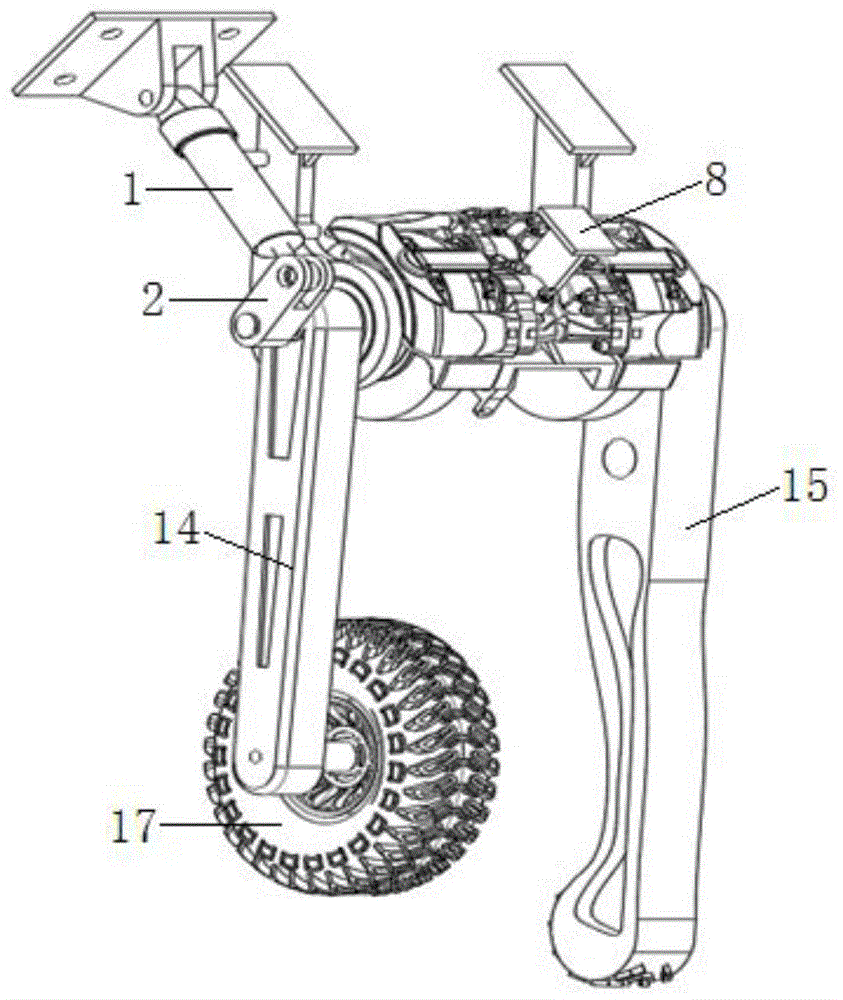
图1是本发明实施例中基于轮步式机器人的轮足动力切换装置的立面图;Fig. 1 is the elevation view of the wheel-foot power switching device based on wheel-walking robot in the embodiment of the present invention;
图2是本发明实施例中基于轮步式机器人的轮足动力切换装置的主视图;Fig. 2 is the front view of the wheel-foot power switching device based on the wheel-walking robot in the embodiment of the present invention;
图3是本发明实施例中横向切换机构的结构示意图;Fig. 3 is a schematic structural diagram of a lateral switching mechanism in an embodiment of the present invention;
图4是图2的后视图;Fig. 4 is the back view of Fig. 2;
图中,1-油气簧,2-动力传输轴摇臂,3-动力传输轴,4-拨片,5-接合齿套,6-制动盘,7-制动钳,8-制动钳支架,9-第一角接触球轴承,10-止推轴承,11-深沟球轴承,12-法兰支座,13-第二角接触球轴承,14-纵臂,15-小腿,16-轮毂电机,17-车轮。In the figure, 1-Oil and gas spring, 2-Power transmission shaft rocker arm, 3-Power transmission shaft, 4-Paddle, 5-Engaging gear sleeve, 6-Brake disc, 7-Brake caliper, 8-Brake caliper Bracket, 9-first angular contact ball bearing, 10-thrust bearing, 11-deep groove ball bearing, 12-flange support, 13-second angular contact ball bearing, 14-trailing arm, 15-shank, 16 -hub motors, 17-wheels.
具体实施方式Detailed ways
下面结合附图和实施例对本发明进行详细说明。The present invention will be described in detail below in conjunction with the accompanying drawings and embodiments.
参照图1~图4所示,本发明提供的一个实施例中的基于轮步式机器人的轮足动力切换装置,包括油气簧1、动力传输轴摇臂2、动力传输轴3、横向切换机构、纵臂14和小腿15,纵臂14、横向切换机构和小腿15依次套设于动力传输轴3,油气簧1的一端铰链固定于机器人底盘上,油气簧的另一端与动力传输轴摇臂2的一端铰接,动力传输轴摇臂2的另一端与动力传输轴3的一端连接;油气簧伸缩通过动力传输轴摇臂2带动动力传输轴3转动,横向切换机构切换至不同状态与纵臂14或小腿15连接,动力传输轴3通过横向切换机构带动纵臂14或小腿15动作。Referring to Figures 1 to 4, the wheel-foot power switching device based on a wheeled robot in an embodiment of the present invention includes an oil-
进一步地,横向切换机构包括套设于动力传输轴3上的两个制动盘6和接合齿套5,两个制动盘6分别与纵臂14和小腿15连接,并分别布置于接合齿套5的两侧,接合齿套5连接有拨片4,接合齿套5内圈通过花键与动力传输轴3连接,制动盘6的内圈布置有内齿花键,接合齿套5的外圈布置有外齿花键,接合齿套5沿轴向来回移动通过花键与两个制动盘6中的一个啮合;动力传输轴3通过接合齿套5对制动盘6进行传动,进而驱动制动盘6对纵臂14或小腿15进行动力传动,达到一个动力源分别驱动纵臂14和小腿15以及轮足切换的目的。Further, the transverse switching mechanism includes two
进一步地,制动盘6上有制动钳7,制动钳7通过制动钳支架8固设于机器人底盘上。Further, there is a brake caliper 7 on the
进一步地,制动盘6的外侧布置有深沟球轴承11,制动盘6与深沟球轴承之间设有止推轴承;所述的制动盘6的内侧是指接合齿套5一侧,其反向侧即为外侧。Further, a deep groove ball bearing 11 is arranged on the outer side of the
进一步地,制动盘支架8固定于机器人底盘上,制动盘6与制动盘支架连接。Further, the
进一步地,纵臂14和小腿15均通过角接触球轴承与动力传输轴3套接。Further, both the
进一步地,法兰支座12固定于机器人底盘上,动力传输轴3通过深沟球轴承与法兰支座12连接。Further, the
进一步地,纵臂14的下端设有车轮17,车轮17连接有轮毂电机16。Further, the lower end of the
进一步地,底盘上布置有高度传感器,高度传感器安装在纵臂14和小腿15固定端一侧平齐位置。Further, a height sensor is arranged on the chassis, and the height sensor is installed at a level position on one side of the fixed end of the
本发明的工作原理:一种基于轮步式机器人的轮足动力切换装置,该机构主要由油气簧1、动力传输轴摇臂2、动力传输轴3、拨片4、接合齿套5、制动盘6、制动钳7、制动钳支架8、第一角接触球轴承9和第二角接触球轴承13、止推轴承10、深沟球轴承11、法兰支座12、纵臂14、小腿15、轮毂电机16、车轮17、高度传感器组成。油气簧1末端铰链固定在底盘上,油气簧连接动力传输轴摇臂2,动力传输轴摇臂2另一端与动力传输轴3连接使其轴转。拨片4固定在接合齿套5上,接合齿套与动力传输轴花键连接。制动盘6分别布置在传输轴两侧,制动钳7固定在制动盘上。制动盘支架8与法兰支座12固定在底盘上,止推轴承10固定在深沟球轴承11与制动盘之间,法兰支座与深沟球轴承配合。第二角接触球轴承13嵌套在纵臂14和小腿15固定端内,高度传感器安装在纵臂和小腿固定端一侧平齐位置。制动盘与纵臂或小腿连接,动力传输轴3通过接合齿套对制动盘进行传动,进而驱动制动盘对纵臂或小腿进行动力传动,达到一个动力源分别驱动纵臂和小腿以及轮足切换的目的。Working principle of the present invention: a wheel-foot power switching device based on a wheel-step robot. Moving
所述油气簧1为推拉杆式,油气簧缸体末端铰链固定在底盘上,油气簧推杆在缸体内腔的往复运动,作为轮足运动的主要动力源。The oil-
所述动力传输轴摇臂2铰链一端与油气簧推杆铰链连接,另一端固定连接在动力传输轴3上,通过油气簧的往复运动驱动传输轴转动。实现将滑动动力源转化为转动动力源。One end of the hinge of the
所述接合齿套5内外侧均布置花键。通过内侧花键固定在动力传输轴中间位置附近,外侧花键可以实现与左右制动盘分别配合,接合齿套中间处设置通孔连接拨片4,拨片4驱动接合齿套在传输轴的花键处左右滑动。以此实现分别对两个制动盘切换式动力传输。Splines are arranged on the inner and outer sides of the engaging tooth sleeve 5 . The inner spline is fixed near the middle of the power transmission shaft, and the outer spline can cooperate with the left and right brake discs respectively. A through hole is set in the middle of the engaging gear sleeve to connect the paddle 4, and the paddle 4 drives the engaging gear sleeve on the transmission shaft. Slide left and right at the spline. In this way, the switchable power transmission to the two brake discs is respectively realized.
所述主要传动制动盘6分别置于传输轴两侧,并通过角接触球轴承与传输轴实现同心配合,利用第一角接触球轴承9降低径向力影响。制动盘靠近接合齿套的一侧布置花键,通过拨片4实现接合齿套与左右制动盘啮合。制动盘外侧与纵臂或小腿固定连接,通过传输轴-接合齿套-制动盘花键配合实现将动力传动到纵臂或小腿。The main
所述制动钳7通过通孔与制动钳支架8固定,并与制动盘同心配合并紧密连接,保证通过制动钳控制动盘的转动。The brake caliper 7 is fixed to the
所述止推轴承10安装在深沟球轴承11与制动盘之间。保证在制动盘转动时不会引起深沟球轴承转动,大幅度减小转向摩擦力。The
所述法兰支座12安装固定在底盘上,并同轴装配在深沟球轴承另一侧。保证在制动盘转动时法兰支座可以固定整个轮足切换装置,保持系统稳定性。The
所述角接触轴承13与传输轴同轴心配合,嵌套在纵臂14和小腿15固定端处,保证传输轴转动时角接触轴承转动但不带动纵臂和小腿转动,实现纵臂和小腿与传输轴同轴心配合时但不直接由传输轴传输动力。The angular contact bearing 13 cooperates with the transmission shaft coaxially, and is nested at the fixed end of the
所述轮毂电机16和车轮17安装在纵臂末端,通过控制轮毂电机16,实现轮式不同时速的运动。The in-wheel motor 16 and the
所述高度传感器18安装在纵臂和小腿固定端一侧平齐位置。实现底盘对地面高度的实时监测。保证在遇到较高路面时通过控制纵臂转动实现车身高度调节以及遇到障碍时切换足式运动越障功能。The
所述在实现轮足切换的同时,制动钳需锁止切换前运动的制动盘,保证切换前的运动状态可以支撑车身高度直至轮足动力切换状态完成。While realizing the switch of wheel and foot, the brake caliper needs to lock the brake disc moving before the switch, so as to ensure that the motion state before the switch can support the height of the vehicle body until the power switch state of the wheel and foot is completed.
以上的仅为本发明的较佳实施例而已,当然不能以此来限定本发明之权利范围,因此依本发明申请专利范围所作的等效变化,仍属本发明的保护范围。The above are only preferred embodiments of the present invention, which certainly cannot limit the scope of rights of the present invention. Therefore, equivalent changes made according to the patent scope of the present invention still belong to the protection scope of the present invention.
Claims (8)
Priority Applications (1)
| Application Number | Priority Date | Filing Date | Title |
|---|---|---|---|
| CN202011380102.2A CN112429112B (en) | 2020-11-30 | 2020-11-30 | Wheel-foot power switching device based on wheel-walking robot |
Applications Claiming Priority (1)
| Application Number | Priority Date | Filing Date | Title |
|---|---|---|---|
| CN202011380102.2A CN112429112B (en) | 2020-11-30 | 2020-11-30 | Wheel-foot power switching device based on wheel-walking robot |
Publications (2)
| Publication Number | Publication Date |
|---|---|
| CN112429112A CN112429112A (en) | 2021-03-02 |
| CN112429112B true CN112429112B (en) | 2023-03-24 |
Family
ID=74698795
Family Applications (1)
| Application Number | Title | Priority Date | Filing Date |
|---|---|---|---|
| CN202011380102.2A Active CN112429112B (en) | 2020-11-30 | 2020-11-30 | Wheel-foot power switching device based on wheel-walking robot |
Country Status (1)
| Country | Link |
|---|---|
| CN (1) | CN112429112B (en) |
Families Citing this family (3)
| Publication number | Priority date | Publication date | Assignee | Title |
|---|---|---|---|---|
| CN113306644B (en) * | 2021-07-01 | 2022-06-07 | 北京理工大学 | Wheel leg mechanism and wheel leg type vehicle using same |
| CN114590337B (en) * | 2022-04-18 | 2023-02-17 | 南京理工大学 | Wheel-foot combined type robot wheel type motion system and robot |
| CN114987642B (en) * | 2022-04-26 | 2023-07-28 | 中国北方车辆研究所 | Driven wheel self-locking anti-skid foot capable of being actively switched |
Family Cites Families (7)
| Publication number | Priority date | Publication date | Assignee | Title |
|---|---|---|---|---|
| PT101340B (en) * | 1993-08-19 | 2001-06-29 | Fernando Jose Nery De Oliveira | SYSTEM FOR VEHICLE OF THE EVERY LAND WITH MEANS OF TRACCAO MOUNTED IN ARTICULATED HANDLES ARMORED |
| CN104494818B (en) * | 2014-11-28 | 2016-12-07 | 吉林大学 | Four rotor amphibious robots |
| CN110304168A (en) * | 2019-07-16 | 2019-10-08 | 深圳市爱因派科技有限公司 | Novel wheel leg composite construction and four-leg bionic robot |
| CN110304167A (en) * | 2019-07-16 | 2019-10-08 | 深圳市爱因派科技有限公司 | Wheel leg composite construction and the compound four-leg bionic robot of wheel leg |
| CN110816704A (en) * | 2019-11-14 | 2020-02-21 | 徐州普瑞赛思物联网科技有限公司 | Intelligent robot for mine gas detection |
| CN111591363B (en) * | 2020-05-27 | 2021-04-27 | 中国人民解放军国防科技大学 | A highly integrated wheel-leg composite mechanism and carrying platform |
| CN111824285B (en) * | 2020-08-14 | 2024-07-26 | 河南锐之信电子技术有限公司 | Multi-leg walking load type robot |
-
2020
- 2020-11-30 CN CN202011380102.2A patent/CN112429112B/en active Active
Also Published As
| Publication number | Publication date |
|---|---|
| CN112429112A (en) | 2021-03-02 |
Similar Documents
| Publication | Publication Date | Title |
|---|---|---|
| CN112429112B (en) | Wheel-foot power switching device based on wheel-walking robot | |
| CN112519913B (en) | An all-terrain adaptive wheel-walking robot | |
| CN101638052B (en) | Wheel assembly with integration of independent driving, steering, suspending and braking | |
| CN105752185B (en) | The serial-parallel machining robot of wheel leg gait switching is realized based on train characteristic changing | |
| US7475745B1 (en) | High mobility vehicle | |
| CN104340291A (en) | Wheel leg type dual-purpose robot | |
| CN110182269A (en) | A kind of achievable wheel carries out the Athey wheel running gear of conversion | |
| CN112623059B (en) | Wheel-leg mechanism of motor vehicle, wheel-leg motor vehicle and wheel-leg motor vehicle set | |
| CN110173607B (en) | Multi-joint omnidirectional movement pipeline robot | |
| CN110296194B (en) | Planetary three-gear shifting device | |
| CN104044658A (en) | Novel walking mechanism of novel wheel and leg combined type mobile robot | |
| CN111845197B (en) | Deformable wheel hub and tire based on wheel type traveling mode and crawler type traveling mode | |
| CN101428652B (en) | Movable robot for ice and snow surface | |
| CN104029746A (en) | Planet gear track combined type traveling mechanism design | |
| CN204488926U (en) | Diagonal angle differential steering four-wheeled | |
| CN113844566B (en) | Wheel-foot type robot leg structure capable of automatically switching power and wheel-foot type robot | |
| CN203864836U (en) | Design of walking mechanism with planet gears and crawler belt combined | |
| CN104691611A (en) | Diagonal differential steering four-wheeler and control method | |
| CN116674662A (en) | An all-terrain crawler mobile robot | |
| CN102424071A (en) | Track-wheel combined type mobile robot | |
| CN119136999A (en) | Wheel-leg mechanism capable of being extended and retracted in both directions and vehicle comprising such wheel-leg mechanism | |
| CN112848792B (en) | Wheel-track combined type reconfigurable wheel | |
| CN116001486A (en) | A deformable chassis with deformable wheels and its working method | |
| CN203331766U (en) | Wheel supporting mechanism of wheeled mobile robot | |
| CN210566982U (en) | Multi-joint omnidirectional movement pipeline robot |
Legal Events
| Date | Code | Title | Description |
|---|---|---|---|
| PB01 | Publication | ||
| PB01 | Publication | ||
| SE01 | Entry into force of request for substantive examination | ||
| SE01 | Entry into force of request for substantive examination | ||
| GR01 | Patent grant | ||
| GR01 | Patent grant |