Retractable panel system
The present invention relates to retractable structures and in particular to a retractable screen/wall/divider/partition which can be extended from a rolled-up state to an extended state and retracted again from the extended state to the rolled-up state. The structure may incorporate one or more split-tube (split tube) extendable members (STEM) to keep it in its extended state, while also allowing it to be rolled around itself into a cylindrical shape for storage, for example. The STEM may not only maintain the rigidity of the structure when extended, but may also be attached to a vertical rod in the structure, in such a way as to help close the STEM so that the cylindrical structure maintains its coiled orientation. Such rod attachments may be used to create a self-closing handle for a screen structure that uses the STEM to create a frame for the screen to be inserted.
Currently, Korn Wall Ltd manufactures the Bi-stable reel Composite (BRC) material technology described in WO 97/35706 "extendable members" and WO 88/08620 "elongated hollow elements" for kwickscreen products, as described in accordance with WO 2010/109247 "screens", EP3251562 "retractable screens" and US20170325605a1 "methods for improving the straightness of the vertical plane of a retractable screen partition". BRC technology allows a rigid hollow split-tube extendable member (STEM) to be rolled up on itself to change from a rolled state (1) to an extended state (2). This is shown in fig. 1.
EP3251562 discloses a rollable screen supported on a frame, the top and bottom of which are formed by STEM; one side of the frame is formed by the housing and the other side is formed by the elongated vertical handle. The screen may be retracted by rolling the screen and the STEM in the housing. In one embodiment, to improve the straightness of a screen, which is typically made of a stiff polymer such as polyester, a small number of widely spaced thin rigid rods are attached to the inside of the screen to keep the STEMs parallel. EP3251562 states that these rods should not be attached to the STEM, as they would then interfere with the rolling up of the STEM. EP3251562 also shows the benefit of having the clip attached to the STEMS so that the handle can be integrated into the screen design. These clamps are all shown to fix the orientation of the STEM, whether the STEM is rolled or flat. Historically, fixed clamps have been used that hold the STEM in a "C" shape to prevent the STEM from fully winding, or in a fixed flat-open state, which helps the STEM to forcibly close, but results in a complex shape of the inner screen to be inserted, creating a risk of the inner screen deforming, wrinkling, or creasing. Ideally, the frame of the interior screen would be uniform and rectangular in shape.
Other known arrangements include those described in EP1594384, US2007193705, US5819835, US5875597 and DE 202011109665.
There is an increasing demand for flexibility in open office and learning environments to create space for centralized work or meeting or presentation banners. Many known portable walls, some of which have been described above, are either bulky, thin and fragile, or complex, making them expensive, unattractive, or impractical for quick and/or frequent use and deployment.
The present disclosure seeks to solve or at least ameliorate problems associated with the prior art.
The present disclosure seeks to provide a portable wall, for example with acoustic properties, which is easy to mount and dismount and which is flexible and easy to store. This may be useful in many such environments, particularly if it is to be intuitively and easily used by people in a space, such as students in public restrooms, workers in open office buildings, promoters at exhibitions.
With the rise of social media and the ability of the public to be able to live streaming video that they can record in smartphones, the present disclosure may also seek to provide a portable privacy structure, screen/wall/partition/baffle that can be used outdoors by emergency services to shield patients from public view during an accident, for example, severely injured football players from fans. Deployable walls of this type may also be used in public gatherings, for example to delineate a workspace for medical personnel without being stepped on by a crowd, for example if someone falls down during a busy street festival date or during a marathon race on a busy route. The same or similar arrangement in printing would be beneficial, for example, for use in indoor or outdoor exhibitions.
The present disclosure describes attaching material to the central region of the convex side of the STEM, such as not to inhibit STEM scrolling or spreading and to take advantage of the structural/functional benefits from state transitions.
The present application also describes a new method of attaching a handle to the STEM to adequately hold the two together, and as such to allow the STEM to freely change from a curved state to a flat state, which introduces a positive ('snap') closure feature that is beneficial when the handle is fully retracted toward the structural direction, yet creates a neat rectangular frame for the interior screen to be inserted.
Various new structures are also disclosed, fig. 17 being but one example (reference numerals provided for clarity, but not limiting the disclosure in any way) made of a partially cut solid sheet material 41, such that the front face 48 is cut and the core portion is partially cut, such that the back face 47 is a hinge about which the sheet material may be rolled. Ideally, the structure is supported by the STEM 3 along its central region to provide both rigidity when extended and cylindrical support when retracted.
According to a first aspect of the present disclosure there is provided a system comprising a retractable panel structure, for example a rollable and spreadable screen/wall/partition, wherein the planar structure comprises a back face and a front face spaced from each other, and wherein the front face is at least partially formed from an array of strips which are independent of each other and move apart to cause the panel structure to be rolled up, and wherein the back face forms a hinge which connects the strips together and which is bendable to cause the strips to move apart as the sheet is rolled up.
Optionally, when the sheeting is spread, the strips in each pair of adjacent strips abut one another or are separated by an interval less than or equal to twice the width of the wider strips in the strip.
Optionally, when the sheeting is spread, adjacent strips abut one another or are separated by a spacing less than or equal to the width of the wider strip in the pair of adjacent strips.
Alternatively, the structure is formed of a front sheet and a back sheet and a cell or less dense material separating the front sheet and the back sheet.
Alternatively, the strip is formed by scoring or cutting or routing the front face.
Optionally, the structure has a thickness of 0.1 to 25mm, such as 1 to 15mm, such as 3 to 10 mm.
Optionally, the strips each have a width of 0.5 to 100mm, for example 1 to 50mm, for example 2 to 5mm or 10 to 40 mm.
Alternatively, the spacing between each pair of adjacent strips is typically less than or equal to 100mm, such as less than or equal to 50mm, such as less than or equal to 10 mm.
Optionally, the system comprises a support configured to support the structure in its deployed configuration.
Optionally, the support comprises at least one STEM that is extendable along an axis by unwinding the STEM and retractable along the same axis by winding the STEM, and wherein the structure is supported on the at least one STEM by an attachment that causes the structure to be rolled up and spread when the at least one STEM is wound and unwound.
Optionally, the at least one STEM is positioned adjacent to the back side of the structure, and optionally attached to the back side.
Optionally, the at least one STEM is positioned adjacent a region of the back face of the structure, and wherein the back face comprises a slit in said region, the slit coinciding with a spacing between the strips in the front face, such that when the STEM and structure are rolled together the back face extends in said region, while when the STEM and structure are rolled together at least one other region of the structure forms said hinge, the strips being bendable about said hinge.
Optionally, the at least one STEM has a concave side and a convex side when extended, and wherein the structure is attached to a central area of the convex side of the STEM, e.g., to the central axis of the STEM or an area adjacent to the central axis, e.g., by adhesive, welding, stitching, rivets, eyelets, or by frangible attachments (e.g., hook and loop connections).
Optionally, the support comprises at least two STEMs spaced apart from each other and extendable along parallel axes, and wherein the structure is supported by the at least two STEMs.
Optionally, the STEM is configured to expand horizontally, upwardly or downwardly, including being tilted upwardly or downwardly or curved inwardly or outwardly.
Optionally, the support comprises a housing supporting the at least one STEM, a rotatable reel within the housing, and wherein the structure can be rolled up on the reel.
Optionally, the reel comprises a base plate configured to support the system when wound on the reel.
Optionally, the system includes a spring acting on the spool to assist in rolling up the structure.
Optionally, the support comprises a handle supporting an end of the at least one STEM distal from the housing.
Optionally, the front face includes a notch in the area where the STEM is located, whereby when the STEM is rolled up, the back face is stretched outwardly and the front face is squeezed inwardly.
Optionally, the support comprises at least two posts attached to the structure and extending parallel to the strip, whereby the posts can be rolled up with the structure.
Optionally, the support comprises at least one STEM attached to the post.
Optionally, the system comprises at least one fastener that holds the structure in its rolled state, such fastener may be for example hook and loop (velcro), press studs or magnetic fasteners.
Optionally, the system takes the form of: temporary or permanent indoor or outdoor screens, room dividers, doors (such as sliding doors (e.g., garage doors)), awnings, curtains or blinds, acoustic screens, portable divider screens, screens in MRI scanning rooms where the entire system is non-ferrous, and can optionally be used as a white board, blackboard, projection surface, pin board and/or hook and loop board, poster, mirror, solar array, mirror film surface, satellite dish, decorative panel, photovoltaic solar array, flexible television or monitor (e.g., OLED TV), or LED light, or as a support structure to which other materials can be attached, e.g., to provide the above-described functionality.
According to a second aspect of the present disclosure, there is provided a split-tube extendable member (STEM) system comprising: at least one windable STEM having a central axis and being extendable along the axis by unwinding the STEM and being retractable along the same axis by winding the STEM, wherein the STEM has a tip that forms a leading end of the STEM when unwound, and wherein the STEM has a concave side and a convex side when extended/unwound; and a handle attached to the convex side of the at least one STEM front end by one or more connections, whereby, upon retraction, the winding action of the STEM front end biases the handle toward the remainder of the wound STEM.
Optionally, the handle engages the ground when the at least one windable STEM has been extended and thereby supports the leading end of the STEM.
Optionally, the handle is supported on at least one caster or runner.
Optionally, the connection on the convex side of the handle attached to the front end of the at least one STEM is located on or near the central axis of the STEM.
Optionally, the front end of the at least one windable STEM is clamped flat against the handle.
Optionally, when extended, the STEM has a width of 50mm to 100mm, preferably 65-85mm, more preferably about 75mm, and subtends an arc of 100 degrees to 180 degrees, preferably about 130 degrees.
Optionally, the system includes a housing for holding a coiled portion of the at least one windable STEM.
Optionally, the housing engages the ground and optionally includes at least one caster or runner.
Optionally, the system includes a screen attached to the at least one STEM by an attachment that winds and unwinds the at least one STEM and the screen together.
Optionally, the system includes at least two STEMs spaced apart from each other and extendable along parallel axes, and wherein the screen is supported by the at least two STEMs along opposing edges.
Optionally, the handle, the at least two STEMs, and the housing form a rectangular frame that supports the screen.
Optionally, at least one STEM is mounted on the reel.
Optionally, the roller is biased by a spring configured to assist retraction of the screen.
Optionally, the front end of the at least one STEM is attached directly to the handle at a single point, e.g. by means of an adhesive or mechanical fixation, e.g. by means of stitching, welding, adhesive, rivets or eyelets, optionally in combination with bolts.
Optionally, the front end of the at least one STEM is curved or angled/chamfered in shape (i.e., the end of the STEM is not orthogonal to the central axis of the STEM).
Optionally, the system comprises a clamp that clamps the at least one STEM portion of the path along a length of the at least one STEM portion of the path and prevents the STEM from forming the concave and convex sides in a region of the clamp, resulting in kinking of the STEM in the region of the clamp.
Optionally, the system takes the form of: temporary or permanent indoor or outdoor screens, room dividers, display screens, safety screens for laser or X-ray or welding, doors (such as drop doors (e.g., garage doors)), canopies, curtains or blinds, acoustic screens, portable divider screens, screens in MRI scanning rooms where the entire system is non-ferrous, and can optionally be used as a whiteboard, blackboard, projection surface, patch and/or hook and loop board, poster, mirror, solar array, mirror film surface, satellite dish antenna, decorative panel, photovoltaic solar array, flexible television or monitor (e.g., OLED), or LED light, or as a support structure that can be attached to other materials, for example to provide the above-described functionality.
Optionally, the at least one STEM is configured to expand horizontally, upwardly or downwardly, including being angled upwardly or downwardly or curved inwardly or curved back.
Features from one or more aspects, or any optional feature thereof, may be combined together.
The present disclosure may be carried out in various ways, and embodiments of the disclosure will now be described, by way of example, with reference to the accompanying drawings, in which:
FIG. 1 shows a basic split-tube extendable member.
FIG. 2 shows an isometric view of a split-tube extendable member.
FIG. 3 shows the difference in transitions between split-tubes with greater and less than 180 degrees of arc.
Figure 4 shows the basic frame of two pipes and some rods.
Fig. 5 shows different designs of the lower profile end of the hole with different designs.
Fig. 6 shows the effect of different designs of slats (curved rectangular, rectangular and circular) on the rolled STEM.
Figure 7 illustrates how varying the attachment of the rod to the tube can create an angled profile (two dimensional and axonometric views).
Fig. 8 and 9 illustrate the positioning of the holes in the tube and flat bar.
Fig. 10 shows a button ring on the STEM edge.
Figure 11 illustrates different possible shapes of the rigid backing material.
Fig. 12 shows the relationship between the width, spacing and height of the slats in the front face.
Fig. 13 shows the main body housing of an empty room divider screen, without a screen or handle.
Figure 14 shows a room divider screen with its housing and casters in a closed configuration.
Figure 15 shows a room divider screen with the housing and casters in an open and kinked configuration.
Fig. 16 shows the position of the central region attached to the convex side of the STEM.
Figure 17 shows the structure when made from a rigid plate that is completely cut open.
Fig. 18A, 18B, and 18C illustrate a method of attaching a STEM to a structure.
Fig. 19 shows a structure made from individual slats secured along a centerline.
Fig. 20 shows a frame system where the STEM is attached to the support rather than directly to the slit sheet material.
Fig. 21A and 21B show how rollable slit rigid plates are created and how the STEM forces the slits to expand open when the back side is rolled up on the structure.
Fig. 22 shows the desired orientation of the STEM on the back side.
Figure 23 illustrates a different rigid plate configuration with an outer portion cut away to reveal a flexible inner core that can be hinged.
Fig. 24A, 24B, 24C show how the structure is made more stable by preventing the STEM from straightening and adding support base features.
Fig. 25A and 25B illustrate a handle attached to the convex side of the front end of the STEM along the centerline of the STEM.
Fig. 26 shows different profiles of STEM front end.
Fig. 27 illustrates how fasteners such as shackles can be used to help control the cylindrical structure of the system.
Fig. 28A and 28B show the configuration of the system with the STEM in the router portion that is straight and attached to the front face when rolled.
Fig. 29 shows the handle and handle base of a wall-mounted retractable screen without a housing.
Fig. 30A shows the handle when the handle is open and the STEM is straight.
Fig. 30B shows the handle when the screen is closed and the STEM is bent and the handle is held close to the body.
Fig. 31 illustrates another example system with a handle attached thereto.
Fig. 32A and 32B illustrate an example system with a handle attached in front and back views.
Fig. 33A shows the system with the handle attached when both screens are extended.
Fig. 33B shows a system with two screens extended.
Fig. 34 illustrates the bending of the STEM and how to create a complex spline shape to be cut from the internal screen.
Fig. 35 shows how a clamp holding the STEM flat creates a complex shape to fit the interior screen in.
Figure 36A illustrates various possible fastener locations symmetrically disposed about an axis for STEM attachment to a handle.
Fig. 36B illustrates a handle attached to a STEM having a straight leading edge and a beveled leading edge in an open and closed configuration.
Fig. 37 shows the front and back of the rigid plate partially cut away.
In one example, STEM 3, which extends from the screen, is attached to vertical handle 38. Ideally, this fixation is by means of a single fastener that is dispersed across the centerline 4 or near the centerline 4 on the outer/convex surface of the STEM 3 (fig. 36A) so that it allows the STEM 3 to click open and closed freely (fig. 25A and B, fig. 36B). The handle 38 of the system can then be a simple small aluminum extrusion or rod to which each STEM 3 is fixed on the outer surface using a fixing (fig. 30A and B). Alternatively, handle 38 could be a squeeze housing, but connected to STEM 3 by this simple means to create an arrangement that looks similar to that shown in FIG. 35, but where the edges of STEM 3 are always horizontal, while the portion of interior screen 10 is simply rectangular. A simple handle 38 can be attached to the base plate 5 and will therefore create a very narrow minimal design arrangement (fig. 29). It is integrated with a similarly simple body 8 with minimal metal exposure, as shown in fig. 29. The screen system may include two different systems to create a double screen that may be hinged in the middle, both systems being attached at the front handle 38 (as shown in fig. 32) or at the main body 8 (as shown in fig. 33) of one of the systems. A corner of 3m x 3m can be created where the angle between the two screens can be changed (fig. 33B).
By changing the free end 55 of STEM 3Contour (fig. 26), the force of click-close can be varied. A curved incision may be more desirable to prevent sharp edges and will also reduce the force to close and open the tip of STEM 3. The free end 55 will be exposed and will change the shape of the click as it closes and opens. Therefore, it may be necessary to coat this part of the c-tube 3 with a rubber coating (for example Plastidip)TM) To protect it from wear and to provide aesthetic improvements on the exposed leading edge 55 without affecting its ability to undergo the required complex shape changes.
The new clamping method provides the screen element of this arrangement with a rectangular frame in which the screen element is seated, thereby eliminating the need to cut a complex geometry "spline" 9 as shown in fig. 35 from the non-elastic material used to make the screen 10. This overcomes one of the problems identified in patent EP3251562 "retractable screen". Fig. 34 shows the change in edge shape of STEM 3 and how the splines 9 cut into the screen material 10 are needed to seat the screen material 10 without undesirable forces. These unwanted forces are still typically present as the shape of the splines 9 created under the STEM 3 changes as the STEM 3 retracts. Figure 35 shows the effect of the shape of the splines 9 on the screen 10.
Fig. 21A shows how the rigid plate 41 may be partially cut on its front face 48 to roll up the rigid plate 41. This may be created by partially cutting 42, 43 the full length with a knife or routing grooves 42, 43 that partially penetrate the material along the full length. Various possible shapes of the router profile are discussed in fig. 11 and 12. If the plate 41 is not made of a very rigid material (e.g., felt), the plate 41 may be reinforced by attaching the plate 41 to a lightweight rigid backing structure (e.g., a cellular polypropylene structure). Alternatively, it may be supported by attachment to a more rigid support. These supports may be attached to the STEM 3, and may also be attached to the plate material 41 (fig. 20), so the plate material 41 would not need to be attached to the STEM 3.
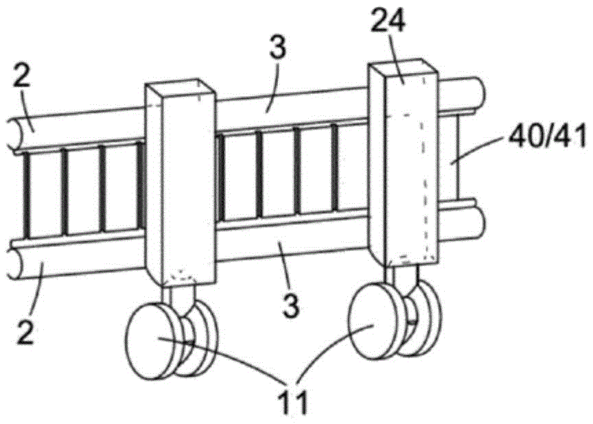
Fig. 20 illustrates how STEM 3 can be attached to a few more robust slats or rods 40 to create a frame in which other less robust slats 40 can fit. This has the advantage that the slats 40 supporting the STEM 3 can be more robust, as they provide a body of structural support and can be attached to the caster 11. The structure inside the frame provides only a visual barrier and may therefore be far less robust. As shown in fig. 17, 43A and 43B, this configuration may be used to accommodate the slit plate configuration 41. The support member 40 may be made of wood (e.g., Venetian blinds), aluminum, or PVC extrusions (e.g., roller blind panels). The method creates a frame in which various rollable inner members can be inserted. This has the advantage for the slit plate design that the plate 41 will not need any full depth cut-outs 43 anymore, since the plate 41 will never stretch out when rolling around the STEM 3, but can roll around the same plane and let the STEM 3 roll up either side of the material.
Fig. 22 shows the desired orientation of STEM 3 on the back face 47, which causes the slits 42, 43 to stretch and expand as they roll up. When STEM 3 is secured to the back 47, the back 47 will still have to stretch slightly to cause it to scroll around STEM 3. If STEM 3 were attached to front face 48, back face 47 would have to stretch more because its radius of curvature would increase due to the thickness of panel 41 and the thickness of STEM 3. Therefore, it is generally desirable to secure the STEM 3 to the back 47 and to have the back 47 stretch by a minimum amount when the back 47 is rolled around the STEM 3. Some or all of the partial slits 42, 43 need to be full cuts 42, 43, which full cuts 42, 43 penetrate the panel 41 to expand the back surface 47 44, similar to how a chinese lantern works when compressed, as shown in fig. 21B. Ideally, the full cuts 42, 43 are at least the width of the flat STEM 3 and may extend up to the full width of the plate 41. The longer and closer these full cuts 43 are, the easier it is to scroll because the less force is exerted on them for expansion. If the full cuts 42, 43 are short or absent, the slit plate 41 will be difficult to roll up and there will be a force in the system to spread out like a spring, becoming flat with chance. This feature is desirable if a quick deployment configuration is desired (e.g., when used as an emergency privacy screen). In such a case, the rolls may be secured together with a fastener such as hook and loop Velcro (Velcro)56, 57 which when removed causes the leading edge of the structure to be manually unwound, thereby initiating automatic further full unwinding (unwinding)/unwinding (deployment) of the structure. It may be desirable to attach STEM 3 to front face 48 because this provides a large, flat and unobstructed back face 47 to which, for example, a whiteboard or printed display may be attached. In such a case, the front face 48 may be routed to create a channel 60, and the STEM 3 may be seated in the channel 60 (fig. 28A), thereby securing itself to the back of the back face 47, thereby reducing the amount of expansion of the back face 47 required to scroll around the STEM 3 (fig. 28B). An additional advantage for the STEM 3 routing channel 60 to be installed in is that the roll diameter of the cylinder 1 will be kept to a minimum (fig. 28B) since the thickness of the STEM 3 is hidden within the channel 60.
The
panel 41 is desirably made of a material that is rigid when thick but flexible when thin. In this way, the living hinge can be made by partially cutting 42, 43. Preferably, the outer faces 47, 48 of the
plate 41 are made of a denser and stronger material than the
inner core 49. This increases the second moment of the structural area, making it stiffer for a given weight, and also helps create a hinge that is less likely to fail. Such as plastic coated foam board, semi-rigid PET felt board with a treated or laminated outer surface, or thin wood sheets that can be rolled up when cut, cardboard with a cellular structure, etc. One desirable material to be used is PET felt, which also has the benefits of sound absorption, aesthetics, printability, ease of lamination, ease of machining and cutting. There are many such materials available, for example Cube from Autex
TM、Symphony
TMAnd Composition
TMOr PolySorber-fire resistant PET printable acoustical panels from Tech Materials. These septum sheets are self supporting plates that can be easily cut 42, 43 and routed 60. These materials may be laminated to create a layer that facilitates rolling, and rigid supports may be added and hidden in the router's grooves to create the desired panel configuration. Another desirable material is PVC rigid or laminated sheets. The
uncut back face 47/skin acts as a hinge when cutting the
front face 48/skin and core of either 42, 43 or
router 60. One material suitable for this is Sealwise
TM。Sealwise is a homogeneous material with a foam core made of closed cell PVCU and a surface of solid PVC material. Sealwise is non-toxic, formaldehyde free and non-porous and can be used and processed using the same methods as the panel product, but provides longer tip life. However, due to similar characteristics, density and weight comparable to MDF, it can be processed using the same techniques. It can be machined, cut, CNC, routed, shaped and trimmed the same as MDF. It is 100% waterproof, making it hygienic and suitable for the harsh environment of the inside and outside. Some materials are inherently "fluted", such as corrugated cardboard, "fluted polypropylene" corex
TMAnd certain wood laminates. These cause them to be partially cut 42, 43 along the grain to pierce the front face 48 (the top layer of the skin) and not the back face 47 (the bottom layer of the skin). The material then hinges easily and naturally around the
back face 47. Other well-working materials are honeycomb core cardboard and polypropylene construction, with the
back surface 47 providing the hinge and the core and
top layers 48 providing the structure. Alternatively, there are materials similar to aluminum facesheets with plastic cores, commonly referred to as
But wherein the Dibond has a rigid core and these materials have a flexible
inner core 49, see fig. 23. By routing aluminum on either side of the
flexible core 49, hinges may be created in other rigid materials. Fig. 23 is a different configuration in which the outer faces 47, 48 are rigid and the
inner face 49 is flexible. The hinged flexible Dibond material can be rolled and expanded around
STEM 3 unimpeded by slitting the flexible
inner core 49 in a manner similar to that described in that patent.
If the cuts 42, 43 and router 60 are made in the manner described above and combined with the support bar 23 and stabilizing base 5 as described in this patent, a variety of interesting and useful roll-up structures can be created without the need for the STEM 3 to support. Instead of the function of STEM 3 in extended state 2, other methods of reinforcing the extension structure may be used, such as a rigid member or a telescopic member fixed along the length. However, it may not be necessary if the structure itself is sufficiently rigid. In addition to cost savings, an advantage of not using STEM 3 is that the extension structure can be bent into an "S" shape, since STEM 3 kinks 14 in only one direction (like an elbow). Instead of the function of STEM 3 in the rolled-up state 1, other methods of keeping the cylinders 8, 38 closed may be used, such as magnets or hook and loop fasteners 56, 57 between the inner and outer faces of the rolling structure. Thus, the structure described in this patent using the same principles but without STEM 3 is possible.
The structure of laths 40 (fig. 19) or slit plate 41 (fig. 17/21) may create a reinforced support frame for attachment of the rollable material 10 to the back side 47. One example is a flexible, erasable writable surface that when adhered to back surface 47 will form a rollable whiteboard. Alternatively, the display may be fixed on the back 47 to create a roll bar display (rolout display) for exhibition or advertising. The front side 48 may be printed directly on or coated in the stretchable fabric and the structure may be used as a flexible room divider. Flexible solar panels can be secured on the back to create an expandable solar cell that can be retracted, for example, in inclement weather. Other technical applications are OLED flexible televisions and deployable antennas. The structure may be used to support Concrete fabrics (e.g. Concrete Canvas)TM) And sprayed with water to create a concrete wall. Multiple structures can be attached together, e.g. using zippers/VelcroTMSnap fasteners, etc. create an expandable structure for use in emergency shelters where large open spaces typically need to be periodically reconfigured to provide privacy to the citizens.
Fig. 24A, B and C show how any STEM structure mentioned in this patent can be made more stable by preventing the STEM 3 from straightening out 51 (fig. 24A) completely along its full length (resulting in the structure lying in one plane that is unstable and prone to toppling). If STEM 3 is fixed 54 on the structure along its centerline 4, it is free to roll up 1 and spread 2. However, if STEM 3 is fixed 46 to the structure off its centerline 4, ideally using two fasteners 46 near the STEM 3 edge, above and below well above or well below centerline 4, it cannot be converted to straight/extended orientation 2, but is forced to remain in coiled orientation 1 (fig. 24). If this is done at both ends, the structure will have a bending characteristic at both ends to provide some additional stability (FIG. 24C). If done in the middle of the structure, it will form a kink 14 (FIG. 24C) at the point where it imparts greater stability (FIG. 24C). By adding casters 11 and/or base 5 to the supports 8, 38, a simple stable structure can be formed (fig. 24B). Another way to help improve the stability of the STEM structure is to make the STEM 3 not straight but arcuate when retracted 2. By modifying the recipe of STEM 3, it can be made to bow back on itself or to bow on itself. Such banana shape with STEM 3 bent inwards or outwards will not only create a more stable structure but will also create a more aesthetic screen, e.g. for exhibition backgrounds/booths where curved walls are often used.
In one embodiment, the sheet of flashing material 41, such as grooved polypropylene CORREX, is partially cut every 1-10cm on the outer surfaceTMOr SealwiseTM. These slits 42, 43 extend all the way to the back only behind the position where the STEM is attached. The minimum width of these full cuts 42, 43 can be the width of the STEM 3 (currently 150mm) and the maximum can be the full length of the groove (e.g. the height of the plate), but at the top and bottom there is left a portion that is not a fully cut area so that the structure does not completely separate into individual slats. Ideal CORREX for this purposeTMThe thickness of the material is about 5mm-10mm, and the ideal SealwiseTMThe thickness of the plate is 3-6 mm. The STEM 3 can be sewn 45 along the centerline 4 or fixed to the structure every 5-50cm by mechanical fasteners or rivets. The height of the structure is 1-3m, and the width is 2-5 m. Two STEM 3 are used, extending in the width direction. 200-500mm from the edge. The final structure is a lightweight, weatherproof, expandable wall that when printed can be used as an advertising banner, for example for outdoor displays, or can be used as an emergency privacy screen, for example for emergency services. STEM 3 is made of polypropylene, so the structure is fully recyclable except for the fixing, which may be plastic. During the course of its manufacture, the material is,a polypropylene felt layer may be applied to corexTMThereby creating a soft processed version of the arrangement in a cost-effective manner. Both sides of the structure can be coated with aesthetic and sound insulating fabric as can STEM 3 to create soft furnishing, sound absorbing room partitions in offices, private work areas, etc. Additional functionality may be added by integrating a magnetic or dry erase surface and/or a projection surface. The structure is lightweight and rigid and can therefore be raised and fitted to the castor wheel 11, making it easier to carry. Several of these systems can be connected to each other by means of magnets, zippers or velcro along the leading edge to create a continuous wall, as shown by elements 56, 57 in fig. 27. The caster wheels 11 can be secured to the structure in a minimum number of positions to maintain stability without the need to support a structural span, as this capability is inherent in the design of a self-supporting structure. Ideally, the castor 11 would be under the extreme ends of the curve at the left and right ends as illustrated in fig. 24C, and the other or both would be off-centre along the body 8 to prevent it from tipping backwards (fig. 24B). Without the caster 11, this structure has the following advantages: it can be used in any way (upside down).
Another embodiment of any of the structures described may be in a vertical/lowered orientation (e.g., garage door), in a pull-up orientation (vertical wall or OLED TV) or in a horizontal pull-out orientation (window awning/expandable acoustic roof). The descending oriented screen can be used to create ultra wide curtains, displays, sound screens mounted on the ceiling or raised from the floor. The canopy structure can create a self-supporting blind that requires less infrastructure and is less likely to degrade for weather reasons, as they will be rigid structures in nature rather than strictly taught fabrics (as is the case with standard ultrawide canopies).
The structure can be further improved by adding a spring core and a swivel base plate 35 (fig. 13), said swivel base plate 35 being configured to support the system when wound onto the reel 35, which will reduce friction and facilitate rolling (fig. 13). This would mean that the user would not have to manually spread and roll the structure, but could pull and push the handle 38, which handle 38 would unroll the structure. The handle 38 may be the portion with the spool 35 therein or may be a loose end. The rotor core 38 may be assisted by a mechanical spring or an electrical spring.
It may be necessary to scroll the structure from both ends, creating two cylindrical rollers that meet in the middle. This may be because the outer diameter of the entire cylinder may be too large for STEM 3, or because it is cumbersome to use. A structure can be created such that the two cylinders meet along the same plane (C-shaped as shown in fig. 24B). However, if STEM 3 is to be cut and rotated around a configuration where the cylinders meet back-to-back, an S-shaped configuration can be provided that is more stable because the ends will bend in the opposite direction. This also means that the structure can kink in two orientations when the top of the S is bent in different directions towards the bottom. In any of the above orientations, the structure may be designed such that the free ends may be attached to each other, thus creating a linked structure that may create a variety of shapes, for example, for reconfiguring a large open space to be an area of a different flexible design partition.
One embodiment is an acoustic felt panel cut to create a rolled room divider with the additional function of a whiteboard, a projector surface, a needle board, and/or a hook and loop board. Or from the same design concept, using a lower cost and weatherproof corexTMGrooved polypropylene or grooved seawingTMPanels, creating outdoor weatherproof partition structures from any other rigid material that is similarly cut.
If the full cuts 43 in the sheet material 41 were to extend the full length of the material, individual battens 40 would be created (FIG. 17). A similar configuration may be one in which the slats 40 are not adjacent to one another but are spaced apart (fig. 19). The slats 40 shown in fig. 19 are desirably lightweight and ridged and thin, such as the wood slats found in venetian blinds. To add structure to the back of the slat 40, the slat 40 may be attached to a film material, such as a polyester film or an adhesive vinyl or felt. This will create a rolled up mat. STEM 3 (or another support material) can be added continuously to the structure, for example by sewing through STEM 3 along the centerline 4 into the slat 40 and/or base film, or STEM 3 can be attached non-continuously to the structure, for example rivets or eyelets spaced along STEM 3 and connected to some or all of the slats 40 (fig. 18). These various attachment methods are also effective for the rigid plate 41 method (fig. 17). Non-continuous methods (e.g., eyelets) may require few fasteners, but ideally at least one fastener per meter. The orientation of the slats 40, film and STEM 3 is important because the structure requires the STEM 3 to be rolled up freely.
Figure 4 shows the basic framework of two tubes 3 and a plurality of rods 22. In this embodiment, two or more tubes 3 may be connected to each other to obtain the advantages described above. The rod 22 comprises a resilient central portion 24 and thinner flatter portions at both ends (rod 23) that interact with the split-tube 3. The rod 23 may extend beyond the open face of the tube 3 or may be positioned against one of the inner surfaces. For example, a ladder structure may be constructed by extending two tubes 3 and then attaching the rigid member 22 perpendicular to the rigid member 22.
Fig. 5 shows different designs of the lower profile end 23 with holes of different designs. A rigid rod 24 may be attached directly to the tube 3 or to help reduce the effect on the OD of the tube 3, a lower profile portion called a flat bar 23 may be connected to the rod 24, the width of the rod 24 being wide enough to allow the tube 3 to flatten out at its surface. The method of connecting the rod 24 and the flat bar 23 is varied-some examples are shown in figure 5. The flat bar 23 may be of any low profile shape, but may be a flat face, generally rectangular in cross-section-preferably a curved rectangular cross-section to match the arc of the rolled tube 2 is the most preferred profile, as the width of the bar 23 affects the OD much less than the thickness. See fig. 6.
The flat bar 23 may be attached to the tube 3 in a variety of ways. The preferred method is by means of a non-elastic string or wire 21 (fig. 7, 8 and 9) with a small diameter (e.g. fishing line). The cord 21 may simply be wrapped around the outside of the rod 23 and tube 3 to secure the two together. However, this simple method of assembly will provide limited support along the line of the rod 24 (i.e. the rod can slide out). There are four holes in each element through which the wire 21 passes for attachment, the presence of which prevents the rod 24 from moving laterally, laterally and rotationally relative to the tube 3, thus providing the most secure fit.
By locating the position of the hole, the tightness of the tube 3 against the rod 23 can be controlled, and this can create a predetermined kinked shape, wherein the wire 21 passes through the tube 3 and the rod 23 via the hole.
Fig. 8 and 9 show the mechanical principle behind the positioning of the holes in the tube 3 and the flat bar (23).
Figure 8 shows how the holes can be positioned to provide a loose fit when the tube is flat (rolled) 1 and a tight fit when the tube is bent (extended) 2.
Figure 9 shows how the holes can be positioned to provide a tight fit when the tube is flat (rolled) 1 and a loose fit when the tube is bent (extended) 2.
Varying the position of the rod 23 and/or the holes in the tube 3 can adjust the effect to produce a mixture of the two to achieve the desired effect for a particular application.
Other forms of attachment include adhering or mechanically securing one edge of the split-tube 3 to the rod 23, wrapping the fabric around the rod 23 and tube 3, attaching a tab with hinged holes 25 to the edge of the tube 3 into which the rod 23 can be inserted, inserting the rod into the 23 hole through the hook-the hinged holes 25 can simply be a loop of wire, similar to a button secured to the back of a garment. See fig. 10, which shows the button ring 25 on the edge of the split-tube 3.
The following is a list of reference numerals shown in the drawings.
1. Rolled tube
2. Extended pipe
3. Split tube STEM
4. Center line of split pipe
5. Substrate
8. Main body
9. Splines cut in inner panels
10. Inner panel
11. Caster wheel
14. Kinking in split-tube
20. Rod
21. Inelastic cords or filaments
22. Rod
23. Stick
24. Elastic central part
25. Button ring
35. Thrust bearing rotating disc
36. Housing for holding main body of rolled material screen
37. Smooth protective surface
38. Front handle of system
40. Rigid panel
41. Solid plate material
42. Partial slit incision
43. Full through slit incision
44. Expansion slit effect
45. Suture along STEM centerline
46. Hole for fixing
47. Back side of the panel
48. Front side
49. Flexible inner core
51. Flat material
52. Rolled material
53. Foot extension
54. Holes for attachment on STEM centerline
STEM front edge
56. Velcro hook
57. Velcro ring
58. Open and flat V-shaped incision
59. Closed and curved V-shaped incision
60. STEM accommodating router feature