CN112476830B - Rubber particle forming process and rubber particles - Google Patents
Rubber particle forming process and rubber particles Download PDFInfo
- Publication number
- CN112476830B CN112476830B CN202011258828.9A CN202011258828A CN112476830B CN 112476830 B CN112476830 B CN 112476830B CN 202011258828 A CN202011258828 A CN 202011258828A CN 112476830 B CN112476830 B CN 112476830B
- Authority
- CN
- China
- Prior art keywords
- plunger
- cutting
- forming
- mixing
- rubber
- Prior art date
- Legal status (The legal status is an assumption and is not a legal conclusion. Google has not performed a legal analysis and makes no representation as to the accuracy of the status listed.)
- Active
Links
Images


Classifications
-
- B—PERFORMING OPERATIONS; TRANSPORTING
- B29—WORKING OF PLASTICS; WORKING OF SUBSTANCES IN A PLASTIC STATE IN GENERAL
- B29B—PREPARATION OR PRETREATMENT OF THE MATERIAL TO BE SHAPED; MAKING GRANULES OR PREFORMS; RECOVERY OF PLASTICS OR OTHER CONSTITUENTS OF WASTE MATERIAL CONTAINING PLASTICS
- B29B9/00—Making granules
- B29B9/02—Making granules by dividing preformed material
- B29B9/06—Making granules by dividing preformed material in the form of filamentary material, e.g. combined with extrusion
-
- B—PERFORMING OPERATIONS; TRANSPORTING
- B29—WORKING OF PLASTICS; WORKING OF SUBSTANCES IN A PLASTIC STATE IN GENERAL
- B29B—PREPARATION OR PRETREATMENT OF THE MATERIAL TO BE SHAPED; MAKING GRANULES OR PREFORMS; RECOVERY OF PLASTICS OR OTHER CONSTITUENTS OF WASTE MATERIAL CONTAINING PLASTICS
- B29B7/00—Mixing; Kneading
- B29B7/02—Mixing; Kneading non-continuous, with mechanical mixing or kneading devices, i.e. batch type
- B29B7/06—Mixing; Kneading non-continuous, with mechanical mixing or kneading devices, i.e. batch type with movable mixing or kneading devices
- B29B7/10—Mixing; Kneading non-continuous, with mechanical mixing or kneading devices, i.e. batch type with movable mixing or kneading devices rotary
- B29B7/12—Mixing; Kneading non-continuous, with mechanical mixing or kneading devices, i.e. batch type with movable mixing or kneading devices rotary with single shaft
- B29B7/14—Mixing; Kneading non-continuous, with mechanical mixing or kneading devices, i.e. batch type with movable mixing or kneading devices rotary with single shaft with screw or helix
-
- B—PERFORMING OPERATIONS; TRANSPORTING
- B29—WORKING OF PLASTICS; WORKING OF SUBSTANCES IN A PLASTIC STATE IN GENERAL
- B29B—PREPARATION OR PRETREATMENT OF THE MATERIAL TO BE SHAPED; MAKING GRANULES OR PREFORMS; RECOVERY OF PLASTICS OR OTHER CONSTITUENTS OF WASTE MATERIAL CONTAINING PLASTICS
- B29B9/00—Making granules
- B29B9/12—Making granules characterised by structure or composition
-
- C—CHEMISTRY; METALLURGY
- C08—ORGANIC MACROMOLECULAR COMPOUNDS; THEIR PREPARATION OR CHEMICAL WORKING-UP; COMPOSITIONS BASED THEREON
- C08L—COMPOSITIONS OF MACROMOLECULAR COMPOUNDS
- C08L23/00—Compositions of homopolymers or copolymers of unsaturated aliphatic hydrocarbons having only one carbon-to-carbon double bond; Compositions of derivatives of such polymers
- C08L23/02—Compositions of homopolymers or copolymers of unsaturated aliphatic hydrocarbons having only one carbon-to-carbon double bond; Compositions of derivatives of such polymers not modified by chemical after-treatment
- C08L23/16—Ethylene-propylene or ethylene-propylene-diene copolymers
-
- C—CHEMISTRY; METALLURGY
- C08—ORGANIC MACROMOLECULAR COMPOUNDS; THEIR PREPARATION OR CHEMICAL WORKING-UP; COMPOSITIONS BASED THEREON
- C08L—COMPOSITIONS OF MACROMOLECULAR COMPOUNDS
- C08L91/00—Compositions of oils, fats or waxes; Compositions of derivatives thereof
- C08L91/06—Waxes
-
- C—CHEMISTRY; METALLURGY
- C08—ORGANIC MACROMOLECULAR COMPOUNDS; THEIR PREPARATION OR CHEMICAL WORKING-UP; COMPOSITIONS BASED THEREON
- C08K—Use of inorganic or non-macromolecular organic substances as compounding ingredients
- C08K3/00—Use of inorganic substances as compounding ingredients
- C08K3/18—Oxygen-containing compounds, e.g. metal carbonyls
- C08K3/24—Acids; Salts thereof
- C08K3/26—Carbonates; Bicarbonates
- C08K2003/265—Calcium, strontium or barium carbonate
-
- Y—GENERAL TAGGING OF NEW TECHNOLOGICAL DEVELOPMENTS; GENERAL TAGGING OF CROSS-SECTIONAL TECHNOLOGIES SPANNING OVER SEVERAL SECTIONS OF THE IPC; TECHNICAL SUBJECTS COVERED BY FORMER USPC CROSS-REFERENCE ART COLLECTIONS [XRACs] AND DIGESTS
- Y02—TECHNOLOGIES OR APPLICATIONS FOR MITIGATION OR ADAPTATION AGAINST CLIMATE CHANGE
- Y02W—CLIMATE CHANGE MITIGATION TECHNOLOGIES RELATED TO WASTEWATER TREATMENT OR WASTE MANAGEMENT
- Y02W30/00—Technologies for solid waste management
- Y02W30/50—Reuse, recycling or recovery technologies
- Y02W30/62—Plastics recycling; Rubber recycling
Landscapes
- Chemical & Material Sciences (AREA)
- Engineering & Computer Science (AREA)
- Mechanical Engineering (AREA)
- Health & Medical Sciences (AREA)
- Chemical Kinetics & Catalysis (AREA)
- Medicinal Chemistry (AREA)
- Polymers & Plastics (AREA)
- Organic Chemistry (AREA)
- Oil, Petroleum & Natural Gas (AREA)
- Processing And Handling Of Plastics And Other Materials For Molding In General (AREA)
Abstract
本发明涉及橡胶加工领域,更具体的说是一种橡胶颗粒成型工艺及橡胶颗粒,具有能快速成型出橡胶颗粒的优点,一种橡胶颗粒成型工艺,包括以下步骤:S1:首先,将橡胶成型原料放置在混合容器中并在混合容器中充分混合;S2:其次,将混合后的原料加压添加到橡胶颗粒成型组件中成型出长条状材料;S3:最后,对长条形材料进行导出、切割和收集,实现橡胶颗粒的成型;该橡胶颗粒由以下重量份数的原料组成:乙丙橡胶15份;碳酸钙40份;交联剂6份;过氧化物硫化剂8份;石蜡油15份;颜料6份;柠檬香精5份。
The present invention relates to the field of rubber processing, and more specifically relates to a rubber particle forming process and rubber particles, which have the advantage of being able to rapidly form rubber particles. A rubber particle forming process includes the following steps: S1: first, forming the rubber The raw materials are placed in the mixing container and fully mixed in the mixing container; S2: secondly, the mixed raw materials are added under pressure into the rubber particle forming assembly to form long strips of material; S3: finally, the long strips of material are exported , cutting and collecting to realize the molding of rubber particles; the rubber particles are composed of the following raw materials by weight: 15 parts of ethylene-propylene rubber; 40 parts of calcium carbonate; 6 parts of cross-linking agent; 8 parts of peroxide curing agent; paraffin oil 15 parts; 6 parts pigment; 5 parts lemon essence.
Description
技术领域technical field
本发明涉及橡胶加工领域,更具体的说是一种橡胶颗粒成型工艺及橡胶颗粒。The invention relates to the field of rubber processing, in particular to a rubber particle forming process and rubber particles.
背景技术Background technique
公开号为CN201710976030.X的发明公开了一种橡胶颗粒及其制备方法,由若干个橡胶颗粒组成,部分橡胶颗粒的部分表面为拉伸断裂的裂面,部分橡胶颗粒具有至少一个结晶区域,结晶区域包含碳化硅;每个橡胶颗粒由橡胶颗粒A和橡胶颗粒B组成,橡胶颗粒A的硬度小于橡胶颗粒B的硬度;橡胶颗粒B的平均粒度比橡胶颗粒A的平均粒度大至少三倍;橡胶颗粒B的平均粒度为300微米,橡胶颗粒A的平均粒度为30微米;橡胶颗粒A和橡胶颗粒B均由以下重量配比的原料制成:乙丙橡胶28;碳酸钙80;交联剂8;过氧化物硫化剂8;石蜡油28;颜料3。该发明制备方法简单,制备出的橡胶颗粒具有高耐天然老化性能,产品无腐蚀性,物理性能好。该发明的缺点是不能快速成型出橡胶颗粒。The invention with the publication number CN201710976030.X discloses a rubber particle and a preparation method thereof, which is composed of several rubber particles. The region contains silicon carbide; each rubber particle consists of a rubber particle A and a rubber particle B, the hardness of the rubber particle A is less than that of the rubber particle B; the average particle size of the rubber particle B is at least three times larger than the average particle size of the rubber particle A; the rubber The average particle size of particles B is 300 microns, and the average particle size of rubber particles A is 30 microns; both rubber particles A and rubber particles B are made of the following raw materials by weight: ethylene propylene rubber 28; calcium carbonate 80;
发明内容SUMMARY OF THE INVENTION
本发明的目的是提供一种橡胶颗粒成型工艺及橡胶颗粒,具有能快速成型出橡胶颗粒的优点。The purpose of the present invention is to provide a rubber particle forming process and rubber particles, which have the advantage of being able to rapidly form rubber particles.
本发明的目的通过以下技术方案来实现:The object of the present invention is achieved through the following technical solutions:
一种橡胶颗粒成型工艺,包括以下步骤:A rubber particle forming process, comprising the following steps:
步骤一:首先,将橡胶成型原料放置在混合容器中并在混合容器中充分混合;Step 1: First, place the rubber molding raw materials in a mixing container and mix them thoroughly in the mixing container;
步骤二:其次,将混合后的原料加压添加到橡胶颗粒成型组件中成型出长条状材料;Step 2: secondly, the mixed raw materials are added under pressure into the rubber particle forming assembly to form long strips of material;
步骤三:最后,对长条形材料进行导出、切割和收集,实现橡胶颗粒的成型;Step 3: Finally, export, cut and collect the long strip material to realize the molding of rubber particles;
上述橡胶颗粒的成型工艺中还涉及一种橡胶颗粒成型装置;The above-mentioned rubber particle forming process also relates to a rubber particle forming device;
所述的橡胶颗粒成型装置,包括定成型组件、导流注入组件、动成型组件、柱塞组件、驱动组件、出料组件、裁切组件和混合组件,其特征在于:所述导流注入组件固定连接在定成型组件上,动成型组件转动连接在定成型组件上,柱塞组件滑动连接在导流注入组件上,驱动组件固定连接在导流注入组件上,驱动组件和柱塞组件啮合传动,驱动组件和动成型组件带传动,出料组件和裁切组件均固定连接在定成型组件上,出料组件和裁切组件啮合传动,驱动组件和出料组件带传动,混合组件通过螺栓可拆卸连接在导流注入组件上。The rubber particle forming device includes a fixed forming component, a diversion injection component, a dynamic forming component, a plunger component, a driving component, a discharging component, a cutting component and a mixing component, and is characterized in that: the diversion injection component It is fixedly connected to the fixed forming component, the dynamic forming component is rotatably connected to the fixed forming component, the plunger component is slidably connected to the diversion injection component, the driving component is fixedly connected to the diversion injection component, and the driving component and the plunger component engage and drive , The driving component and the dynamic forming component are driven by the belt, the discharging component and the cutting component are fixedly connected to the fixed forming component, the discharging component and the cutting component are meshed and driven, the driving component and the discharging component are driven by a belt, and the mixing component is detachably connected by bolts on the diversion injection assembly.
所述定成型组件包括定支架、定成型架、定成型槽、导出架和导出管,定成型架固定连接在定支架上,定成型架上均布有多个定成型槽,导出架固定连接在定成型架的右端,导出架上均布有多个导出管,多个导出管和多个定成型槽一一对应。The shaping component includes a fixed bracket, a shaping frame, a shaping slot, a lead-out frame and a lead-out pipe, the shaping frame is fixedly connected to the fixed bracket, a plurality of shaping slots are evenly distributed on the shaping frame, and the exporting frame is fixedly connected At the right end of the shaping frame, a plurality of outlet pipes are evenly distributed on the outlet frame, and the plurality of outlet tubes are in one-to-one correspondence with the plurality of shaping grooves.
所述导流注入组件包括导流支架、导流框、导向架、柱塞孔、混合桶、输出泵和添加管,导流支架固定连接在定支架上,导流框固定连接在导流支架上,导流框的前后两侧均固定连接有导向架,导流框内均布有多个柱塞孔,混合桶固定连接在导流支架上,混合桶上固定连接有添加管,添加管上设置有输出泵,多个柱塞孔分别和多个定成型槽一一对应。The diversion injection assembly includes a diversion bracket, a diversion frame, a guide frame, a plunger hole, a mixing tank, an output pump and an addition pipe. The diversion bracket is fixedly connected to the fixed bracket, and the diversion frame is fixedly connected to the diversion bracket. On the front and rear sides of the guide frame are fixedly connected with guide frames, a plurality of plunger holes are evenly distributed in the guide frame, the mixing tank is fixedly connected to the guide bracket, and the mixing tank is fixedly connected with an addition pipe, and the addition pipe An output pump is arranged on the upper part, and a plurality of plunger holes correspond to a plurality of shaping grooves one-to-one respectively.
所述动成型组件包括成型转轮、成型输出轮、成型输入轮、输入齿形带和输出齿形带,成型转轮转动连接在定支架上,成型转轮上设置有成型输出轮和成型输入轮,成型转轮上设置有多个转动成型槽,多个转动成型槽分别和多个定成型槽一一对应。The dynamic forming assembly includes a forming runner, a forming output wheel, a forming input wheel, an input toothed belt and an output toothed belt, the forming runner is rotatably connected to the fixed bracket, and the forming runner is provided with a forming output wheel and a forming input The forming runner is provided with a plurality of rotating forming grooves, and the plurality of rotating forming grooves are respectively in one-to-one correspondence with the plurality of fixed forming grooves.
所述柱塞组件包括柱塞连接板、柱塞导向杆、复位弹簧、柱塞杆和柱塞齿条,柱塞连接板上固定连接有两个柱塞导向杆,两个柱塞导向杆分别滑动连接在两个导向架上,两个导向架和柱塞连接板之间均设置有复位弹簧,柱塞连接板上固定连接有多个柱塞杆,柱塞连接板的前端固定连接有柱塞齿条。The plunger assembly includes a plunger connecting plate, a plunger guide rod, a return spring, a plunger rod and a plunger rack, and two plunger guide rods are fixedly connected on the plunger connecting plate, and the two plunger guide rods are respectively The two guide frames are slidably connected, and a return spring is arranged between the two guide frames and the plunger connecting plate. A plurality of plunger rods are fixedly connected to the plunger connecting plate, and a column is fixedly connected to the front end of the plunger connecting plate. Plug the rack.
所述驱动组件包括电机、驱动缺齿齿轮和驱动全齿齿轮,电机固定连接在导流框上,电机的输出轴上固定连接有驱动缺齿齿轮和驱动全齿齿轮,驱动缺齿齿轮和柱塞齿条啮合传动,成型输入轮和驱动全齿齿轮通过输入齿形带传动。The drive assembly includes a motor, a driving gear with missing teeth and a driving full-tooth gear. The motor is fixedly connected to the guide frame, and the output shaft of the motor is fixedly connected with a driving gear with missing teeth and a driving full-tooth gear, and a driving gear with missing teeth and a column. The plug and rack are meshed for transmission, and the forming input wheel and the driving full-tooth gear are driven by the input toothed belt.
所述出料组件包括出料转轮架、出料转轮、出料输入轮和出料输出轮,两个出料转轮架均固定连接在定成型架上,出料转轮转动连接在出料转轮架上,出料输入轮固定连接在出料转轮上,出料输入轮和成型输出轮通过输出齿形带传动。The discharging assembly includes a discharging runner frame, a discharging runner, a discharging input wheel and a discharging output wheel. The two discharging runner frames are fixedly connected to the setting frame, and the discharging runner is rotatably connected to On the discharge runner frame, the discharge input wheel is fixedly connected to the discharge runner, and the discharge input wheel and the forming output wheel are driven by the output toothed belt.
所述裁切组件包括裁切导向架、裁切刀、裁切弹簧和裁切齿条,裁切导向架固定连接在定成型架上,裁切刀滑动连接在裁切导向架上,裁切导向架和裁切刀的上端之间设置有两个裁切弹簧,裁切刀的前后两侧均固定连接有裁切齿条,两个裁切齿条分别和两个出料输出轮啮合传动。The cutting assembly includes a cutting guide frame, a cutting knife, a cutting spring and a cutting rack. The cutting guide frame is fixedly connected to the shaping frame, the cutting knife is slidably connected to the cutting guide frame, and the cutting guide frame is Two cutting springs are arranged between the cutting blade and the upper end of the cutting blade. The front and rear sides of the cutting blade are fixedly connected with cutting racks, and the two cutting racks are respectively engaged with the two discharge output wheels for transmission.
所述混合组件包括盖、加热炉、连通管、混合架、混合电机和混合叶轮,盖通过螺栓可拆卸连接在混合桶上,盖上设置有加热炉,加热炉上设置有连通管,混合架固定连接在盖上,混合电机固定连接在混合架上,混合叶轮固定连接在混合电机的输出轴,混合叶轮转动连接在连通管上。The mixing assembly includes a cover, a heating furnace, a communication pipe, a mixing rack, a mixing motor and a mixing impeller, the cover is detachably connected to the mixing barrel through bolts, a heating furnace is arranged on the cover, a communication pipe is arranged on the heating furnace, and the mixing rack is It is fixedly connected to the cover, the mixing motor is fixedly connected to the mixing frame, the mixing impeller is fixedly connected to the output shaft of the mixing motor, and the mixing impeller is rotatably connected to the communication pipe.
采用上述的一种橡胶颗粒成型工艺制成的橡胶颗粒,该橡胶颗粒由以下重量份数的原料组成:乙丙橡胶15份;碳酸钙40份;交联剂6份;过氧化物硫化剂8份;石蜡油15份;颜料6份;柠檬香精5份。The rubber particles made by adopting the above-mentioned rubber particle molding process, the rubber particles are composed of the following raw materials by weight: 15 parts of ethylene-propylene rubber; 40 parts of calcium carbonate; 6 parts of cross-linking agent; 8 parts of peroxide vulcanizing agent parts; 15 parts of paraffin oil; 6 parts of pigment; 5 parts of lemon essence.
本发明一种橡胶颗粒成型工艺及橡胶颗粒的有益效果为:本发明一种橡胶颗粒成型工艺及橡胶颗粒,通过混合组件对橡胶成型原料进行融化和混合,为橡胶颗粒的成型提供原料,还可以通过驱动组件啮合驱动柱塞组件升降,实现将导流注入组件内的原料加压添加到定成型组件和动成型组件之间进行成型,再通过驱动组件带动动成型组件转动实现成型橡胶的自动出料和为原料的持续成型提供空间,再通过动成型组件带动出料组件转动实现出料组件带动成型的橡胶进行出料,再通过出料组件啮合驱动裁切组件实现裁切组件对成型的橡胶进行切割获得橡胶颗粒,实现橡胶颗粒的快速成型。The rubber particle forming process and the beneficial effects of the rubber particles of the present invention are as follows: the rubber particle forming process and the rubber particles of the present invention melt and mix the rubber forming raw materials through the mixing component to provide the raw materials for the forming of the rubber particles, and can also Through the engagement of the driving component to drive the plunger component to rise and fall, the raw material injected into the component is pressurized and added between the fixed molding component and the dynamic molding component for molding, and then the driving component drives the dynamic molding component to rotate to realize the automatic discharge of the molding rubber. It provides space for the continuous molding of raw materials, and then drives the discharge component to rotate through the dynamic forming component to realize the discharge component drives the formed rubber to discharge, and then drives the cutting component through the meshing of the discharge component to realize the cutting component. The rubber particles are obtained by cutting, and the rapid prototyping of the rubber particles is realized.
附图说明Description of drawings
下面结合附图和具体实施方法对本发明做进一步详细的说明。The present invention will be described in further detail below with reference to the accompanying drawings and specific implementation methods.
在本发明的描述中,需要说明的是,术语“中心”、“纵向”、“横向”、“上”、“下”、“前”、“后”、“左”、“右”、“顶”、“底”、“内”、“外”和“竖着”等指示的方位或位置关系为基于附图所示的方位或位置关系,仅是为了便于描述本发明和简化描述,而不是指示或暗示所指的装置或元件必须具有特定的方位、以特定的方位构造和操作,因此不能理解为对本发明的限制。In the description of the present invention, it should be noted that the terms "center", "portrait", "horizontal", "top", "bottom", "front", "rear", "left", "right", " The orientation or positional relationship indicated by "top", "bottom", "inside", "outside" and "vertical" is based on the orientation or positional relationship shown in the drawings, and is only for the convenience of describing the present invention and simplifying the description, and It is not indicated or implied that the indicated device or element must have a particular orientation, be constructed and operate in a particular orientation, and therefore should not be construed as limiting the invention.
在本发明的描述中,需要说明的是,除非另有明确规定和限定,术语“安装”、“相连”、“连接”应做广义理解,例如,可以是固定连接,也可以是可拆卸连接,或一体地连接可以是直接连接,亦可以是通过中间媒介间接连接,可以是两个部件内部的连通。对于本领域的普通技术人员而言,可以具体情况理解上述术语在本发明中的具体含义。In the description of the present invention, it should be noted that the terms "installed", "connected" and "connected" should be understood in a broad sense unless otherwise expressly specified and limited, for example, it may be a fixed connection or a detachable connection , or the integral connection can be a direct connection, an indirect connection through an intermediate medium, or an internal communication between two components. For those of ordinary skill in the art, the specific meanings of the above terms in the present invention can be understood in specific situations.
此外,在本发明的描述中,除非另有说明,“多个”、“多组”、“多根”的含义是两个或两个以上。In addition, in the description of the present invention, unless otherwise specified, "plurality", "multiple groups" and "plurality" mean two or more.
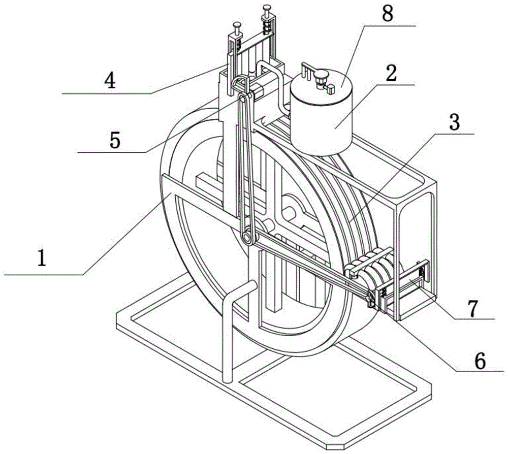
图1是本发明一种橡胶颗粒成型工艺的整体结构示意图;Fig. 1 is the overall structure schematic diagram of a kind of rubber particle molding process of the present invention;
图2是本发明定成型组件的结构示意图;Fig. 2 is the structural schematic diagram of the shaping component of the present invention;
图3是本发明导流注入组件的结构示意图;3 is a schematic structural diagram of the diversion injection assembly of the present invention;
图4是本发明动成型组件的结构示意图;4 is a schematic structural diagram of the dynamic forming assembly of the present invention;
图5是本发明柱塞组件的结构示意图;Fig. 5 is the structural representation of the plunger assembly of the present invention;
图6是本发明驱动组件的结构示意图;Fig. 6 is the structural representation of the drive assembly of the present invention;
图7是本发明出料组件的结构示意图;Fig. 7 is the structural representation of the discharging assembly of the present invention;
图8是本发明裁切组件的结构示意图;8 is a schematic structural diagram of the cutting assembly of the present invention;
图9是本发明混合组件的结构示意图。FIG. 9 is a schematic view of the structure of the mixing assembly of the present invention.
图中:定成型组件1;定支架101;定成型架102;定成型槽103;导出架104;导出管105;导流注入组件2;导流支架201;导流框202;导向架203;柱塞孔204;混合桶205;输出泵206;添加管207;动成型组件3;成型转轮301;成型输出轮302;成型输入轮303;输入齿形带304;输出齿形带305;柱塞组件4;柱塞连接板401;柱塞导向杆402;复位弹簧403;柱塞杆404;柱塞齿条405;驱动组件5;电机501;驱动缺齿齿轮502;驱动全齿齿轮503;出料组件6;出料转轮架601;出料转轮602;出料输入轮603;出料输出轮604;裁切组件7;裁切导向架701;裁切刀702;裁切弹簧703;裁切齿条704;混合组件8;盖801;加热炉802;连通管803;混合架804;混合电机805;混合叶轮806。In the figure: fixed forming
具体实施方式Detailed ways
下面结合附图对本发明作进一步详细说明。The present invention will be further described in detail below in conjunction with the accompanying drawings.
具体实施方式一:Specific implementation one:
下面结合图1-9说明本实施方式,一种橡胶颗粒成型工艺,包括以下步骤:步骤一:首先,将橡胶成型原料放置在混合容器中并在混合容器中充分混合;The present embodiment will be described below with reference to FIGS. 1-9, a rubber particle molding process, including the following steps: Step 1: First, the rubber molding raw materials are placed in a mixing container and fully mixed in the mixing container;
步骤二:其次,将混合后的原料加压添加到橡胶颗粒成型组件中成型出长条状材料;Step 2: secondly, the mixed raw materials are added under pressure into the rubber particle forming assembly to form long strips of material;
步骤三:最后,对长条形材料进行导出、切割和收集,实现橡胶颗粒的成型;Step 3: Finally, export, cut and collect the long strip material to realize the molding of rubber particles;
上述橡胶颗粒的成型工艺中还涉及一种橡胶颗粒成型装置;The above-mentioned rubber particle forming process also relates to a rubber particle forming device;
所述的橡胶颗粒成型装置,包括定成型组件1、导流注入组件2、动成型组件3、柱塞组件4、驱动组件5、出料组件6、裁切组件7和混合组件8,其特征在于:所述导流注入组件2固定连接在定成型组件1上,动成型组件3转动连接在定成型组件1上,柱塞组件4滑动连接在导流注入组件2上,驱动组件5固定连接在导流注入组件2上,驱动组件5和柱塞组件4啮合传动,驱动组件5和动成型组件3带传动,出料组件6和裁切组件7均固定连接在定成型组件1上,出料组件6和裁切组件7啮合传动,驱动组件5和出料组件6带传动,混合组件8通过螺栓可拆卸连接在导流注入组件2上。The rubber particle forming device includes a fixed forming
通过混合组件8对橡胶成型原料进行融化和混合,为橡胶颗粒的成型提供原料,还可以通过驱动组件5啮合驱动柱塞组件4升降,实现将导流注入组件2内的原料加压添加到定成型组件1和动成型组件3之间进行成型,再通过驱动组件5带动动成型组件3转动实现成型橡胶的自动出料和为原料的持续成型提供空间,再通过动成型组件3带动出料组件6转动实现出料组件6带动成型的橡胶进行出料,再通过出料组件6啮合驱动裁切组件7实现裁切组件7对成型的橡胶进行切割获得橡胶颗粒,实现橡胶颗粒的快速成型。The rubber molding raw materials are melted and mixed by the
具体实施方式二:Specific implementation two:
下面结合图1-9说明本实施方式,所述定成型组件1包括定支架101、定成型架102、定成型槽103、导出架104和导出管105,定成型架102固定连接在定支架101上,定成型架102上均布有多个定成型槽103,导出架104固定连接在定成型架102的右端,导出架104上均布有多个导出管105,多个导出管105和多个定成型槽103一一对应,定成型架102由耐磨材料制成,多个定成型槽103均经过抛光处理,达到橡胶不易粘连的效果,防止成型时橡胶粘连在定成型槽103内,无法持续性实现橡胶的成型。The present embodiment will be described below with reference to FIGS. 1-9 . The shaping
具体实施方式三:Specific implementation three:
下面结合图1-9说明本实施方式,所述导流注入组件2包括导流支架201、导流框202、导向架203、柱塞孔204、混合桶205、输出泵206和添加管207,导流支架201固定连接在定支架101上,导流框202固定连接在导流支架201上,导流框202的前后两侧均固定连接有导向架203,导流框202内均布有多个柱塞孔204,混合桶205固定连接在导流支架201上,混合桶205上固定连接有添加管207,添加管207上设置有输出泵206,多个柱塞孔204分别和多个定成型槽103一一对应。The present embodiment will be described below with reference to FIGS. 1-9 . The
具体实施方式四:Specific implementation four:
下面结合图1-9说明本实施方式,所述动成型组件3包括成型转轮301、成型输出轮302、成型输入轮303、输入齿形带304和输出齿形带305,成型转轮301转动连接在定支架101上,成型转轮301上设置有成型输出轮302和成型输入轮303,成型转轮301上设置有多个转动成型槽,多个转动成型槽分别和多个定成型槽103一一对应,成型转轮301的表面比定成型架102的表面粗糙,可以实现成型转轮301带动成型后的橡胶转动,实现成型好的橡胶的不断运输,使得橡胶可以不断的成型。The present embodiment will be described below with reference to FIGS. 1-9. The dynamic forming
具体实施方式五:Specific implementation five:
下面结合图1-9说明本实施方式,所述柱塞组件4包括柱塞连接板401、柱塞导向杆402、复位弹簧403、柱塞杆404和柱塞齿条405,柱塞连接板401上固定连接有两个柱塞导向杆402,两个柱塞导向杆402分别滑动连接在两个导向架203上,两个导向架203和柱塞连接板401之间均设置有复位弹簧403,柱塞连接板401上固定连接有多个柱塞杆404,柱塞连接板401的前端固定连接有柱塞齿条405。The present embodiment will be described below with reference to FIGS. 1-9 . The
具体实施方式六:Specific implementation six:
下面结合图1-9说明本实施方式,所述驱动组件5包括电机501、驱动缺齿齿轮502和驱动全齿齿轮503,电机501固定连接在导流框202上,电机501的输出轴上固定连接有驱动缺齿齿轮502和驱动全齿齿轮503,驱动缺齿齿轮502和柱塞齿条405啮合传动,成型输入轮303和驱动全齿齿轮503通过输入齿形带304传动。The present embodiment will be described below with reference to FIGS. 1-9 . The driving
具体实施方式七:Specific implementation seven:
下面结合图1-9说明本实施方式,所述出料组件6包括出料转轮架601、出料转轮602、出料输入轮603和出料输出轮604,两个出料转轮架601均固定连接在定成型架102上,出料转轮602转动连接在出料转轮架601上,出料输入轮603固定连接在出料转轮602上,出料输入轮603和成型输出轮302通过输出齿形带305传动。The present embodiment will be described below with reference to Figs. 1-9. The
具体实施方式八:Eighth specific implementation:
下面结合图1-9说明本实施方式,所述裁切组件7包括裁切导向架701、裁切刀702、裁切弹簧703和裁切齿条704,裁切导向架701固定连接在定成型架102上,裁切刀702滑动连接在裁切导向架701上,裁切导向架701和裁切刀702的上端之间设置有两个裁切弹簧703,裁切刀702的前后两侧均固定连接有裁切齿条704,两个裁切齿条704分别和两个出料输出轮604啮合传动。1-9, the cutting
具体实施方式九:Specific implementation nine:
下面结合图1-9说明本实施方式,所述混合组件8包括盖801、加热炉802、连通管803、混合架804、混合电机805和混合叶轮806,盖801通过螺栓可拆卸连接在混合桶205上,盖801上设置有加热炉802,加热炉802上设置有连通管803,混合架804固定连接在盖801上,混合电机805固定连接在混合架804上,混合叶轮806固定连接在混合电机805的输出轴,混合叶轮806转动连接在连通管803上。1-9, the mixing
具体实施方式十:Specific implementation ten:
下面结合图1-9说明本实施方式,采用上述的一种橡胶颗粒成型工艺制成的橡胶颗粒,该橡胶颗粒由以下重量份数的原料组成:乙丙橡胶15份;碳酸钙40份;交联剂6份;过氧化物硫化剂8份;石蜡油15份;颜料6份;柠檬香精5份。The present embodiment will be described below with reference to Figures 1-9, and the rubber particles made by the above-mentioned rubber particle molding process are made up of the following raw materials by weight: 15 parts of ethylene-propylene rubber; 40 parts of calcium carbonate; 6 parts of joint agent; 8 parts of peroxide curing agent; 15 parts of paraffin oil; 6 parts of pigment; 5 parts of lemon essence.
本发一种橡胶颗粒成型工艺,其使用原理为:盖801上设置有进料孔,将原料通过盖801上的进料孔添加进混合桶205内,启动加热炉802,加热炉802内的高温气体流进连通管803内,再流进混合叶轮806加热,启动混合电机805,混合电机805带动混合叶轮806转动,混合叶轮806带动原料进行转动,同时,高温的混合叶轮806对原料进行加热,使得原料进行融化,启动输出泵206,输出泵206将混合桶205内的融化的原料泵进添加管207内,原料再通过多个柱塞孔204流进多个定成型槽103内,启动电机501,电机501带动驱动缺齿齿轮502转动,驱动缺齿齿轮502啮合驱动柱塞齿条405滑动,柱塞齿条405带动柱塞连接板401下降,柱塞连接板401带动多个柱塞杆404下降将原料加压注入进多个定成型槽103和成型转轮301的成型槽内,柱塞连接板401带动两个复位弹簧403拉伸,当驱动缺齿齿轮502与柱塞齿条405失去啮合的时候,被拉伸的两个复位弹簧403带动柱塞连接板401上升,实现多个柱塞杆404的复位,柱塞杆404的往复运动实现不停的对融化的原料加压注入到多个柱塞孔204内,驱动全齿齿轮503带动输入齿形带304转动,输入齿形带304带动成型输入轮303转动,成型输入轮303带动成型转轮301转动,融化的原料流进多个定成型槽103和成型转轮301的成型槽内,成型出圆柱长条形的橡胶长条,成型转轮301的转动带动成型的橡胶不断的转动输出,成型转轮301带动成型输出轮302转动,成型输出轮302带动输出齿形带305转动,输出齿形带305带动出料输入轮603转动,出料输入轮603带动出料转轮602转动,将成型的多个橡胶再通过多个导出管105导出,将多个成型后的橡胶放置在出料转轮602的下端压紧,出料转轮602的转动带动多个橡胶不停的输出,出料转轮602带动两个出料输入轮603转动,两个出料输入轮603啮合驱动裁切齿条704滑动,两个裁切齿条704的滑动带动两个裁切刀702滑动对成型的橡胶进行切割实现橡胶颗粒的加工,裁切刀702的下降压缩两个裁切弹簧703,当两个出料输入轮603和两个裁切齿条704失去啮合的时候,被压缩的两个裁切弹簧703推动裁切刀702复位,裁切刀702的往复升降实现对成型橡胶的不断裁切,完成橡胶颗粒的加工。The present invention is a rubber granule molding process, and its use principle is as follows: the
当然,上述说明并非对本发明的限制,本发明也不仅限于上述举例,本技术领域的普通技术人员在本发明的实质范围内所做出的变化、改型、添加或替换,也属于本发明的保护范围。Of course, the above description does not limit the present invention, and the present invention is not limited to the above examples. Changes, modifications, additions or substitutions made by those of ordinary skill in the art within the essential scope of the present invention also belong to the present invention. protected range.
Claims (2)
Priority Applications (1)
| Application Number | Priority Date | Filing Date | Title |
|---|---|---|---|
| CN202011258828.9A CN112476830B (en) | 2020-11-12 | 2020-11-12 | Rubber particle forming process and rubber particles |
Applications Claiming Priority (1)
| Application Number | Priority Date | Filing Date | Title |
|---|---|---|---|
| CN202011258828.9A CN112476830B (en) | 2020-11-12 | 2020-11-12 | Rubber particle forming process and rubber particles |
Publications (2)
| Publication Number | Publication Date |
|---|---|
| CN112476830A CN112476830A (en) | 2021-03-12 |
| CN112476830B true CN112476830B (en) | 2022-08-09 |
Family
ID=74929843
Family Applications (1)
| Application Number | Title | Priority Date | Filing Date |
|---|---|---|---|
| CN202011258828.9A Active CN112476830B (en) | 2020-11-12 | 2020-11-12 | Rubber particle forming process and rubber particles |
Country Status (1)
| Country | Link |
|---|---|
| CN (1) | CN112476830B (en) |
Families Citing this family (1)
| Publication number | Priority date | Publication date | Assignee | Title |
|---|---|---|---|---|
| CN114932227A (en) * | 2022-05-28 | 2022-08-23 | 王楠 | Preparation method of powder metallurgy material |
Citations (6)
| Publication number | Priority date | Publication date | Assignee | Title |
|---|---|---|---|---|
| JP2004131641A (en) * | 2002-10-11 | 2004-04-30 | Mitsubishi Engineering Plastics Corp | Colored masterbatch for polyacetal resin, polyacetal resin composition containing the same, and molded article |
| JP2010188283A (en) * | 2009-02-18 | 2010-09-02 | Kawata Mfg Co Ltd | Cyclone device and fine powder removal method |
| JP2018140344A (en) * | 2017-02-27 | 2018-09-13 | 有限会社長崎糧機 | Separation device of granular material, air and foreign matter |
| CN109706072A (en) * | 2019-01-24 | 2019-05-03 | 王静 | A kind of microbe immobilized particles preparation facilities |
| CN208946432U (en) * | 2018-10-17 | 2019-06-07 | 天津市聚晶婕科技发展有限责任公司 | A kind of molding equipment for plastic grain |
| CN110465240A (en) * | 2019-09-04 | 2019-11-19 | 于玮 | A compound fertilizer granulation equipment |
Family Cites Families (11)
| Publication number | Priority date | Publication date | Assignee | Title |
|---|---|---|---|---|
| GB548206A (en) * | 1941-03-25 | 1942-09-30 | Holland & Hannen And Cubitts L | Improvements in or relating to the foaming or granulation of molten material |
| DE1916230A1 (en) * | 1969-03-29 | 1972-02-24 | Schmitz Rolf Guenther | Granulation of high melting pt materials - by impact dispersion |
| JPS52125472A (en) * | 1976-04-15 | 1977-10-21 | Matsushita Electric Works Ltd | Pelletizer |
| JPH069821B2 (en) * | 1987-10-23 | 1994-02-09 | 正夫 森山 | Pellet manufacturing equipment |
| CA2314921A1 (en) * | 2000-08-03 | 2002-02-03 | Barry Partington | Apparatus and method for producing porous polymer particles |
| JP6010816B2 (en) * | 2012-07-31 | 2016-10-19 | 宇部興産機械株式会社 | Horizontal screw silo and cargo carrier equipped with the same |
| CH707660A1 (en) * | 2013-02-26 | 2014-08-29 | Bp Recycling Systems Gmbh | Pelleting or granulating. |
| CN109679229A (en) * | 2017-10-19 | 2019-04-26 | 上海涛瀚橡塑制品有限公司 | A kind of rubber grain and preparation method thereof |
| CN110665433B (en) * | 2019-10-24 | 2022-03-01 | 河南农业大学 | Tobacco rod biomass pellet fuel forming granulator |
| CN111792398A (en) * | 2020-07-10 | 2020-10-20 | 章庆聪 | Particulate matter preparation device |
| CN111841443A (en) * | 2020-07-20 | 2020-10-30 | 王凤财 | Cylindrical rolling type granulator capable of screening uniform particles |
-
2020
- 2020-11-12 CN CN202011258828.9A patent/CN112476830B/en active Active
Patent Citations (6)
| Publication number | Priority date | Publication date | Assignee | Title |
|---|---|---|---|---|
| JP2004131641A (en) * | 2002-10-11 | 2004-04-30 | Mitsubishi Engineering Plastics Corp | Colored masterbatch for polyacetal resin, polyacetal resin composition containing the same, and molded article |
| JP2010188283A (en) * | 2009-02-18 | 2010-09-02 | Kawata Mfg Co Ltd | Cyclone device and fine powder removal method |
| JP2018140344A (en) * | 2017-02-27 | 2018-09-13 | 有限会社長崎糧機 | Separation device of granular material, air and foreign matter |
| CN208946432U (en) * | 2018-10-17 | 2019-06-07 | 天津市聚晶婕科技发展有限责任公司 | A kind of molding equipment for plastic grain |
| CN109706072A (en) * | 2019-01-24 | 2019-05-03 | 王静 | A kind of microbe immobilized particles preparation facilities |
| CN110465240A (en) * | 2019-09-04 | 2019-11-19 | 于玮 | A compound fertilizer granulation equipment |
Also Published As
| Publication number | Publication date |
|---|---|
| CN112476830A (en) | 2021-03-12 |
Similar Documents
| Publication | Publication Date | Title |
|---|---|---|
| CN112476830B (en) | Rubber particle forming process and rubber particles | |
| CN114887727A (en) | Extraction and purification equipment and method for liver-protecting lonicera edulis polysaccharide | |
| CN215969810U (en) | Plastic mold with controllable quantitative injection molding mechanism | |
| CN107627583A (en) | A kind of plastic processing material-extruding machine | |
| CN117140777A (en) | A plastic product granulation device and process | |
| CN117861516A (en) | Fertilizer preparation equipment for landscaping and preparation method thereof | |
| CN110813217A (en) | Polyurethane resin's sealed reation kettle | |
| CN109501035A (en) | A kind of polybag processing plastic grain thawing apparatus | |
| CN212764301U (en) | Vulcanization equipment of patterned conveying belt | |
| CN112706383A (en) | Screw extruder is used in plastics processing | |
| CN112110556A (en) | Energy-saving central water treatment facilities | |
| CN216172373U (en) | Retort for chemical production of intelligence accuse temperature | |
| CN118477532A (en) | Hot melt adhesive molten material stirring device and method | |
| CN215703187U (en) | Plastic crushing device for plastic processing | |
| CN110948724A (en) | A novel blendor for producing RCPP membrane of cooking | |
| CN216295818U (en) | Storage tank for phenolic resin production | |
| CN215963149U (en) | Preparation mechanism of high-temperature easily-hydrolyzed UV glue with good metal adhesion | |
| CN113842690A (en) | Filtering device for processing synthetic resin material | |
| CN215750210U (en) | Device for treating waste plastics | |
| CN116900316A (en) | A metal injection molding device with self-cleaning function | |
| CN214448239U (en) | Rubber injection molding machine with material mixing function | |
| CN111602835A (en) | A composite type of high-efficiency bar-making equipment for food processing | |
| CN221016020U (en) | Backflow preventing device for cadmium-free quantum dot preparation | |
| CN114192048A (en) | Edible mushroom raw material stirring device and method easy to discharge | |
| CN106390801A (en) | Vacuum kneader, with filtering device, for silica gel |
Legal Events
| Date | Code | Title | Description |
|---|---|---|---|
| PB01 | Publication | ||
| PB01 | Publication | ||
| SE01 | Entry into force of request for substantive examination | ||
| SE01 | Entry into force of request for substantive examination | ||
| TA01 | Transfer of patent application right |
Effective date of registration: 20220714 Address after: 110032 a1-4-1, No. 52, Nenjiang street, Huanggu District, Shenyang City, Liaoning Province Applicant after: Zhao Qian Address before: 150300 Room 101, unit 2, Zhengyi community, 627 Yanchuan street, Acheng District, Harbin City, Heilongjiang Province Applicant before: Zhu Peng |
|
| TA01 | Transfer of patent application right | ||
| GR01 | Patent grant | ||
| GR01 | Patent grant | ||
| TR01 | Transfer of patent right | ||
| TR01 | Transfer of patent right |
Effective date of registration: 20221212 Address after: No. 912-D01, No. 462, Qingnian South Road, Zhifu District, Yantai City, Shandong Province, 264000 Patentee after: Yantai Yulan Yaxin Technology Service Center Address before: 110032 a1-4-1, No. 52, Nenjiang street, Huanggu District, Shenyang City, Liaoning Province Patentee before: Zhao Qian |
|
| TR01 | Transfer of patent right |
Effective date of registration: 20221228 Address after: 130062 Xi Xin Zhen Pei Jia Cun Xiao Zheng Jia Tun, Luyuan District, Changchun City, Jilin Province Patentee after: CHANGCHUN SHIFA TECHNOLOGY CO.,LTD. Address before: No. 912-D01, No. 462, Qingnian South Road, Zhifu District, Yantai City, Shandong Province, 264000 Patentee before: Yantai Yulan Yaxin Technology Service Center |
|
| TR01 | Transfer of patent right | ||
| PE01 | Entry into force of the registration of the contract for pledge of patent right |
Denomination of invention: A rubber particle forming process and rubber particles Effective date of registration: 20230713 Granted publication date: 20220809 Pledgee: China Construction Bank Co.,Ltd. Changchun Science and Technology Sub branch Pledgor: CHANGCHUN SHIFA TECHNOLOGY CO.,LTD. Registration number: Y2023220000052 |
|
| PE01 | Entry into force of the registration of the contract for pledge of patent right | ||
| PC01 | Cancellation of the registration of the contract for pledge of patent right |
Granted publication date: 20220809 Pledgee: China Construction Bank Co.,Ltd. Changchun Science and Technology Sub branch Pledgor: CHANGCHUN SHIFA TECHNOLOGY CO.,LTD. Registration number: Y2023220000052 |
|
| PC01 | Cancellation of the registration of the contract for pledge of patent right | ||
| PE01 | Entry into force of the registration of the contract for pledge of patent right |
Denomination of invention: A rubber particle molding process and rubber particles Granted publication date: 20220809 Pledgee: China Construction Bank Co.,Ltd. Changchun Science and Technology Sub branch Pledgor: CHANGCHUN SHIFA TECHNOLOGY CO.,LTD. Registration number: Y2025220000029 |
|
| PE01 | Entry into force of the registration of the contract for pledge of patent right |