Detailed Description
Hereinafter, embodiments of the present invention will be described in detail with reference to the drawings.
Example 1
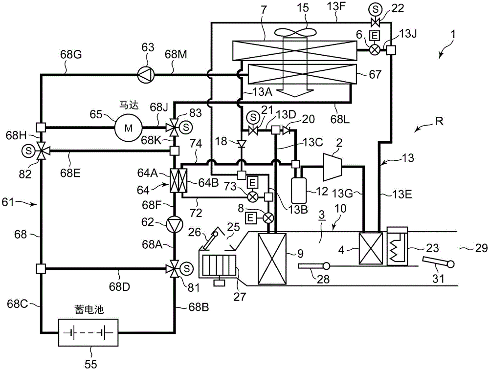
Fig. 1 shows a configuration diagram of a vehicle air conditioner 1 to which an embodiment of the present invention is applied. A vehicle to which an embodiment of the present invention is applied is an Electric Vehicle (EV) not equipped with an engine (internal combustion engine), and the vehicle is equipped with a battery 55 (for example, a lithium battery), and travels by supplying electric power charged in the battery 55 from an external power supply to a travel motor (electric motor) 65 to drive the same. The vehicle air conditioner 1 is also driven by being supplied with power from the battery 55.
That is, in the air conditioner 1 for a vehicle, in the electric vehicle in which the heating by the engine waste heat cannot be performed, the air conditioning is performed in the vehicle interior by performing the heating operation by the heat pump operation using the refrigerant circuit R and by selectively performing each of the air conditioning operations of the dehumidification heating operation, the dehumidification cooling operation, and the cooling operation.
The heating operation and the dehumidifying heating operation are air-conditioning operations for heating the vehicle interior of the present invention, and the cooling operation and the dehumidifying cooling operation are air-conditioning operations for cooling the vehicle interior of the present invention. It is needless to say that the present invention is also effective in a so-called hybrid vehicle in which an engine and an electric motor for running are used in combination, as the vehicle, not limited to the electric vehicle described above.
An air conditioning apparatus 1 for a vehicle according to an embodiment performs air conditioning (heating, cooling, dehumidification, and ventilation) of an interior of an electric vehicle, and in the air conditioning apparatus 1 for a vehicle, an electric compressor (electric compressor) 2, a radiator 4, an outdoor expansion valve 6, an outdoor heat exchanger 7, an indoor expansion valve 8, a heat absorber 9, an accumulator 12, and the like are connected in this order by refrigerant pipes 13 to form a refrigerant circuit R, wherein the compressor 2 compresses a refrigerant, the radiator 4 is provided in an air flow path 3 of an HVAC unit 10 that supplies an air ventilation cycle of the interior of the vehicle, a high-temperature and high-pressure refrigerant discharged from the compressor 2 is caused to flow in via a refrigerant pipe 13G and is caused to radiate heat therefrom to heat air supplied to the interior of the vehicle, and the outdoor expansion valve 6 decompresses and expands the refrigerant during heating and is constituted by an electric valve, the outdoor heat exchanger 7 is for exchanging heat between the refrigerant and the outside air to function as a radiator (condenser) for radiating the refrigerant during cooling and as an evaporator for absorbing heat from the refrigerant during heating, the indoor expansion valve 8 is configured by an electrically operated valve for decompressing and expanding the refrigerant, and the heat absorber 9 is provided in the air flow path 3 and is for absorbing heat from the inside and outside of the vehicle cabin to cool the air supplied into the vehicle cabin during cooling (during dehumidification). The outdoor expansion valve 6 and the indoor expansion valve 8 can be fully opened or fully closed while reducing the pressure of and expanding the refrigerant.
Further, an outdoor fan 15 is provided in the outdoor heat exchanger 7. The outdoor fan 15 is configured to forcibly ventilate the outdoor air to the outdoor heat exchanger 7 to exchange heat between the outdoor air and the refrigerant, and thereby ventilate the outdoor air to the outdoor heat exchanger 7 even during a stop (i.e., a vehicle speed of 0 km/h).
The refrigerant pipe 13A connected to the refrigerant outlet side of the outdoor heat exchanger 7 is connected to the refrigerant pipe 13B via a check valve 18. The check valve 18 is disposed clockwise on the refrigerant pipe 13B side, and the refrigerant pipe 13B is connected to the indoor expansion valve 8.
The refrigerant pipe 13A extending from the outdoor heat exchanger 7 branches, and the branched refrigerant pipe 13D is connected to the refrigerant pipe 13C on the outlet side of the heat absorber 9 via the solenoid valve 21 opened during heating. A check valve 20 is connected to the refrigerant pipe 13C on the downstream side of the connection point of the refrigerant pipe 13D, the refrigerant pipe 13C on the downstream side of the check valve 20 is connected to the accumulator 12, and the accumulator 12 is connected to the refrigerant suction side of the compressor 2. The check valve 20 is disposed clockwise on the tank 12 side.
The refrigerant pipe 13E on the outlet side of the radiator 4 is branched into a refrigerant pipe 13J and a refrigerant pipe 13F in front of (on the refrigerant upstream side of) the outdoor expansion valve 6, and the branched refrigerant pipe 13J is connected to the refrigerant inlet side of the outdoor heat exchanger 7 via the outdoor expansion valve 6. The other refrigerant pipe 13F branched therefrom is connected to the refrigerant pipe 13B located on the refrigerant downstream side of the check valve 18 and on the refrigerant upstream side of the indoor expansion valve 8 via the solenoid valve 22 opened during dehumidification.
Thus, the refrigerant pipe 13F is connected in parallel to the series circuit of the outdoor expansion valve 6, the outdoor heat exchanger 7, and the check valve 18, and becomes a bypass circuit that bypasses the outdoor expansion valve 6, the outdoor heat exchanger 7, and the check valve 18.
Further, an air flow path 3 on the air upstream side of the heat absorber 9 is formed with suction ports (a suction port 25 is representatively shown in fig. 1) of an external air suction port and an internal air suction port, and a suction switching damper 26 is provided at the suction port 25, and the suction switching damper 26 switches the air introduced into the air flow path 3 between internal air (internal air circulation) which is air in the vehicle interior and external air (external air introduction) which is air outside the vehicle interior. Further, an indoor blower (blower fan) 27 is provided on the air downstream side of the suction switching damper 26, and the indoor blower 27 is configured to send the introduced internal air or external air to the air flow path 3.
In fig. 1, reference numeral 23 denotes an auxiliary heater as an auxiliary heating device. In the embodiment, the auxiliary heater 23 is constituted by a PTC heater (electric heater), and is provided in the air flow path 3 on the air downstream side of the heat sink 4 with respect to the flow of air in the air flow path 3. When the auxiliary heater 23 is energized to generate heat, it serves as a so-called heater core to supplement heating in the vehicle interior.
An air mixing damper 28 is provided in the air flow path 3 on the air upstream side of the radiator 4, and the air mixing damper 28 adjusts the ratio of air (internal air or external air) flowing into the air flow path 3 and passing through the heat absorber 9 in the air flow path 3 to be ventilated to the radiator 4 and the auxiliary heater 23. Further, the air flow path 3 on the air downstream side of the radiator 4 is formed with blow-out ports (representatively shown as a blow-out port 29 in fig. 1) of a blow-out leg (japanese: フット), a natural wind (japanese: ベント), and a front windshield defogging (japanese: デフ), and the blow-out port switching flap 31 is provided in the blow-out port 29, and the blow-out port switching flap 31 switches and controls the blow-out of air from the blow-out ports.
The air conditioner 1 for a vehicle includes a device temperature control device 61, and the device temperature control device 61 circulates a heat medium to the battery 55 and the travel motor 65 to control the temperatures of the battery 55 and the travel motor 65. That is, in the embodiment, the traveling motor 65 is a predetermined temperature-controlled object other than the battery 55 mounted on the vehicle. The concept of the traveling motor 65 as the temperature controlled object of the present invention is not limited to the electric motor itself, and includes electric devices such as an inverter circuit for driving the electric motor. It is needless to say that a device that is mounted on the vehicle and generates heat other than the traveling motor 65 can be used as the temperature controlled object.
The device temperature adjusting apparatus 61 of the present embodiment includes: a first circulation pump 62 and a second circulation pump 63, the first circulation pump 62 and the second circulation pump 63 serving as circulation means for circulating the heat medium to the battery 55 and the travel motor 65; a refrigerant-heat medium heat exchanger 64; an air-heat medium heat exchanger 67; and a first three-way valve 81, a second three-way valve 82, and a third three-way valve 83 as flow path switching devices, which are connected to the battery 55 and the travel motor 65 via the heat medium piping 68.
In the present embodiment, a heat medium pipe 68A is connected to the discharge side of the first circulation pump 62, and the heat medium pipe 68A is connected to the inlet of the first three-way valve 81. One outlet of the first three-way valve 81 is connected to a heat medium pipe 68B, and the heat medium pipe 68B is connected to an inlet of the battery 55. The outlet of the battery 55 is connected to a heat medium pipe 68C, and the heat medium pipe 68C is connected to the inlet of the second three-way valve 82. The other outlet of the first three-way valve 81 is connected to a heat medium pipe 68D, and the heat medium pipe 68D is connected to a heat medium pipe 68C between the battery 55 and the second three-way valve 82. Thereby, the heat medium pipe 68D is configured to bypass the battery 55.
One outlet of the second three-way valve 82 is connected to a heat medium pipe 68E, and the heat medium pipe 68E is connected to an inlet of the heat medium flow path 64A of the refrigerant-heat medium heat exchanger 64. A heat medium pipe 68F is connected to an outlet of the heat medium flow path 64A, and the heat medium pipe 68F is connected to a suction side of the first circulation pump 62.
On the other hand, a heat medium pipe 68G is connected to the discharge side of the second circulation pump 63, and the heat medium pipe 68G is connected to the inlet of the travel motor 65. The other outlet of the second three-way valve 82 is connected to a heat medium pipe 68H, and the heat medium pipe 68H is connected to a heat medium pipe 68G between the second circulation pump 63 and the traveling motor 65. The outlet of the traveling motor 65 is connected to a heat medium pipe 68J, and the heat medium pipe 68J is connected to the inlet of the third three-way valve 83.
One outlet of the third three-way valve 83 is connected to a heat medium pipe 68K, and the heat medium pipe 68K is connected to a heat medium pipe 68E between the second three-way valve 82 and the refrigerant-heat medium heat exchanger 64. The other outlet of the third three-way valve 83 is connected to a heat medium pipe 68L, and the heat medium pipe 68L is connected to the inlet of the air-heat medium heat exchanger 67. A heat medium pipe 68M is connected to an outlet of the air-heat medium heat exchanger 67, and the heat medium pipe 68M is connected to a suction side of the second circulation pump 63.
As the heat medium used in the above-described equipment temperature control device 61, for example, water, a refrigerant such as HFO-1234yf, a liquid such as a coolant, or a gas such as air can be used. In addition, in the embodiment, water is used as the heat medium. Further, for example, a sleeve structure in which a heat medium can flow in a heat exchange relationship with the battery 55 and the travel motor 65 is provided around the battery 55 and the travel motor 65. The air-heat medium heat exchanger 67 is disposed downstream of the outdoor heat exchanger 7 with respect to the flow (air passage) of the outside air (air) blown by the outdoor fan 15.
When the first circulation pump 62 is operated in a state where the first three-way valve 81 has the inlet connected to the other outlet, the second three-way valve 82 has the inlet connected to the other outlet, and the third three-way valve 83 has the inlet connected to the one outlet, the heat medium discharged from the first circulation pump 62 flows through the heat medium pipe 64A, the first three-way valve 81, the heat medium pipe 68D, the heat medium pipe 68C, the second three-way valve 82, the heat medium pipe 68H, the heat medium pipe 68G, the traveling motor 65, the heat medium pipe 68J, the third three-way valve 83, the heat medium pipe 68K, the heat medium pipe 68E, the heat medium flow passage 64A of the refrigerant-heat medium heat exchanger 64, and the heat medium pipe 68F in this order, and is sucked into the first circulation pump 62. The above state is set as a first flow path control state.
In the first flow path control state, as will be described later, the heat medium cooled by the heat absorbed by the refrigerant in the heat medium flow path 64A of the refrigerant-heat medium heat exchanger 64 circulates to the travel motor 65, exchanges heat with the travel motor 65, recovers waste heat from the travel motor 65, and cools the travel motor 65 itself. On the other hand, the heat medium is not circulated to the battery 55, and therefore, the battery 55 is not cooled by the heat medium.
Next, when the first circulation pump 62 and the second circulation pump 63 are operated while switching to a state in which the first three-way valve 81 connects the inlet to one outlet, the second three-way valve 82 connects the inlet to one outlet, and the third three-way valve 83 connects the inlet to the other outlet, the heat medium discharged from the first circulation pump 62 flows through the heat medium pipe 64A, the first three-way valve 81, the heat medium pipe 68B, the battery 55, the heat medium pipe 68C, the second three-way valve 82, the heat medium pipe 68E, the heat medium flow path 64A of the refrigerant-heat medium heat exchanger 64, and the heat medium pipe 68F in this order, and is sucked into the first circulation pump 62. On the other hand, the heat medium discharged from the second circulation pump 63 flows through the heat medium pipe 68G, the traveling motor 65, the heat medium pipe 68J, the third three-way valve 83, the heat medium pipe 68L, the air-heat medium heat exchanger 67, and the heat medium pipe 68M in this order, and is circulated and sucked into the second circulation pump 63. The above state is set as the second flow path control state.
In the second flow path control state, the heat medium circulates between the battery 55 and the refrigerant-heat medium heat exchanger 64. Therefore, as will be described later, the heat medium cooled by the heat absorbed by the refrigerant in the heat medium flow path 64A of the refrigerant-heat medium heat exchanger 64 circulates to the battery 55, and exchanges heat with the battery 55 to cool the battery 55. The heat medium is circulated between the travel motor 65 and the air-heat medium heat exchanger 67. Therefore, the heat medium cooled (air-cooled) by the outside air in the air-heat medium heat exchanger 67 circulates to the travel motor 65, and exchanges heat with the travel motor 65 to cool the travel motor 65.
On the other hand, one end of a branch pipe 72 as a branch circuit is connected to the refrigerant pipe 13B located on the refrigerant downstream side of the connection between the refrigerant pipe 13F and the refrigerant pipe 13B, which is the outlet of the refrigerant pipe 13F of the refrigerant circuit R, and on the refrigerant upstream side of the indoor expansion valve 8. The branch pipe 72 is provided with an auxiliary expansion valve 73 formed of an electrically operated valve. The auxiliary expansion valve 73 may be fully closed while decompressing and expanding the refrigerant flowing into the refrigerant flow path 64B of the refrigerant-heat medium heat exchanger 64, which will be described later.
The other end of the branch pipe 72 is connected to the refrigerant flow path 64B of the refrigerant-heat medium heat exchanger 64, one end of a refrigerant pipe 74 is connected to an outlet of the refrigerant flow path 64B, and the other end of the refrigerant pipe 74 is connected to a refrigerant pipe 13C located on the refrigerant downstream side of the check valve 20 and in the vicinity of the accumulator 12 (on the refrigerant upstream side). These auxiliary expansion valves 73 and the like also constitute a part of the refrigerant circuit R and also constitute a part of the device temperature adjusting apparatus 61.
When the auxiliary expansion valve 73 is opened, the refrigerant (a part or all of the refrigerant) flowing out of the refrigerant pipe 13F and the outdoor heat exchanger 7 flows into the branch pipe 27, is reduced in pressure by the auxiliary expansion valve 73, then flows into the refrigerant flow path 64B of the refrigerant-heat medium heat exchanger 64, and is evaporated there. While flowing through the refrigerant flow path 64B, the refrigerant absorbs heat from the heat medium flowing through the heat medium flow path 64A, and is then drawn into the compressor 2 through the accumulator 12.
Next, in fig. 2, reference numeral 32 denotes an air conditioner controller 32 as a control device which is responsible for controlling the vehicle air conditioner 1. The air conditioning controller 32 is connected to a vehicle controller 35(ECU) that controls the entire vehicle, including driving control of the traveling motor 65 and charging and discharging control of the battery 55, via a vehicle communication bus 45, and is configured to receive and transmit information. Each of the air conditioning controller 32 and the vehicle controller 35(ECU) is constituted by a microcomputer as an example of a computer including a processor.
Input of the air conditioner controller 32 (control device), and an outside air temperature sensor 33, an outside air humidity sensor 34, an HVAC intake temperature sensor 36, an inside air temperature sensor 37, an inside air humidity sensor 38, and indoor CO2Outputs of a concentration sensor 39, an outlet temperature sensor 41, an outlet pressure sensor 42, an outlet temperature sensor 43, an intake temperature sensor 44, a radiator temperature sensor 46, a radiator pressure sensor 47, a heat absorber temperature sensor 48, a heat absorber pressure sensor 49, for example, a photo-sensor type insolation sensor 51, a vehicle speed sensor 52, an air-conditioning operation unit 53, an outdoor heat exchanger temperature sensor 54, and an outdoor heat exchanger pressure sensor 56 are connected, wherein the outside air temperature sensor 33 detects an outside air temperature (Tam) of the vehicle, the outside air humidity sensor 34 detects an outside air humidity, the HVAC intake temperature sensor 36 detects a temperature of air taken in from the intake port 25 to the air flow path 3, and the inside air temperature sensor 37 detects a temperature of air (inside air) in the vehicle interior, the internal air humidity sensor 38 detects the humidity of the air in the vehicle interior, i.e., the interior CO2A concentration sensor 39 detects the concentration of carbon dioxide in the vehicle interior, the outlet temperature sensor 41 detects the temperature of air blown out from the outlet port 29 into the vehicle interior, the outlet pressure sensor 42 detects the pressure of the discharged refrigerant (outlet pressure Pd) of the compressor 2, the outlet temperature sensor 43 detects the temperature of the discharged refrigerant of the compressor 2, the inlet temperature sensor 44 detects the temperature of the sucked refrigerant of the compressor 2, the radiator temperature sensor 46 detects the temperature of the radiator 4 (the temperature of air passing through the radiator 4 or the temperature of the radiator 4 itself: radiator temperature TCI), the radiator pressure sensor 47 detects the pressure of the refrigerant of the radiator 4 (the pressure of the refrigerant in the radiator 4 or immediately after flowing out from the radiator 4: radiator pressure PCI), the heat absorber temperature sensor 48 absorbs the temperature of the heat absorber 9 (absorbs heat therefrom)Temperature of air of the container 9 or temperature of the heat absorber 9 itself: heat absorber temperature Te), the heat absorber pressure sensor 49 detects the refrigerant pressure of the heat absorber 9 (the pressure of the refrigerant inside the heat absorber 9 or just flowing out of the heat absorber 9), the insolation sensor 51 detects the amount of insolation inside the vehicle compartment, the vehicle speed sensor 52 detects the traveling speed of the vehicle (vehicle speed), the air-conditioning operation unit 53 sets the set temperature and the switching of the air-conditioning operation, and the outdoor heat exchanger temperature sensor 54 detects the temperature of the outdoor heat exchanger 7 (the temperature of the refrigerant just flowing out of the outdoor heat exchanger 7 or the temperature of the outdoor heat exchanger 7 itself: outdoor heat exchanger temperature TXO. When the outdoor heat exchanger 7 functions as an evaporator, the outdoor heat exchanger temperature TXO is the evaporation temperature of the refrigerant in the outdoor heat exchanger 7), and the outdoor heat exchanger pressure sensor 56 detects the refrigerant pressure of the outdoor heat exchanger 7 (the pressure of the refrigerant in the outdoor heat exchanger 7 or immediately after flowing out of the outdoor heat exchanger 7).
Further, the air conditioning controller 32 has inputs connected to respective outputs of a battery temperature sensor 76, a heat medium outlet temperature sensor 77, and a traveling motor temperature sensor 78, the battery temperature sensor 76 detects the temperature of the battery 55 (the temperature of the battery 55 itself, the temperature of the heat medium flowing out of the battery 55, or the temperature of the heat medium entering the battery 55: a battery temperature Tb), the heat medium outlet temperature sensor 77 detects the temperature of the heat medium flowing out of the heat medium flow path 64A of the refrigerant-heat medium heat exchanger 64, the travel motor temperature sensor 78 detects the temperature of the travel motor 65 (the temperature of the travel motor 65 itself, the temperature of the heat medium flowing out of the travel motor 65, or the temperature of the heat medium entering the travel motor 65: the travel motor temperature Tm).
The temperature of the heat medium flowing out of the battery 55 and the temperature of the heat medium entering the battery 55 are values indicating the temperature of the battery 55, and the temperature of the heat medium flowing out of the travel motor 65 and the temperature of the heat medium entering the travel motor 65 are values indicating the temperature of the travel motor 65.
On the other hand, the output of the controller 32 is connected to the compressor 2, the outdoor fan 15, the indoor fan (blower fan) 27, the suction switching damper 26, the air mixing damper 28, the discharge switching damper 31, the outdoor expansion valve 6, the indoor expansion valve 8, the solenoid valves 22 (dehumidification), the solenoid valves 21 (heating), the auxiliary heater 23, the first circulation pump 62, the second circulation pump 63, the auxiliary expansion valve 73, and the first to third three-way valves 81 to 83. The air conditioning controller 32 controls the above components based on information from the vehicle controller 35, based on the outputs of the sensors and the settings input by the air conditioning operation unit 53.
Based on the above configuration, the operation of the air conditioner 1 for a vehicle of the embodiment will be described next. In the present embodiment, the air conditioning controller 32 (control device) switches between air conditioning operations of performing the heating operation, the dehumidifying and cooling operation, and the cooling operation, and adjusts the temperatures of the battery 55 and the travel motor 65 (temperature-controlled object). First, each air-conditioning operation of the refrigerant circuit R of the air-conditioning apparatus 1 for a vehicle will be described.
(1) Heating operation (air-conditioning operation for heating vehicle interior)
First, the heating operation will be described with reference to fig. 3. Fig. 3 shows the flow of the refrigerant in the refrigerant circuit R during heating operation (solid arrows). When the air-conditioning controller 32 (automatic mode) or the air-conditioning operation unit 53 is manually operated (manual mode) to select the heating operation in winter or the like, the air-conditioning controller 32 opens the solenoid valve 21 (for heating) and completely closes the indoor expansion valve 8. Further, the solenoid valve 22 (for dehumidification) is closed.
Next, the compressor 2 and the air-sending devices 15 and 27 are operated, and the air-mixing damper 28 is set in a state in which the ratio of the air blown from the indoor air-sending device 27 to the radiator 4 and the auxiliary heater 23 is adjusted. Thereby, the high-temperature and high-pressure gas refrigerant discharged from the compressor 2 flows into the radiator 4. Since the air in the air flow path 3 is ventilated in the radiator 4, the air in the air flow path 3 is heated by the high-temperature refrigerant in the radiator 4, while the refrigerant in the radiator 4 is cooled by the heat taken by the air and condensed and liquefied.
The refrigerant liquefied in the radiator 4 flows out of the radiator 4, and then flows to the outdoor expansion valve 6 through the refrigerant pipes 13E and 13J. The refrigerant flowing into the outdoor expansion valve 6 is decompressed by the outdoor expansion valve 6, and then flows into the outdoor heat exchanger 7. The refrigerant flowing into the outdoor heat exchanger 7 evaporates, and extracts heat (absorbs heat) from outside air ventilated by traveling or by the outdoor blower 15. That is, the refrigerant circuit R serves as a heat pump. Then, the low-temperature refrigerant flowing out of the outdoor heat exchanger 7 flows through the refrigerant pipe 13A, the refrigerant pipe 13D, and the electromagnetic valve 21 to the refrigerant pipe 13C, enters the accumulator 12 through the check valve 20 of the refrigerant pipe 13C, is subjected to gas-liquid separation in the accumulator 12, and then is sucked into the compressor 2, and the cycle is repeated. Since the air heated by the radiator 4 is blown out from the air outlet 29, the vehicle interior is heated.
The air conditioning controller 32 calculates a target radiator pressure PCO (a target value of the pressure PCI of the radiator 4) based on a target heater temperature TCO (a target value of the air temperature on the leeward side of the radiator 4) calculated from a target outlet air temperature TAO described later, controls the rotation speed of the compressor 2 based on the target radiator pressure PCO and the refrigerant pressure of the radiator 4 (the radiator pressure PCI. the high pressure of the refrigerant circuit R) detected by the radiator pressure sensor 47, controls the valve opening degree of the outdoor expansion valve 6 based on the temperature of the radiator 4 (the radiator temperature TCI) detected by the radiator temperature sensor 46 and the radiator pressure PCI detected by the radiator pressure sensor 47, and controls the supercooling degree of the refrigerant at the outlet of the radiator 4. The target heater temperature TCO is basically TCO TAO, but is subject to a control restriction. When the heating capacity of the radiator 4 is insufficient, the auxiliary heater 23 is energized to generate heat, thereby supplementing the heating capacity.
(2) Dehumidifying and heating operation (air-conditioning operation for heating vehicle interior)
Next, the dehumidifying and heating operation will be described with reference to fig. 4. Fig. 4 shows the flow of the refrigerant in the refrigerant circuit R during the dehumidification and heating operation (solid arrows). In the dehumidification heating operation, the air conditioning controller 32 opens the solenoid valve 22 and opens the indoor expansion valve 8 to decompress and expand the refrigerant in the heating operation. Thereby, a part of the condensed refrigerant that has passed through the radiator 4 and flowed through the refrigerant pipe 13E is branched, the branched refrigerant flows into the refrigerant pipe 13F through the solenoid valve 22, flows into the indoor expansion valve 8 from the refrigerant pipe 13B, and the remaining refrigerant flows into the outdoor expansion valve 6. That is, a part of the refrigerant after being branched is decompressed by the indoor expansion valve 8, flows into the heat absorber 9, and is evaporated.
The air conditioning controller 32 controls the valve opening degree of the indoor expansion valve 8 so as to maintain the superheat degree (SH) of the refrigerant at the outlet of the heat absorber 9 at a predetermined value, but at this time, moisture in the air blown out from the indoor blower 27 by the heat absorption action of the refrigerant generated in the heat absorber 9 condenses and adheres to the heat absorber 9, and therefore, the air is cooled and dehumidified. The remaining refrigerant branched and flowing into the refrigerant pipe 13J is decompressed by the outdoor expansion valve 6 and evaporated in the outdoor heat exchanger 7.
The refrigerant evaporated in the heat absorber 9 flows out of the refrigerant pipe 13C, merges with the refrigerant from the refrigerant pipe 13D (the refrigerant from the outdoor heat exchanger 7), passes through the check valve 20 and the accumulator 12 in this order, is sucked into the compressor 2, and the above cycle is repeated. The air dehumidified in the heat absorber 9 is reheated while passing through the radiator 4, thereby performing dehumidification and heating of the vehicle interior.
The air conditioning controller 32 controls the rotation speed of the compressor 2 based on the target radiator pressure PCO calculated from the target heater temperature TCO and the radiator pressure PCI (high pressure of the refrigerant circuit R) detected by the radiator pressure sensor 47, and controls the valve opening degree of the outdoor expansion valve 6 based on the temperature of the heat absorber 9 (heat absorber temperature Te) detected by the heat absorber temperature sensor 48.
(3) Dehumidification cooling operation (air-conditioning operation for cooling vehicle interior)
Next, the dehumidification cooling operation will be described with reference to fig. 5. Fig. 5 shows the flow of the refrigerant in the refrigerant circuit R during the dehumidification cooling operation (solid arrows). In the dehumidification cooling operation, the air conditioning controller 32 opens the indoor expansion valve 8 to decompress and expand the refrigerant, and closes the electromagnetic valve 21 and the electromagnetic valve 22. Next, the compressor 2 and the air-sending devices 15 and 27 are operated, and the air-mixing damper 28 is set in a state in which the ratio of the air blown from the indoor air-sending device 27 to the radiator 4 and the auxiliary heater 23 is adjusted. Thereby, the high-temperature and high-pressure gas refrigerant discharged from the compressor 2 flows into the radiator 4. Since the air in the air flow path 3 is ventilated in the radiator 4, the air in the air flow path 3 is heated by the high-temperature refrigerant in the radiator 4, while the refrigerant in the radiator 4 is cooled by the heat taken by the air and condensed and liquefied.
The refrigerant flowing out of the radiator 4 flows through the refrigerant pipe 13E to the outdoor expansion valve 6, passes through the outdoor expansion valve 6 controlled to be slightly open, and flows into the outdoor heat exchanger 7. The refrigerant flowing into the outdoor heat exchanger 7 is cooled by air in the outdoor heat exchanger 7 by traveling or by outside air ventilated by the outdoor blower 15, and is condensed. The refrigerant flowing out of the outdoor heat exchanger 7 passes through the refrigerant pipe 13A and the check valve 18, enters the refrigerant pipe 13B, and flows to the indoor expansion valve 8. The refrigerant is decompressed by the indoor expansion valve 8, flows into the heat absorber 9, and evaporates. In this case, the moisture in the air blown out from the indoor fan 27 is condensed and attached to the heat absorber 9 by the heat absorption action, and therefore, the air is cooled and dehumidified.
The refrigerant evaporated in the heat absorber 9 flows through the refrigerant pipe 13C and the check valve 20 to the accumulator 12, passes through the accumulator 12, is sucked into the compressor 2, and the above cycle is repeated. The air cooled and dehumidified in the heat absorber 9 is reheated while passing through the radiator 4 (reheating: heat radiation capability is lower than that in heating), thereby performing dehumidification and cooling of the vehicle interior.
The air conditioning controller 32 controls the rotation speed of the compressor 2 so that the heat absorber temperature Te becomes the target heat absorber temperature TEO based on the temperature of the heat absorber 9 (heat absorber temperature Te) detected by the heat absorber temperature sensor 48 and the target heat absorber temperature TEO as the target value thereof, and controls the valve opening degree of the outdoor expansion valve 6 so that the radiator pressure PCI becomes the target radiator pressure PCO based on the radiator pressure PCI (high pressure of the refrigerant circuit R) detected by the radiator pressure sensor 47 and the target radiator pressure PCO (target value of the radiator pressure PCI) calculated from the target heater temperature TCO, thereby obtaining the necessary reheating amount by the radiator 4.
(4) Refrigerating operation (air-conditioning operation for refrigerating the interior of the vehicle)
Next, the cooling operation will be described. The flow in the refrigerant circuit R is the same as the dehumidifying refrigerant operation of fig. 5. In the cooling operation performed in summer or the like, the air conditioning controller 32 fully opens the valve opening degree of the outdoor expansion valve 6 in the dehumidification and cooling operation. In addition, the air mix damper 28 is provided in a state of adjusting the ratio of air ventilation to the radiator 4 and the sub-heater 23.
Thereby, the high-temperature and high-pressure gas refrigerant discharged from the compressor 2 flows into the radiator 4. Although the air in the air flow path 3 is ventilated to the radiator 4, the above ratio is small (only for reheating at the time of cooling), and therefore the air passes through almost only here, and the refrigerant flowing out of the radiator 4 flows to the outdoor expansion valve 6 through the refrigerant pipe 13E. At this time, since the outdoor expansion valve 6 is fully opened, the refrigerant passes through the outdoor expansion valve 6, passes through the refrigerant pipe 13J, flows into the outdoor heat exchanger 7, is cooled by air by traveling or by outside air ventilated by the outdoor fan 15, and is condensed and liquefied.
The refrigerant flowing out of the outdoor heat exchanger 7 passes through the refrigerant pipe 13A and the check valve 18, enters the refrigerant pipe 13B, and flows to the indoor expansion valve 8. The refrigerant is decompressed by the indoor expansion valve 8, flows into the heat absorber 9, and evaporates. In this case, the moisture in the air blown from the indoor fan 27 condenses and adheres to the heat absorber 9 by the heat absorption action, and thus the air is cooled.
The refrigerant evaporated in the heat absorber 9 flows into the accumulator 12 through the refrigerant pipe 13C and the check valve 20, is sucked into the compressor 2 through the accumulator 12, and repeats the above cycle. The air cooled and dehumidified by the heat absorber 9 is blown out into the vehicle interior from the air outlet 29, thereby cooling the vehicle interior. In the cooling operation described above, the air conditioning controller 32 controls the rotation speed of the compressor 2 based on the temperature of the heat absorber 9 (heat absorber temperature Te) detected by the heat absorber temperature sensor 48.
(5) Switching of air conditioner operation
The air conditioning controller 32 calculates the target outlet air temperature TAO according to the following formula (I). The target outlet air temperature TAO is a target value of the temperature of the air blown out from the outlet port 29 into the vehicle interior.
TAO=(Tset-Tin)×K+Tbal(f(Tset、SUN、Tam))…(I)
Here, Tset is a set temperature in the vehicle interior set by the air conditioner operation unit 53, Tin is a temperature of the air in the vehicle interior detected by the internal air temperature sensor 37, K is a coefficient, and Tbal is a balance value calculated based on the set temperature Tset, the solar radiation amount SUN detected by the solar radiation sensor 51, and the external air temperature Tam detected by the external air temperature sensor 33. In general, the lower the outside air temperature Tam, the higher the target outlet air temperature TAO, and the lower the target outlet air temperature TAO as the outside air temperature Tam increases.
When activated, the air conditioning controller 32 selects any one of the air conditioning operations based on the outside air temperature Tam detected by the outside air temperature sensor 33 and the target outlet air temperature TAO. After the start, the air conditioning operation is selected and switched according to changes in the environment such as the outside air temperature Tam and the target outlet air temperature TAO and the set conditions.
(6) Heating/waste heat recovery mode
Next, a heating/exhaust heat recovery mode executed by the air conditioning controller 32 during the heating operation and the dehumidification heating operation will be described with reference to fig. 6. That is, the air conditioning controller 32 has a heating/exhaust heat recovery mode described below. In the following description, a case in which the heating operation is performed will be described.
Here, as described above, the travel motor 65 generates heat when driven by traveling. Further, when the above temperature becomes abnormally high, a functional failure occurs to deteriorate the performance, and in the worst case, there is a risk of a failure. The suitable temperature range (use temperature range) of the above-mentioned traveling motor 65 is generally known, but in the present application, it is set to a range of-15 ℃ to +60 ℃. In the present application, for example, -15 ℃ which is the lowest value of the suitable temperature range of the travel motor 65 is set as the lower threshold TLm of the temperature of the travel motor 65 (the travel motor temperature Tm), and +60 ℃ which is the highest value is set as the upper threshold THm.
Further, the temperature of the battery 55 changes according to the outside air temperature, and the temperature of the battery 55 also changes due to self-heat generation. In addition, when the outside air temperature is in a high temperature environment or a very low temperature environment, the temperature of the battery 55 becomes extremely high or extremely low, and charging and discharging becomes difficult. The suitable temperature range (use temperature range) of the battery 55 is generally known, but is smaller than the suitable temperature range of the travel motor 65, and is set to a range of 0 ℃ to +40 ℃ in the present application. In the present application, for example, 0 ℃ which is the lowest value of the suitable temperature range of the battery 55 is set as the lower threshold value TLb of the temperature of the battery 55 (battery temperature Tb), and +40 ℃ which is the highest value is set as the upper threshold value THb.
When the temperatures of the travel motor 65 and the battery 55 become high, if the exhaust heat of these are recovered, the travel motor 65 and the battery 55 can be cooled during the heating operation or the dehumidifying and heating operation, and the exhaust heat can be used to contribute to heating of the vehicle interior, but particularly since the heating operation is performed in a low outside air temperature environment such as in winter, the temperature of the battery 55 is not easily increased, the necessity of cooling is low, but if the cooling is still performed, the battery temperature Tb may be excessively lowered, the performance may be lowered, and the effect of the exhaust heat recovery is hardly expected.
On the other hand, since the traveling motor 65 is driven to have a high temperature even in a low outside air temperature environment such as in winter, cooling is necessary for stable operation, and the traveling motor 65 can be driven at a lower temperature and a higher temperature range both on the high temperature side and the low temperature side than the battery 55 as described above. Therefore, for example, when the traveling motor temperature Tm detected by the traveling motor temperature sensor 78 increases to the upper threshold THm or more during the heating operation, the air-conditioning controller 32 executes the heating/exhaust heat recovery mode described below.
Fig. 6 shows the flow of the refrigerant (solid-line arrows) in the refrigerant circuit R and the flow of the heat medium (broken-line arrows) in the device temperature adjusting apparatus 61 in the heating/exhaust heat recovery mode. In the heating/exhaust heat recovery mode, the air conditioning controller 32 opens the electromagnetic valve 22 further and opens the auxiliary expansion valve 73 to control the valve opening degree thereof in the heating operation state of the refrigerant circuit R shown in fig. 3. The first to third three-way valves 81 to 83 of the facility temperature control device 61 are controlled to set the flow of the heat medium in the heat medium pipe 68 to the first flow path control state described above, and the first circulation pump 62 is operated.
Thereby, a part of the refrigerant flowing out of the radiator 4 is branched at the refrigerant upstream side of the outdoor expansion valve 6, and flows to the refrigerant upstream side of the solenoid valve 8 through the refrigerant pipe 13F. The refrigerant then enters the branch pipe 72, is reduced in pressure in the auxiliary expansion valve 73, passes through the branch pipe 72, flows into the refrigerant flow path 64B of the refrigerant-heat medium heat exchanger 64, and evaporates. At this time, an endothermic effect is exerted. The refrigerant evaporated in the refrigerant flow path 64B passes through the refrigerant pipe 74, the refrigerant pipe 13C, and the accumulator 12 in this order, is sucked into the compressor 2, and the cycle described above is repeated (indicated by solid arrows in fig. 6).
On the other hand, the heat medium discharged from the first circulation pump 62 flows in this order through the heat medium pipe 64A, the first three-way valve 81, the heat medium pipe 68D, the heat medium pipe 68C, the second three-way valve 82, the heat medium pipe 68H, the heat medium pipe 68G, the traveling motor 65, the heat medium pipe 68J, the third three-way valve 83, the heat medium pipe 68K, the heat medium pipe 68E, the heat medium flow path 64A of the refrigerant-heat medium heat exchanger 64, and the heat medium pipe 68F, and is sucked into the first circulation pump 62 (indicated by the broken-line arrows in fig. 6: the first flow path control state).
Therefore, the heat medium cooled by the heat absorption of the refrigerant in the heat medium flow path 64A of the refrigerant-heat medium heat exchanger 64 circulates to the travel motor 65, exchanges heat with the travel motor 65, recovers waste heat from the travel motor 65, and cools the travel motor 65. However, the heat medium is not circulated to the battery 55, and therefore, the battery 55 is not cooled by the heat medium (refrigerant). The waste heat recovered from the travel motor 65 is absorbed by the refrigerant in the refrigerant-heat medium heat exchanger 64, thereby contributing to heating of the vehicle interior in the radiator 4.
For example, when the traveling motor temperature Tm detected by the traveling motor temperature sensor 78 falls below the lower threshold TLm, the air conditioning controller 32 ends the heating/exhaust heat recovery mode. Thereby, the temperature of the travel motor 65 is maintained in the aforementioned appropriate temperature range.
In addition, the air conditioning controller 32 executes the heating/exhaust heat recovery mode similar to that in the heating operation described above even in the dehumidification-air heating operation, but in this case, in the state of fig. 4, opens the auxiliary expansion valve 73, and branches a part of the refrigerant flowing into the refrigerant pipe 13B to the branch pipe 72, and then absorbs heat from the heat medium in the refrigerant-heat medium heat exchanger 64 and then is sucked into the compressor 2, as in the case of fig. 6.
(7) Refrigerating/storage battery cooling + object to be temperature-regulated cooling mode
Next, a cooling/battery cooling + temperature-controlled object cooling mode executed by the air conditioning controller 32 in the cooling operation and the dehumidifying cooling operation will be described with reference to fig. 7. That is, the air conditioning controller 32 has a cooling/battery cooling + temperature-controlled object cooling mode described below.
As described above, the temperature of the battery 55 rises in summer season or the like where the outside air temperature is high, and the temperature of the battery 55 also rises due to self-heating. When driven by traveling, the traveling motor 65 also generates heat and increases the temperature, which may deteriorate the performance and cause a failure in the worst case, and therefore cooling is required for stable operation. However, as described above, the travel motor 65 can be driven even at a higher temperature than the battery 55 (the suitable temperature range is high). Therefore, when the battery temperature Tb detected by the battery temperature sensor 76 during the cooling operation and the dehumidification cooling operation increases to the upper threshold THb or more, the air conditioning controller 32 executes the cooling/battery cooling + temperature-controlled object cooling mode described below.
Fig. 7 shows the flow of the refrigerant (solid-line arrows) in the refrigerant circuit R and the flow of the heat medium (broken-line arrows) in the device temperature control apparatus 61 in the cooling/battery cooling + temperature-controlled object cooling mode. In the cooling/battery cooling + temperature-controlled object cooling mode, the air conditioning controller 32 is set to a state in which the auxiliary expansion valve 73 is opened and the valve opening degree of the auxiliary expansion valve 73 is controlled in the cooling operation or the dehumidifying cooling operation of the refrigerant circuit R shown in fig. 5. The first to third three-way valves 81 to 83 of the facility temperature control device 61 are controlled to set the flow of the heat medium in the heat medium pipe 68 to the second flow path control state described above, and the first and second circulation pumps 62 and 63 are operated.
As a result, the high-temperature refrigerant discharged from the compressor 2 flows into the outdoor heat exchanger 7 through the radiator 4, exchanges heat with the outside air or the traveling wind ventilated by the outdoor fan 15 in the outdoor heat exchanger 7, dissipates heat, and condenses. Part of the refrigerant condensed in the outdoor heat exchanger 7 flows to the indoor expansion valve 8, is reduced in pressure in the indoor expansion valve 8, flows into the heat absorber 9, and is evaporated. The air in the air flow path 3 is cooled by the heat absorption action at this time, and thus the vehicle interior is cooled.
The remaining portion of the refrigerant condensed in the outdoor heat exchanger 7 is branched to the branch pipe 72, decompressed by the auxiliary expansion valve 73, and evaporated in the refrigerant flow path 64B of the refrigerant-heat medium heat exchanger 64. The refrigerant then absorbs heat from the heat medium circulating in the device temperature adjusting means 61. The refrigerant flowing out of the heat absorber 9 passes through the refrigerant pipe 13C, the check valve 20, and the accumulator 12 and is sucked into the compressor 2, and the refrigerant flowing out of the refrigerant/heat medium heat exchanger 64 also passes through the refrigerant pipe 74, the accumulator 12, and is sucked into the compressor 2 (indicated by solid arrows in fig. 7).
On the other hand, the heat medium discharged from the first circulation pump 62 flows through the heat medium pipe 64A, the first three-way valve 81, the heat medium pipe 68B, the battery 55, the heat medium pipe 68C, the second three-way valve 82, the heat medium pipe 68E, the heat medium flow path 64A of the refrigerant-heat medium heat exchanger 64, and the heat medium pipe 68F in this order, and is sucked into the first circulation pump 62. The heat medium discharged from the second circulation pump 63 circulates while sequentially flowing through the heat medium pipe 68G, the traveling motor 65, the heat medium pipe 68J, the third three-way valve 83, the heat medium pipe 68L, the air-heat medium heat exchanger 67, and the heat medium pipe 68M, and then being sucked into the second circulation pump 63 (indicated by the dashed arrows in fig. 7: the second flow path control state).
Therefore, the heat medium cooled by the heat absorption of the refrigerant in the heat medium flow path 64A of the refrigerant-heat medium heat exchanger 64 circulates to the battery 55, and exchanges heat with the battery 55 to strongly cool the battery 55. On the other hand, the heat medium cooled (air-cooled) by the outside air in the air-heat medium heat exchanger 67 circulates to the travel motor 65, and exchanges heat with the travel motor 65 to cool the travel motor 65.
For example, when the battery temperature Tb detected by the battery temperature sensor 76 falls below the lower threshold value TLb, the air conditioning controller 32 ends the cooling/battery cooling + temperature-controlled object cooling mode. Thus, the temperature of the battery 55 is maintained in the aforementioned appropriate temperature range, and the temperature of the travel motor 65 is also maintained in the appropriate temperature range, although the temperature is related to the appropriate temperature range.
As described above, the air conditioning controller 32 is provided with the heating/exhaust heat recovery mode in which the equipment temperature control device 61 is controlled during the air conditioning operation for heating the vehicle interior and the travel motor 65 can be cooled without cooling the battery 55 with the refrigerant, so that the vehicle interior can be heated while cooling the travel motor 65 by recovering the heat of the travel motor 65 mounted on the vehicle other than the battery 55 into the refrigerant without cooling the battery 55 during the heating operation or the dehumidifying and heating operation.
Thus, when heating the vehicle interior, the heat of the travel motor 65 other than the battery 55 can be effectively used to efficiently heat the vehicle interior, and the travel motor 65 can be cooled while suppressing frost formation on the outdoor heat exchanger 7. At this time, since the battery 55 is not cooled, adverse effects on the battery 55 can be avoided in advance even in an environment where the battery 55 does not need to be cooled, particularly in winter season where the outside air temperature is low.
In this case, in the embodiment, when the traveling motor temperature Tm detected by the traveling motor temperature sensor 78 rises to the upper threshold THm or more, the air conditioning controller 32 executes the heating/exhaust heat recovery mode, and therefore, the heating/exhaust heat recovery mode for cooling only the traveling motor 65 can be appropriately started.
In the embodiment, the equipment temperature adjusting device 61 is provided with the first and second circulation pumps 62 and 63 for circulating the heat medium to the battery 55 and the travel motor 65, the refrigerant-heat medium heat exchanger 64 for exchanging heat between the refrigerant and the heat medium, the first to third three-way valves 81 to 83 for controlling the circulation of the heat medium to the battery 55 and the travel motor 65, and in the heating/waste heat recovery mode, the air conditioning controller 32 reduces the pressure of the refrigerant, flows the refrigerant to the refrigerant-heat medium heat exchanger 64 and absorbs heat from the heat medium, and does not circulate the heat medium flowing out from the refrigerant-heat medium heat exchanger 64 to the battery 55, but circulates to the travel motor 65, so that the operation of cooling the travel motor 65 without cooling the battery 55 and recovering the waste heat thereof to the refrigerant can be smoothly achieved.
In the embodiment, since the cooling/battery cooling + temperature-controlled object cooling mode is provided in which the air conditioning controller 32 controls the device temperature adjusting device 61 during the cooling operation and the dehumidifying cooling operation and cools the battery 55 and the travel motor 65, both the battery 55 and the travel motor 65 can be cooled in an environment where the outside air temperature is high, such as summer, and performance degradation can be avoided.
In this case, in the embodiment, when the battery temperature Tb detected by the battery temperature sensor 76 rises to the upper threshold THb or more, the air conditioning controller 32 executes the cooling/battery cooling + temperature-controlled object cooling mode, and therefore, it is possible to reliably avoid a problem that the temperature of the battery 55 increases and the performance decreases.
In particular, in the embodiment, an air-heat medium heat exchanger 67 for exchanging heat between the outside air and the heat medium is provided in the equipment temperature adjusting device 61, and in the cooling/battery cooling + temperature-controlled object cooling mode, the air-conditioning controller 32 decompresses the refrigerant, flows it to the refrigerant-heat medium heat exchanger 64, absorbs heat from the heat medium, and the first circulation pump 62 and the second circulation pump 63 are operated, the heat medium flowing out of the refrigerant-heat medium heat exchanger is circulated to the battery 55 to cool the battery 55, and circulates the heat medium between the travel motor 65 and the air-heat medium heat exchanger 67 to cool the travel motor 65, therefore, the battery 55 can be cooled using the refrigerant, and the running motor 65 other than the battery can be cooled more smoothly by the outside air.
In this case, in the embodiment, since the air-heat medium heat exchanger 67 is disposed on the leeward side of the outdoor heat exchanger 7, it is possible to avoid a problem that the air-heat medium heat exchanger 67 interferes with the cooling/battery cooling + heat radiation function of the outdoor heat exchanger 7 in the temperature controlled object cooling mode.
Example 2
Next, the structure and operation of the air conditioner 1 for a vehicle according to another embodiment of the present invention will be described with reference to fig. 8. The structure of this embodiment is different from that of embodiment 1 (fig. 1) only in the device temperature control device 61, and the other structures are the same. In the device temperature control apparatus 61 of the present embodiment, a heat medium pipe 68N is connected to an outlet of the battery 55, and the heat medium pipe 68N is connected to an inlet of a fourth three-way valve 84 also serving as a flow path switching device. The heat medium pipe 68C is connected to one outlet of the fourth three-way valve 84.
A heat medium pipe 68R is connected to the other outlet of the fourth three-way valve 84, and the heat medium pipe 68R is connected to the suction side of a third circulation pump 87, which also serves as a circulation device. A heat medium pipe 68S is connected to the discharge side of the third circulation pump 87, and the heat medium pipe 68S is connected to the inlet of a heat medium heater 66 as a heating device. The outlet of the heat medium heater 66 is connected to a heat medium pipe 68T, and the heat medium pipe 68T is connected to a heat medium pipe 68B between the first three-way valve 81 and the battery 55.
The heat medium heater 66 is formed of an electric heater such as a PTC heater, and the air conditioning controller 32 also controls the heat medium heater 66 and the fourth three-way valve 84 (shown by broken lines in fig. 2).
In the vehicle air conditioner 1 of fig. 8, when the first circulation pump 62 is operated while switching the state in which the first three-way valve 81 connects the inlet to the other outlet, the second three-way valve 82 connects the inlet to the other outlet, and the third three-way valve 83 connects the inlet to the one outlet, the heat medium discharged from the first circulation pump 62 flows through the heat medium pipe 64A, the first three-way valve 81, the heat medium pipe 68D, the heat medium pipe 68C, the second three-way valve 82, the heat medium pipe 68H, the heat medium pipe 68G, the traveling motor 65, the heat medium pipe 68J, the third three-way valve 83, the heat medium pipe 68K, the heat medium pipe 68E, the heat medium flow passage 64A of the refrigerant-heat medium heat exchanger 64, and the heat medium pipe 68F in this order, and is sucked into the first circulation pump 62.
Therefore, since the first flow path control state of embodiment 1 can be executed also in the equipment temperature control device 61 of the present embodiment, when the air-conditioning controller 32 performs the heating operation and the dehumidification heating operation, the same heating/exhaust heat recovery mode as described above is executed when the traveling motor temperature Tm increases to the upper limit threshold THm or more.
When the first circulation pump 62 and the second circulation pump 63 are operated while switching to a state in which the first three-way valve 81 connects the inlet to one outlet, the second three-way valve 82 connects the inlet to one outlet, the third three-way valve 83 connects the inlet to the other outlet, and the fourth three-way valve 84 connects the inlet to one outlet, the heat medium discharged from the first circulation pump 62 flows through the heat medium pipe 64A, the first three-way valve 81, the heat medium pipe 68B, the battery 55, the heat medium pipe 68N, the fourth three-way valve 84, the heat medium pipe 68C, the second three-way valve 82, the heat medium pipe 68E, the heat medium flow path 64A of the refrigerant-heat medium heat exchanger 64, and the heat medium pipe 68F in this order, and is sucked into the first circulation pump 62. On the other hand, the heat medium discharged from the second circulation pump 63 flows through the heat medium pipe 68G, the traveling motor 65, the heat medium pipe 68J, the third three-way valve 83, the heat medium pipe 68L, the air-heat medium heat exchanger 67, and the heat medium pipe 68M in this order, and is circulated and sucked into the second circulation pump 63.
That is, in the same manner as in the second flow path control state of embodiment 1 described above, the heat medium cooled by the heat absorption of the refrigerant in the heat medium flow path 64A of the refrigerant-heat medium heat exchanger 64 circulates to the battery 55, and exchanges heat with the battery 55 to cool the battery 55, and the heat medium cooled by the outside air (air cooling) in the air-heat medium heat exchanger 67 circulates to the travel motor 65, and exchanges heat with the travel motor 65 to cool the travel motor 65.
This is the same as the second flow path control state in embodiment 1 described above, and therefore this state is also set as the second flow path control state in this embodiment. In the facility temperature adjustment device 61 of the present embodiment, when the battery temperature Tb increases to the upper threshold THb or more during the cooling operation and the dehumidification cooling operation, the air conditioning controller 32 also executes the cooling/battery cooling + temperature-controlled object cooling mode similar to the above.
In the present embodiment, when the state is switched such that the first three-way valve 81 connects the inlet to the other outlet, the second three-way valve 82 connects the inlet to the other outlet, and the third three-way valve 83 connects the inlet to the one outlet, the fourth three-way valve 84 is switched such that the inlet connects the other outlet, and the first circulation pump 62 and the third circulation pump 87 are operated, the heat medium discharged from the first circulation pump 62 flows through the heat medium pipe 64A, the first three-way valve 81, the heat medium pipe 68D, the heat medium pipe 68C, the second three-way valve 82, the heat medium pipe 68H, the heat medium pipe 68G, the travel motor 65, the heat medium pipe 68J, the third three-way valve 83, the heat medium pipe 68K, the heat medium pipe 68E, the heat medium flow path 64A of the refrigerant-heat medium heat exchanger 64, and the heat medium pipe 68F in this order, and is sucked into the first circulation pump 62, the heat medium discharged from the third circulation pump 87 flows through the heat medium pipe 68S, the heat medium heater 66, the heat medium pipe 68T, the heat medium pipe 68B, the battery 55, the heat medium pipe 68N, the fourth three-way valve 84, and the heat medium pipe 68R in this order, and is circulated so as to be sucked into the third circulation pump 87. The above state is set as the third flow path control state.
In this third flow path control state, since the heat medium circulates between the travel motor 65 and the refrigerant-heat medium heat exchanger 64, the heat medium cooled by the heat absorption of the refrigerant in the heat medium flow path 64A of the refrigerant-heat medium heat exchanger 64 circulates to the travel motor 65, exchanges heat with the travel motor 65, recovers waste heat from the travel motor 65, and cools the travel motor 65 itself. On the other hand, since the heat medium circulates between the battery 55 and the heat medium heater 66, when the heat medium heater 66 generates heat, the heat medium heated by the heat medium heater 66 circulates to the battery 55, and the battery 55 is heated by the heat medium heater 66 via the heat medium.
(8) Heating/battery heating + waste heat recovery mode
In the present embodiment, the air conditioning controller 32 executes the heating/battery heating + exhaust heat recovery mode described below during the heating operation and the dehumidification heating operation. Next, the heating/battery heating + exhaust heat recovery mode will be described with reference to fig. 9. As described above, when the temperature of the battery 55 becomes extremely low in an extremely low temperature environment or the like, charging and discharging become difficult.
Therefore, when the battery temperature Tb detected by the battery temperature sensor 76 falls below the lower threshold value TLb while the heating operation is performed in an environment where the outside air temperature is extremely low, such as in winter, for example, the air-conditioning controller 32 executes the heating/battery heating + exhaust heat recovery mode. Fig. 9 shows the flow of the refrigerant (solid-line arrows) in the refrigerant circuit R and the flow of the heat medium (broken-line arrows) in the equipment temperature control device 61 in the heating/battery heating + exhaust heat recovery mode.
In the heating/battery heating + exhaust heat recovery mode, the air conditioning controller 32 is set to further open the solenoid valve 22 and open the auxiliary expansion valve 73 to control the valve opening degree thereof in the heating operation state of the refrigerant circuit R as in the case of fig. 3 of embodiment 1. The first to fourth three-way valves 81 to 84 of the device temperature control apparatus 61 are controlled to set the flow of the heat medium in the heat medium pipe 68 to the third flow path control state described above, and the first circulation pump 62 and the third circulation pump 87 are operated, and the heat medium heater 66 is energized to generate heat.
Thus, as described above, a part of the refrigerant flowing out of the radiator 4 is branched at the refrigerant upstream side of the outdoor expansion valve 6, and flows to the refrigerant upstream side of the indoor expansion valve 8 through the refrigerant pipe 13F. The refrigerant then enters the branch pipe 72, is reduced in pressure in the auxiliary expansion valve 73, passes through the branch pipe 72, flows into the refrigerant flow path 64B of the refrigerant-heat medium heat exchanger 64, and evaporates. At this time, an endothermic effect is exerted. The refrigerant evaporated in the refrigerant flow path 64B passes through the refrigerant pipe 74, the refrigerant pipe 13C, and the accumulator 12 in this order, is sucked into the compressor 2, and the cycle described above is repeated (indicated by solid arrows in fig. 9).
On the other hand, the heat medium discharged from the first circulation pump 62 circulates so as to flow through the heat medium pipe 64A, the first three-way valve 81, the heat medium pipe 68D, the heat medium pipe 68C, the second three-way valve 82, the heat medium pipe 68H, the heat medium pipe 68G, the traveling motor 65, the heat medium pipe 68J, the third three-way valve 83, the heat medium pipe 68K, the heat medium pipe 68E, the heat medium flow path 64A of the refrigerant-heat medium heat exchanger 64, and the heat medium pipe 68F in this order, and is sucked into the first circulation pump 62. The heat medium discharged from the third circulation pump 87 circulates while flowing through the heat medium pipe 68S, the heat medium heater 66, the heat medium pipe 68T, the heat medium pipe 68B, the battery 55, the heat medium pipe 68N, the fourth three-way valve 84, and the heat medium pipe 68R in this order, and is sucked into the third circulation pump 87 (shown by the broken-line arrows in fig. 9: the third flow path control state).
Therefore, the heat medium cooled by the heat absorption of the refrigerant in the heat medium flow path 64A of the refrigerant-heat medium heat exchanger 64 circulates to the travel motor 65, exchanges heat with the travel motor 65, recovers waste heat from the travel motor 65, and cools the travel motor 65. The waste heat recovered from the travel motor 65 is absorbed by the refrigerant in the refrigerant-heat medium heat exchanger 64, thereby contributing to heating of the vehicle interior in the radiator 4. The heat medium flowing out of the heat medium flow path 64A of the refrigerant-heat medium heat exchanger 64 is not circulated to the battery 55, but instead the heat medium heated by the heat medium heater 66 is circulated to the battery 55, and the battery 55 is heated by the heat medium heater 66 via the heat medium, so that the temperature is increased.
For example, when the battery temperature Tb detected by the battery temperature sensor 76 has increased to the upper threshold THb or more, the air conditioning controller 32 ends the heating/battery heating + exhaust heat recovery mode. Thereby, the temperature of the battery 55 is maintained in the above-described appropriate temperature range. In addition, the air conditioning controller 32 executes the heating/battery heating + exhaust heat recovery mode in the same manner as in the heating operation described above during the dehumidification-air heating operation, but in this case, in the state of fig. 4, the auxiliary expansion valve 73 is also opened, and a portion of the refrigerant flowing into the refrigerant pipe 13B is branched to the branch pipe 72, and then, in the same manner as in the case of fig. 9, the heat is absorbed from the heat medium in the refrigerant-heat medium heat exchanger 64, and then, the refrigerant is sucked into the compressor 2.
In this way, since the equipment temperature control device 61 is provided with the heat medium heater 66 for heating the battery 55 and the air conditioning controller 32 is provided with the heating/battery heating + waste heat recovery mode in which the travel motor 65 is cooled by the refrigerant and the battery 55 is heated by the heat medium heater 66 in the heating operation and the dehumidifying and heating operation, it is possible to cool the travel motor 65 and recover the waste heat thereof, and it is possible to eliminate the problem that the temperature of the battery 55 excessively decreases and the performance decreases particularly in the environment of low outside air temperature.
In this case, in the embodiment, the air conditioning controller 32 executes the heating/battery heating + exhaust heat recovery mode when the battery temperature Tb detected by the battery temperature sensor 76 falls below the lower threshold value Tlb, so that the heating/exhaust heat recovery mode in which the exhaust heat is recovered from the travel motor 65 and the battery 55 is appropriately heated can be started.
In the embodiment, the equipment temperature control device 61 is provided with a first circulation pump 62, a second circulation pump 63, a third circulation pump 87, a refrigerant-heat medium heat exchanger 64, and first to fourth three-way valves 81 to 84, wherein the first circulation pump 62, the second circulation pump 62, the third circulation pump 87 are used for circulating the heat medium to the battery 55, the travel motor 65, and the heat medium heater 66, the refrigerant-heat medium heat exchanger 64 is used for exchanging heat between the refrigerant and the heat medium, the first to fourth three-way valves 81 to 84 are used for controlling the circulation of the heat medium to the battery 55, the travel motor 65, and the heat medium heater 66, and the air conditioning controller 32 is configured to depressurize the refrigerant and then flow the refrigerant through the refrigerant-heat medium heat exchanger 64 in the heating/battery heating + waste heat recovery mode, the heat medium that has absorbed heat from the heat medium and flowed out of the refrigerant-heat medium heat exchanger 64 is circulated to the travel motor 65 without circulating to the battery 55, and the heat medium is circulated between the heat medium heater 66 and the battery 55 to heat the battery 55, so that the operation of cooling the travel motor 65, recovering waste heat therefrom, and heating the battery 55 can be smoothly achieved.
In the embodiment, the device temperature control apparatus 61 can be switched to the first flow path control state to the third flow path control state to execute the respective operation modes of the heating/exhaust heat recovery mode, the cooling/battery cooling + temperature-controlled object cooling mode, and the heating/battery heating + exhaust heat recovery mode, but the present invention is not limited to this, and for example, in the circuit of fig. 3, the first three-way valve 81 is switched to a state in which the inlet communicates with one outlet, and the second three-way valve 82 communicates with the other outlet, and the heat medium discharged from the first circulation pump 62 is circulated as follows: the refrigerant flows through the heat medium pipe 64A, the first three-way valve 81, the heat medium pipe 68B, the battery 55, the heat medium pipe 68C, the second three-way valve 82, the heat medium pipe 68H, the heat medium pipe 68G, the traveling motor 65, the heat medium pipe 68J, the third three-way valve 83, the heat medium pipe 68K, the heat medium pipe 68E, the heat medium flow path 64A of the refrigerant-heat medium heat exchanger 64, and the heat medium pipe 68F in this order, and is sucked into the first circulation pump 62.
By circulating the heat medium in the device temperature control apparatus 61 in the above manner, the heat medium circulates between the battery 55 and the travel motor 65, and the refrigerant-heat medium heat exchanger 64, and therefore, the heat medium cooled by absorbing heat in the refrigerant in the heat medium flow path 64A of the refrigerant-heat medium heat exchanger 64 circulates to the battery 55 and the travel motor 65, and exchanges heat with the battery 55 and the travel motor 65 to recover waste heat from the battery 55 and the travel motor 65, and the battery 55 and the travel motor 65 themselves are cooled.
In this way, the heat medium cooled in the refrigerant-heat medium heat exchanger 64 can be simultaneously circulated to the battery 55 and the travel motor 65 to cool them, and even in winter, for example, when the temperature of the battery 55 is extremely high, the battery 55 and the travel motor 65 can be simultaneously cooled to recover the waste heat.
That is, as described above, the facility temperature control device 61 for controlling the temperatures of the battery 55 and the travel motor 65 (objects to be temperature-controlled other than the battery) is provided, and the facility temperature control device 61 is provided with the first circulation pump 62, the second circulation pump 63, and the third circulation pump 87 for circulating the heat medium to the battery 55 and the travel motor 65, the refrigerant-heat medium heat exchanger 64, the air-heat medium heat exchanger 67, and the first three-way valve 81 to the fourth three-way valve 84, the refrigerant-heat medium heat exchanger 64 for exchanging heat between the refrigerant and the heat medium and absorbing heat from the refrigerant, and the air-heat medium heat exchanger 87 for exchanging heat between the outside air and the heat medium, the first to fourth three-way valves 81 to 84 are used to control the circulation of the heat medium to the battery 55 and the travel motor 65, and the air-conditioning controller 32 controls the first circulation pump 62, the second circulation pump 63, the third circulation pump 87, and the first to fourth three-way valves 81 to 84, so that the objects to be temperature-controlled, such as the battery 55 and the travel motor 65 mounted on the vehicle, can be cooled in various forms using the heat medium cooled by the refrigerant in the refrigerant-heat medium heat exchanger 64 or the heat medium cooled by the outside air in the air-heat medium heat exchanger 67, and the objects to be temperature-controlled, such as the battery 55 and the travel motor 65, can be cooled in various forms with great convenience.
It is needless to say that the configuration of the air conditioning controller 32, the configuration of the refrigerant circuit R of the air conditioning apparatus 1 for a vehicle, and the configuration of the device temperature adjusting apparatus 61 described in the embodiments are not limited to these, and can be changed without departing from the scope of the present invention.
(symbol description)
1 an air conditioning device for a vehicle;
2, a compressor;
4, a radiator;
6 outdoor expansion valve;
7 an outdoor heat exchanger;
8 indoor expansion valves;
9 a heat absorber;
21. 22 a solenoid valve;
32 air conditioner controller (control device);
55 a battery;
61 device temperature regulating means;
62 a first circulation pump (circulation device);
63 a second circulation pump (circulation means);
a 64 refrigerant-to-heat medium heat exchanger;
65 a motor for traveling (temperature controlled object);
66 a heat medium heater (heating means);
67 air-heat medium heat exchanger;
72 branch piping;
73 an auxiliary expansion valve;
81 a first three-way valve (flow path switching means);
82 a second three-way valve (flow path switching means);
83 a third three-way valve (flow path switching means);
84 a fourth three-way valve (flow path switching means);
87 third circulation pump (circulation device).