CN112550077B - Energy conversion device and vehicle - Google Patents
Energy conversion device and vehicle Download PDFInfo
- Publication number
- CN112550077B CN112550077B CN201910913776.5A CN201910913776A CN112550077B CN 112550077 B CN112550077 B CN 112550077B CN 201910913776 A CN201910913776 A CN 201910913776A CN 112550077 B CN112550077 B CN 112550077B
- Authority
- CN
- China
- Prior art keywords
- current
- winding
- axis
- charging
- phase
- Prior art date
- Legal status (The legal status is an assumption and is not a legal conclusion. Google has not performed a legal analysis and makes no representation as to the accuracy of the status listed.)
- Active
Links
Images


Classifications
-
- B—PERFORMING OPERATIONS; TRANSPORTING
- B60—VEHICLES IN GENERAL
- B60L—PROPULSION OF ELECTRICALLY-PROPELLED VEHICLES; SUPPLYING ELECTRIC POWER FOR AUXILIARY EQUIPMENT OF ELECTRICALLY-PROPELLED VEHICLES; ELECTRODYNAMIC BRAKE SYSTEMS FOR VEHICLES IN GENERAL; MAGNETIC SUSPENSION OR LEVITATION FOR VEHICLES; MONITORING OPERATING VARIABLES OF ELECTRICALLY-PROPELLED VEHICLES; ELECTRIC SAFETY DEVICES FOR ELECTRICALLY-PROPELLED VEHICLES
- B60L58/00—Methods or circuit arrangements for monitoring or controlling batteries or fuel cells, specially adapted for electric vehicles
- B60L58/10—Methods or circuit arrangements for monitoring or controlling batteries or fuel cells, specially adapted for electric vehicles for monitoring or controlling batteries
- B60L58/24—Methods or circuit arrangements for monitoring or controlling batteries or fuel cells, specially adapted for electric vehicles for monitoring or controlling batteries for controlling the temperature of batteries
- B60L58/27—Methods or circuit arrangements for monitoring or controlling batteries or fuel cells, specially adapted for electric vehicles for monitoring or controlling batteries for controlling the temperature of batteries by heating
-
- B—PERFORMING OPERATIONS; TRANSPORTING
- B60—VEHICLES IN GENERAL
- B60L—PROPULSION OF ELECTRICALLY-PROPELLED VEHICLES; SUPPLYING ELECTRIC POWER FOR AUXILIARY EQUIPMENT OF ELECTRICALLY-PROPELLED VEHICLES; ELECTRODYNAMIC BRAKE SYSTEMS FOR VEHICLES IN GENERAL; MAGNETIC SUSPENSION OR LEVITATION FOR VEHICLES; MONITORING OPERATING VARIABLES OF ELECTRICALLY-PROPELLED VEHICLES; ELECTRIC SAFETY DEVICES FOR ELECTRICALLY-PROPELLED VEHICLES
- B60L53/00—Methods of charging batteries, specially adapted for electric vehicles; Charging stations or on-board charging equipment therefor; Exchange of energy storage elements in electric vehicles
- B60L53/20—Methods of charging batteries, specially adapted for electric vehicles; Charging stations or on-board charging equipment therefor; Exchange of energy storage elements in electric vehicles characterised by converters located in the vehicle
- B60L53/22—Constructional details or arrangements of charging converters specially adapted for charging electric vehicles
-
- H—ELECTRICITY
- H01—ELECTRIC ELEMENTS
- H01M—PROCESSES OR MEANS, e.g. BATTERIES, FOR THE DIRECT CONVERSION OF CHEMICAL ENERGY INTO ELECTRICAL ENERGY
- H01M10/00—Secondary cells; Manufacture thereof
- H01M10/60—Heating or cooling; Temperature control
- H01M10/61—Types of temperature control
- H01M10/615—Heating or keeping warm
-
- H—ELECTRICITY
- H01—ELECTRIC ELEMENTS
- H01M—PROCESSES OR MEANS, e.g. BATTERIES, FOR THE DIRECT CONVERSION OF CHEMICAL ENERGY INTO ELECTRICAL ENERGY
- H01M10/00—Secondary cells; Manufacture thereof
- H01M10/60—Heating or cooling; Temperature control
- H01M10/62—Heating or cooling; Temperature control specially adapted for specific applications
- H01M10/625—Vehicles
-
- H—ELECTRICITY
- H01—ELECTRIC ELEMENTS
- H01M—PROCESSES OR MEANS, e.g. BATTERIES, FOR THE DIRECT CONVERSION OF CHEMICAL ENERGY INTO ELECTRICAL ENERGY
- H01M10/00—Secondary cells; Manufacture thereof
- H01M10/60—Heating or cooling; Temperature control
- H01M10/65—Means for temperature control structurally associated with the cells
- H01M10/655—Solid structures for heat exchange or heat conduction
- H01M10/6556—Solid parts with flow channel passages or pipes for heat exchange
-
- H—ELECTRICITY
- H01—ELECTRIC ELEMENTS
- H01M—PROCESSES OR MEANS, e.g. BATTERIES, FOR THE DIRECT CONVERSION OF CHEMICAL ENERGY INTO ELECTRICAL ENERGY
- H01M10/00—Secondary cells; Manufacture thereof
- H01M10/60—Heating or cooling; Temperature control
- H01M10/65—Means for temperature control structurally associated with the cells
- H01M10/656—Means for temperature control structurally associated with the cells characterised by the type of heat-exchange fluid
- H01M10/6567—Liquids
-
- H—ELECTRICITY
- H01—ELECTRIC ELEMENTS
- H01M—PROCESSES OR MEANS, e.g. BATTERIES, FOR THE DIRECT CONVERSION OF CHEMICAL ENERGY INTO ELECTRICAL ENERGY
- H01M10/00—Secondary cells; Manufacture thereof
- H01M10/60—Heating or cooling; Temperature control
- H01M10/66—Heat-exchange relationships between the cells and other systems, e.g. central heating systems or fuel cells
- H01M10/663—Heat-exchange relationships between the cells and other systems, e.g. central heating systems or fuel cells the system being an air-conditioner or an engine
-
- H—ELECTRICITY
- H01—ELECTRIC ELEMENTS
- H01M—PROCESSES OR MEANS, e.g. BATTERIES, FOR THE DIRECT CONVERSION OF CHEMICAL ENERGY INTO ELECTRICAL ENERGY
- H01M10/00—Secondary cells; Manufacture thereof
- H01M10/60—Heating or cooling; Temperature control
- H01M10/66—Heat-exchange relationships between the cells and other systems, e.g. central heating systems or fuel cells
- H01M10/667—Heat-exchange relationships between the cells and other systems, e.g. central heating systems or fuel cells the system being an electronic component, e.g. a CPU, an inverter or a capacitor
-
- Y—GENERAL TAGGING OF NEW TECHNOLOGICAL DEVELOPMENTS; GENERAL TAGGING OF CROSS-SECTIONAL TECHNOLOGIES SPANNING OVER SEVERAL SECTIONS OF THE IPC; TECHNICAL SUBJECTS COVERED BY FORMER USPC CROSS-REFERENCE ART COLLECTIONS [XRACs] AND DIGESTS
- Y02—TECHNOLOGIES OR APPLICATIONS FOR MITIGATION OR ADAPTATION AGAINST CLIMATE CHANGE
- Y02E—REDUCTION OF GREENHOUSE GAS [GHG] EMISSIONS, RELATED TO ENERGY GENERATION, TRANSMISSION OR DISTRIBUTION
- Y02E60/00—Enabling technologies; Technologies with a potential or indirect contribution to GHG emissions mitigation
- Y02E60/10—Energy storage using batteries
-
- Y—GENERAL TAGGING OF NEW TECHNOLOGICAL DEVELOPMENTS; GENERAL TAGGING OF CROSS-SECTIONAL TECHNOLOGIES SPANNING OVER SEVERAL SECTIONS OF THE IPC; TECHNICAL SUBJECTS COVERED BY FORMER USPC CROSS-REFERENCE ART COLLECTIONS [XRACs] AND DIGESTS
- Y02—TECHNOLOGIES OR APPLICATIONS FOR MITIGATION OR ADAPTATION AGAINST CLIMATE CHANGE
- Y02T—CLIMATE CHANGE MITIGATION TECHNOLOGIES RELATED TO TRANSPORTATION
- Y02T10/00—Road transport of goods or passengers
- Y02T10/60—Other road transportation technologies with climate change mitigation effect
- Y02T10/70—Energy storage systems for electromobility, e.g. batteries
-
- Y—GENERAL TAGGING OF NEW TECHNOLOGICAL DEVELOPMENTS; GENERAL TAGGING OF CROSS-SECTIONAL TECHNOLOGIES SPANNING OVER SEVERAL SECTIONS OF THE IPC; TECHNICAL SUBJECTS COVERED BY FORMER USPC CROSS-REFERENCE ART COLLECTIONS [XRACs] AND DIGESTS
- Y02—TECHNOLOGIES OR APPLICATIONS FOR MITIGATION OR ADAPTATION AGAINST CLIMATE CHANGE
- Y02T—CLIMATE CHANGE MITIGATION TECHNOLOGIES RELATED TO TRANSPORTATION
- Y02T10/00—Road transport of goods or passengers
- Y02T10/60—Other road transportation technologies with climate change mitigation effect
- Y02T10/7072—Electromobility specific charging systems or methods for batteries, ultracapacitors, supercapacitors or double-layer capacitors
-
- Y—GENERAL TAGGING OF NEW TECHNOLOGICAL DEVELOPMENTS; GENERAL TAGGING OF CROSS-SECTIONAL TECHNOLOGIES SPANNING OVER SEVERAL SECTIONS OF THE IPC; TECHNICAL SUBJECTS COVERED BY FORMER USPC CROSS-REFERENCE ART COLLECTIONS [XRACs] AND DIGESTS
- Y02—TECHNOLOGIES OR APPLICATIONS FOR MITIGATION OR ADAPTATION AGAINST CLIMATE CHANGE
- Y02T—CLIMATE CHANGE MITIGATION TECHNOLOGIES RELATED TO TRANSPORTATION
- Y02T10/00—Road transport of goods or passengers
- Y02T10/60—Other road transportation technologies with climate change mitigation effect
- Y02T10/72—Electric energy management in electromobility
-
- Y—GENERAL TAGGING OF NEW TECHNOLOGICAL DEVELOPMENTS; GENERAL TAGGING OF CROSS-SECTIONAL TECHNOLOGIES SPANNING OVER SEVERAL SECTIONS OF THE IPC; TECHNICAL SUBJECTS COVERED BY FORMER USPC CROSS-REFERENCE ART COLLECTIONS [XRACs] AND DIGESTS
- Y02—TECHNOLOGIES OR APPLICATIONS FOR MITIGATION OR ADAPTATION AGAINST CLIMATE CHANGE
- Y02T—CLIMATE CHANGE MITIGATION TECHNOLOGIES RELATED TO TRANSPORTATION
- Y02T90/00—Enabling technologies or technologies with a potential or indirect contribution to GHG emissions mitigation
- Y02T90/10—Technologies relating to charging of electric vehicles
- Y02T90/14—Plug-in electric vehicles
Landscapes
- Engineering & Computer Science (AREA)
- Chemical Kinetics & Catalysis (AREA)
- General Chemical & Material Sciences (AREA)
- Electrochemistry (AREA)
- Manufacturing & Machinery (AREA)
- Chemical & Material Sciences (AREA)
- Mechanical Engineering (AREA)
- Transportation (AREA)
- Power Engineering (AREA)
- Life Sciences & Earth Sciences (AREA)
- Sustainable Development (AREA)
- Sustainable Energy (AREA)
- Control Of Ac Motors In General (AREA)
Abstract
本申请提出了一种能量转换装置及车辆,通过采用包括可逆PWM整流器和电机线圈的能量转换装置,使该能量转换装置与外部的电源连接时,外部的电源、可逆PWM整流器以及电机线圈中的绕组单元形成至少两套加热电路;控制可逆PWM整流器使外部的电源输出的电流流经所述电机线圈中的至少两套绕组单元以产生热量,并使至少两套绕组单元在基于电机转子磁场定向的同步旋转坐标系上的交轴电流和直轴电流的合成电流矢量的矢量和为零,使能量转换装置中的电机不输出扭矩,以加热流经电机线圈的冷却管中的冷却液,当该冷却液流经动力电池时加热动力电池,可省去额外的动力电池加热装置,降低了整个装置的成本。
The present application proposes an energy conversion device and a vehicle. By adopting an energy conversion device including a reversible PWM rectifier and a motor coil, when the energy conversion device is connected to an external power supply, the external power supply, the reversible PWM rectifier and the motor coil can The winding units form at least two sets of heating circuits; the reversible PWM rectifier is controlled so that the current output by the external power source flows through the at least two sets of winding units in the motor coil to generate heat, and the at least two sets of winding units are oriented based on the magnetic field of the motor rotor. The vector sum of the synthetic current vector of the quadrature-axis current and the direct-axis current on the synchronous rotating coordinate system is zero, so that the motor in the energy conversion device does not output torque to heat the cooling liquid in the cooling pipe flowing through the motor coil, when The cooling liquid heats the power battery when it flows through the power battery, thereby eliminating the need for an additional power battery heating device and reducing the cost of the entire device.
Description
技术领域technical field
本申请涉及车辆技术领域,尤其涉及一种能量转换装置及车辆。The present application relates to the technical field of vehicles, and in particular, to an energy conversion device and a vehicle.
背景技术Background technique
随着电动车辆的不断普及,越来越多的电动车辆将进入社会和家庭,为人们的出行带来很大便利,电动车辆中的动力电池通常采用锂离子电池,锂离子电池的一般工作温度为-20℃到55℃,锂离子电池在低温以下不允许充电。现有技术中对低温电池进行加热的方案是利用PTC加热器或者电热丝加热器或者发动机或者电机在低温时对电池冷却回路的冷却液进行加热,通过冷却液来给电池电芯加热到预定温度。并且当电池处于低温低电量状态下,比如极端条件-19℃,SOC=0,电池不容许放电,只允许小电流充电,大功率加热小功率充电,PTC加热器难以胜任,无法边充电边加热,导致电池充电时间长。With the continuous popularization of electric vehicles, more and more electric vehicles will enter the society and family, bringing great convenience to people's travel. The power batteries in electric vehicles usually use lithium-ion batteries, and the general working temperature of lithium-ion batteries From -20℃ to 55℃, lithium-ion batteries are not allowed to be charged below low temperature. The solution for heating the low-temperature battery in the prior art is to use a PTC heater or a heating wire heater or an engine or a motor to heat the cooling liquid of the battery cooling circuit at low temperature, and to heat the battery cells to a predetermined temperature through the cooling liquid. . And when the battery is in a low temperature and low power state, such as extreme conditions -19°C, SOC=0, the battery is not allowed to discharge, only small current charging is allowed, high-power heating and low-power charging, PTC heaters are incompetent, and cannot be heated while charging. , resulting in a long battery charging time.
综上所述,现有技术中存在低温状态下采用加热设备对动力电池进行加热时导致成本增加,以及充电过程和加热过程不能密切配合导致低温充电时间过长的问题。To sum up, there are problems in the prior art that the use of heating equipment to heat the power battery under low temperature results in increased cost, and the charging process and the heating process cannot be closely coordinated, resulting in an excessively long low-temperature charging time.
发明内容SUMMARY OF THE INVENTION
本申请的目的在于提供一种能量转换装置及车辆,能够解决低温状态下采用加热设备对动力电池进行加热时导致成本增加,以及充电过程和加热过程不能密切配合导致低温充电时间过长的问题。The purpose of this application is to provide an energy conversion device and a vehicle, which can solve the problems of increased cost when using heating equipment to heat a power battery in a low temperature state, and long low-temperature charging time due to the inability of the charging process and the heating process to be closely coordinated.
本申请是这样实现的,本申请第一方面提供一种能量转换装置,包括可逆PWM整流器和电机线圈,所述电机线圈包括L套绕组单元,每套绕组与所述可逆PWM整流器连接,其中,L≥2,且为正整数;The present application is implemented in this way. A first aspect of the present application provides an energy conversion device, comprising a reversible PWM rectifier and a motor coil, wherein the motor coil includes L sets of winding units, and each set of windings is connected to the reversible PWM rectifier, wherein, L≥2, and is a positive integer;
外部的电源、所述可逆PWM整流器以及所述电机线圈中的绕组单元形成至少两套待加热设备的加热电路;The external power supply, the reversible PWM rectifier and the winding unit in the motor coil form at least two heating circuits of the equipment to be heated;
所述能量转换装置根据外部控制信号控制所述可逆PWM整流器,使所述外部的电源输出的电流流经所述电机线圈中的至少两套绕组单元以产生热量,并使所述至少两套绕组单元在基于电机转子磁场定向的同步旋转坐标系上的交轴电流和直轴电流的合成电流矢量的矢量和为零。The energy conversion device controls the reversible PWM rectifier according to an external control signal, so that the current output by the external power source flows through at least two sets of winding units in the motor coil to generate heat, and causes the at least two sets of windings to generate heat. The vector sum of the resultant current vectors of the quadrature-axis and direct-axis currents of the unit in a synchronously rotating coordinate system based on the orientation of the motor rotor field is zero.
本申请第二方面提供一种车辆,所述车辆还包括第一方面提供的所述能量转换装置。A second aspect of the present application provides a vehicle, which further includes the energy conversion device provided in the first aspect.
本申请提出的一种能量转换装置的技术效果在于:通过采用包括可逆PWM整流器和电机线圈的能量转换装置,使该能量转换装置与外部的电源连接时,外部的电源、可逆PWM整流器以及电机线圈中的绕组单元形成至少两套加热电路;控制可逆PWM整流器使外部的电源输出的电流流经所述电机线圈中的至少两套绕组单元以产生热量,并使至少两套绕组单元在基于电机转子磁场定向的同步旋转坐标系上的交轴电流和直轴电流的合成电流矢量的矢量和为零,使能量转换装置中的电机不输出扭矩,并使所述外部的电源输出的电流流经所述电机线圈中的至少两套绕组单元以产生热量,以加热流经电机线圈的冷却管中的冷却液,当该冷却液流经动力电池时加热动力电池,可省去额外动力电池加热装置,降低了整个装置的成本。The technical effect of the energy conversion device proposed in the present application is that: by using an energy conversion device including a reversible PWM rectifier and a motor coil, when the energy conversion device is connected to an external power supply, the external power supply, the reversible PWM rectifier and the motor coil The winding units in the motor coil form at least two sets of heating circuits; control the reversible PWM rectifier to make the current output by the external power supply flow through the at least two sets of winding units in the motor coil to generate heat, and make the at least two sets of winding units in the motor rotor based on the motor rotor. The vector sum of the composite current vector of the quadrature-axis current and the direct-axis current on the magnetic field-oriented synchronous rotating coordinate system is zero, so that the motor in the energy conversion device does not output torque, and the current output by the external power supply flows through all the At least two sets of winding units in the motor coil are used to generate heat to heat the cooling liquid in the cooling pipe flowing through the motor coil. When the cooling liquid flows through the power battery, the power battery is heated, and the additional power battery heating device can be omitted. The cost of the entire device is reduced.
附图说明Description of drawings
为了更清楚地说明本申请实施例中的技术方案,下面将对实施例或现有技术描述中所需要使用的附图作简单地介绍,显而易见地,下面描述中的附图仅仅是本申请的一些实施例,对于本领域普通技术人员来讲,在不付出创造性劳动性的前提下,还可以根据这些附图获得其他的附图。In order to illustrate the technical solutions in the embodiments of the present application more clearly, the following briefly introduces the accompanying drawings that need to be used in the description of the embodiments or the prior art. Obviously, the drawings in the following description are only for the present application. In some embodiments, for those of ordinary skill in the art, other drawings can also be obtained according to these drawings without any creative effort.
图1是本申请实施例一提供的一种能量转换装置的结构示意图;1 is a schematic structural diagram of an energy conversion device provided in
图2是本申请实施例一提供的一种能量转换装置的另一结构示意图;2 is another schematic structural diagram of an energy conversion device provided in
图3是本申请实施例一提供的一种能量转换装置的另一结构示意图;3 is another schematic structural diagram of an energy conversion device provided in
图4是本申请实施例一提供的一种能量转换装置的另一结构示意图;4 is another schematic structural diagram of an energy conversion device provided in
图5是本申请实施例一提供的一种能量转换装置的另一结构示意图;5 is another schematic structural diagram of an energy conversion device provided in
图6是本申请实施例一提供的一种能量转换装置中的电机线圈的结构示意图;6 is a schematic structural diagram of a motor coil in an energy conversion device provided in
图7是本申请实施例一提供的一种能量转换装置的电路图;7 is a circuit diagram of an energy conversion device provided in
图8是本申请实施例一提供的一种能量转换装置的另一电路图;8 is another circuit diagram of an energy conversion device provided in
图9是本申请实施例一提供的一种能量转换装置的另一电路图;9 is another circuit diagram of an energy conversion device provided in
图10是本申请实施例一提供的一种能量转换装置的另一电路图;10 is another circuit diagram of an energy conversion device provided in
图11是本申请实施例一提供的一种能量转换装置中的合成电流矢量位于基于电机转子磁场定向的同步旋转坐标系示意图;11 is a schematic diagram of a synthetic current vector in an energy conversion device provided in
图12是本申请实施例一提供的一种能量转换装置中的另一合成电流矢量位于基于电机转子磁场定向的同步旋转坐标系示意图;12 is a schematic diagram of another synthesized current vector in an energy conversion device provided in
图13是本申请实施例一提供的一种能量转换装置中的另一合成电流矢量位于基于电机转子磁场定向的同步旋转坐标系示意图;13 is a schematic diagram of another synthesized current vector in an energy conversion device provided in
图14是本申请实施例一提供的一种能量转换装置中的另一合成电流矢量位于基于电机转子磁场定向的同步旋转坐标系示意图;14 is a schematic diagram of another synthesized current vector in an energy conversion device provided in
图15是本申请实施例一提供的一种能量转换装置中的另一合成电流矢量位于基于电机转子磁场定向的同步旋转坐标系示意图;15 is a schematic diagram of another synthesized current vector in an energy conversion device provided in
图16是本申请实施例一提供的一种能量转换装置的电流流向图;16 is a current flow diagram of an energy conversion device provided in
图17是本申请实施例一提供的一种能量转换装置的另一电流流向图;17 is another current flow diagram of an energy conversion device provided in
图18是本申请实施例一提供的一种能量转换装置的另一电流流向图;18 is another current flow diagram of an energy conversion device provided in
图19是本申请实施例一提供的一种能量转换装置的另一电流流向图;19 is another current flow diagram of an energy conversion device provided in
图20是本申请实施例一提供的一种能量转换装置的另一电流流向图;20 is another current flow diagram of an energy conversion device provided in
图21是本申请实施例一提供的一种能量转换装置的另一电流流向图;21 is another current flow diagram of an energy conversion device provided in
图22是本申请实施例一提供的一种能量转换装置的另一电流流向图;22 is another current flow diagram of an energy conversion device provided in
图23是本申请实施例一提供的一种能量转换装置的另一电流流向图;23 is another current flow diagram of an energy conversion device provided in
图24是本申请实施例二提供的一种车辆的结构示意图。FIG. 24 is a schematic structural diagram of a vehicle according to
具体实施方式Detailed ways
为了使本申请的目的、技术方案及优点更加清楚明白,以下结合附图及实施例,对本申请进行进一步详细说明。应当理解,此处所描述的具体实施例仅仅用以解释本申请,并不用于限定本申请。In order to make the purpose, technical solutions and advantages of the present application more clearly understood, the present application will be described in further detail below with reference to the accompanying drawings and embodiments. It should be understood that the specific embodiments described herein are only used to explain the present application, but not to limit the present application.
为了说明本申请的技术方案,下面通过具体实施例来进行说明。In order to illustrate the technical solutions of the present application, the following specific embodiments are used for description.
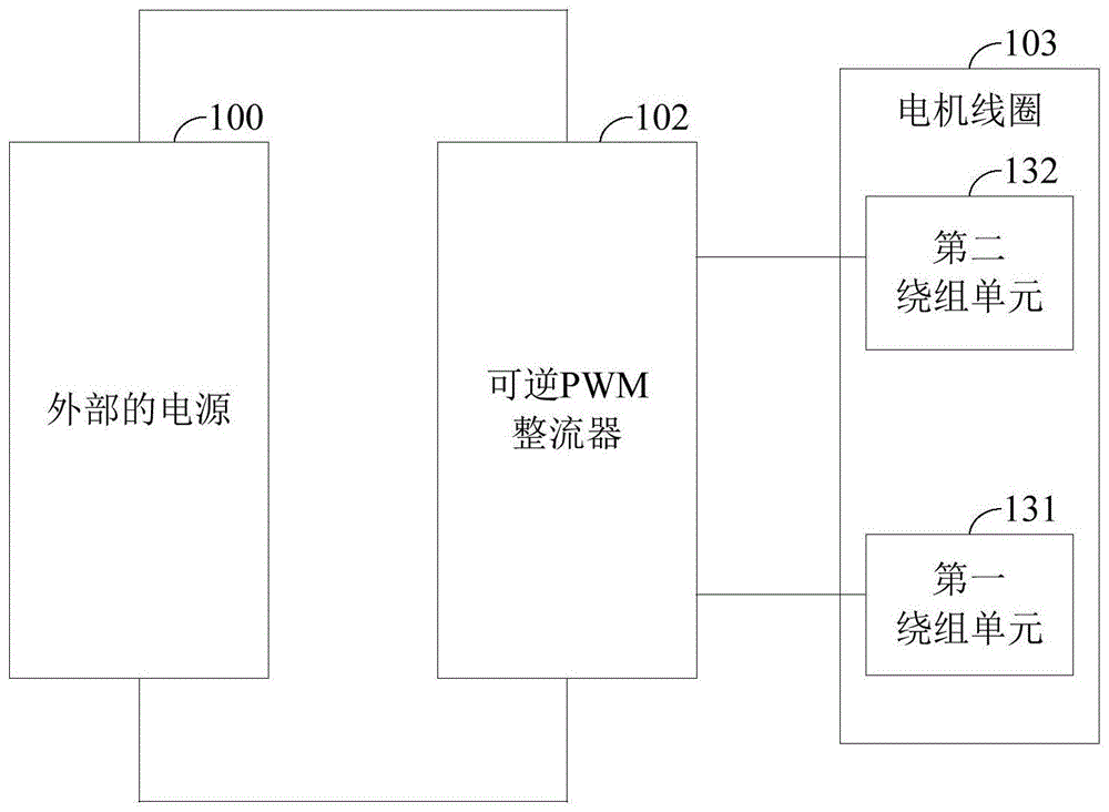
本申请实施例一提供一种能量转换装置,如图1和图2所示,包括可逆PWM整流器102和电机线圈103,电机线圈103包括L套绕组单元,每套绕组与可逆PWM整流器102连接,其中,L≥2,且为正整数;
外部的电源100、可逆PWM整流器102以及电机线圈103中的绕组单元形成至少两套待加热设备的加热电路;The
能量转换装置根据外部信号控制可逆PWM整流器102,使外部的电源100输出的电流流经电机线圈103中的至少两套绕组单元以产生热量,并使至少两套绕组单元在基于电机转子磁场定向的同步旋转坐标系上的交轴电流和直轴电流的合成电流矢量的矢量和为零,其中,第x套绕组单元产生的加热功率为

其中,电机可以是同步电机(含无刷同步机)或者异步电机,电机线圈103的相数大于等于2,电机绕组的套数大于等于2(如双相电机、三相电机、六相电机、九相电机、十五相等等),且电机线圈103的连接点形成中性点引出中性线,电机线圈103的中性线可以是多根数引出,具体电机线圈103的连接点数量取决于电机内部绕组并联结构,电机线圈103在电机内部的并联连接点的数量以及连接点形成中性点引出中性线的数量由实际方案的使用情况确定,其中,电机线圈103包括L套绕组单元,每套绕组与可逆PWM整流器102连接,其中,L≥2;即电机线圈103的部分线圈支路或者全部线圈支路至少构成第一绕组单元和第二绕组单元,第一绕组单元131即第一套绕组单元,第二绕组单元132即第二套绕组单元,第L绕组单元即第L套绕组单元,第一绕组单元131包括至少两个相端点和至少一个中性点,第二绕组单元132包括至少两个相端点和至少一个中性点,第一绕组单元131和第二绕组单元132具有不同的相端点,并且第一绕组单元131和第二绕组单元132均通过相端点连接可逆PWM整流器102,第一绕组单元131的中性点可以引出中性线,也可以处于悬空状态,第二绕组单元132的中性点可以引出中性线,也可以处于悬空状态;同时,每一套绕组单元的所有相绕组作为一个基本单元,对每一个基本单元采用电机矢量控制都可以独立的控制电机运行。可逆PWM整流器102中的PWM为脉冲宽度调制(Pulse width modulation),可逆PWM整流器102包括多相桥臂,桥臂数量根据电机线圈103的相数进行配置,每相逆变器桥臂包括两个功率开关单元,功率开关单元可以是晶体管、IGBT、MOSFET管、SiC管等器件类型,桥臂中两个功率开关单元的连接点连接电机中的一相线圈,可逆PWM整流器102中的功率开关单元可以根据外部控制信号实现导通和关闭。The motor can be a synchronous motor (including a brushless synchronous motor) or an asynchronous motor, the number of phases of the
其中,外部的电源100、可逆PWM整流器102以及电机线圈103中的绕组单元形成至少两套加热电路,外部的电源100、可逆PWM整流器102以及电机线圈103所形成的加热电路是指外部的电源100输出的电流通过可逆PWM整流器102流经电机线圈103时产生热量进而形成加热电路;电机线圈103中的绕组单元至少包括第一绕组单元131和第二绕组单元132,外部的电源100、可逆PWM整流器102、第一绕组单元131形成第一加热电路,外部的电源100输出的电流通过可逆PWM整流器102流经第一绕组单元131时产生热量进而形成第一加热电路;外部的电源100、可逆PWM整流器102、第二绕组单元132形成第二加热电路,外部的电源100输出的电流通过可逆PWM整流器102流经第二绕组单元132时产生热量进而形成第二加热电路;外部的电源100可以为车辆内的电源,例如,外部的电源100可以为动力电池101,外部的电源100也可以通过为通过直流充放电口连接电机线圈的外部供电设备;对于第一加热电路和第二加热电路可以有多种实现方式,例如,如图3所示,外部的电源100为动力电池101时,动力电池101、可逆PWM整流器102、第一绕组单元131形成第一加热电路,动力电池101、可逆PWM整流器102、第二绕组单元132形成第二加热电路,例如,如图4所示,直流充放电口140可以连接可逆PWM整流器102,直流充放电口140、可逆PWM整流器102、第一绕组单元131形成第一加热电路,直流充放电口140、可逆PWM整流器102、第二绕组单元132形成第二加热电路,例如,如图5所示,直流充放电口140还可以连接第一绕组单元131和第二绕组单元132的中性线,直流充放电口140、第一绕组单元131、可逆PWM整流器102形成第一加热电路,直流充放电口140、第二绕组单元132、可逆PWM整流器102形成第二加热电路。The
其中,能量转换装置还包括控制器,控制器与可逆PWM整流器102连接,并向可逆PWM整流器102发送控制信号,控制器可以包括整车控制器、可逆PWM整流器102的控制电路和BMS电池管理器电路,三者通过CAN线连接,控制器中的不同模块根据所获取的信息控制可逆PWM整流器102中功率开关单元的导通和关断以实现不同电流回路的导通;控制器向能量转换装置中的可逆PWM整流器102发送控制信号,使外部的电源100输出的电流流经电机线圈103中的至少两套绕组单元以产生热量,以加热流经电机线圈103的冷却管中的冷却液,当该冷却液流经动力电池101时加热动力电池101。The energy conversion device further includes a controller, which is connected to the
其中,能量转换装置根据外部控制信号使至少两套绕组单元在基于电机转子磁场定向的同步旋转坐标系上的交轴电流和直轴电流的合成电流矢量的矢量和为零,是指每套绕组单元在同步旋转坐标系上交轴电流和直轴电流均形成一个合成电流矢量,即每套绕组单元对应一个电机转子的基于电机转子磁场定向的同步旋转坐标系(直轴-交轴坐标系),此坐标系与转子同步转动,取转子磁场方向为直轴,垂直于转子磁场方向为交轴,将电机的数学模型转换到此坐标系下,可实现直轴和交轴的解耦,从而得到良好控制特性,基于电机转子磁场定向的同步旋转坐标系中的直轴电流id和交轴电流iq合成的矢量为该套绕组单元的合成电流矢量is,合成电流矢量的矢量和为所有套绕组在同步旋转坐标系合成电流矢量的矢量之和,能量转换装置根据外部控制信号控制每套绕组单元的合成电流矢量的大小和方向,使所有绕组单元的合成电流矢量的矢量和为零,此时,能量转换装置中的电机不输出扭矩。Wherein, according to the external control signal, the energy conversion device makes the vector sum of the synthetic current vectors of the quadrature-axis current and the direct-axis current of at least two sets of winding units on the synchronous rotating coordinate system based on the magnetic field orientation of the motor rotor to zero, which means that each set of windings is zero. The quadrature axis current and the direct axis current of the unit form a composite current vector in the synchronous rotating coordinate system, that is, each set of winding units corresponds to a synchronous rotating coordinate system (direct axis-orthogonal axis coordinate system) based on the magnetic field orientation of the motor rotor. , this coordinate system rotates synchronously with the rotor, taking the direction of the rotor magnetic field as the straight axis, and the direction perpendicular to the rotor magnetic field as the quadrature axis, and converting the mathematical model of the motor into this coordinate system can realize the decoupling of the direct axis and the quadrature axis, thereby Good control characteristics are obtained. The vector summed by the direct-axis current id and quadrature-axis current i q in the synchronous rotating coordinate system based on the magnetic field orientation of the motor rotor is the combined current vector is of the set of winding units, and the vector sum of the combined current vector is The vector sum of the synthetic current vectors of all sets of windings in the synchronous rotating coordinate system, the energy conversion device controls the magnitude and direction of the synthetic current vectors of each set of winding units according to the external control signal, so that the vector sum of the synthetic current vectors of all winding units is zero , at this time, the motor in the energy conversion device does not output torque.
本申请实施例一种能量转换装置的技术效果在于:通过采用包括可逆PWM整流器102和电机线圈103的能量转换装置,使该能量转换装置与外部的电源100连接时,外部的电源100、可逆PWM整流器102以及电机线圈103中的绕组单元形成至少两套加热电路;控制可逆PWM整流器102使外部的电源100输出的电流流经电机线圈103中的至少两套绕组单元以产生热量,并使至少两套绕组单元的合成电流矢量和为零,使能量转换装置中的电机不输出扭矩,并使外部的电源100输出的电流流经电机线圈103中的至少两套绕组单元以产生热量,以加热流经电机线圈103的冷却管中的冷却液,当该冷却液流经动力电池101时加热动力电池101,可省去额外的动力电池101加热装置,降低了整个装置的成本,且至少两套绕组单元形成至少两套加热电路,加热的功率大,加热速度快,同时两套绕组单元用于加热可实现较大的加热功率的同时每套绕组的发热功率与仅用一套绕组单元加热的功率小,可延长使用寿命。The technical effect of the energy conversion device in the embodiment of the present application is that: by using the energy conversion device including the
作为一种实施方式,当L套绕组单元中的L1套绕组单元工作于加热电路中时,L1套绕组单元对应L1个合成电流矢量,L1个合成电流矢量的幅值相等,且L1个合成电流矢量中相邻两个合成电流矢量之间的角度为
其中,L套绕组单元中的L1套绕组单元工作于加热电路是指能量转换装置中的可逆PWM整流器102根据控制信号使其中的功率开关单元工作时,使外部的电源100输出的电流通过可逆PWM整流器102流经L1套绕组单元,L1套绕组单元对应一个基于电机转子磁场定向的同步旋转坐标系,L1套绕组单元同时对应L1个合成电流矢量,在基于电机转子磁场定向的同步旋转坐标系中L1个合成电流矢量中相邻两个合成电流矢量之间的角度为
需要说明的是,本实施例中,基于电机转子磁场定向的同步旋转坐标系的电流与直轴的角度均为电角度。It should be noted that, in this embodiment, the current of the synchronous rotating coordinate system based on the magnetic field orientation of the motor rotor and the angle of the straight axis are both electrical angles.
对于每个合成电流矢量与电机转子坐标系中的直轴的角度,作为一种实施方式,L1套绕组单元中每套绕组单元的合成电流矢量相对于电机转子坐标系中的直轴的角度固定。For the angle between each composite current vector and the direct axis in the motor rotor coordinate system, as an embodiment, the angle of the composite current vector of each set of winding units in the L1 sets of winding units relative to the direct axis in the motor rotor coordinate system is fixed .
其中,由于每套绕组单元的合成电流矢量相对于电机转子坐标系中的直轴的角度为固定值,并且相邻两个合成电流矢量之间的角度为
对于每个合成电流矢量与电机转子坐标系中的直轴的角度,作为另一种实施方式,L1套绕组单元中每套绕组单元的合成电流矢量幅值不变,且相对于电机转子坐标系中的直轴的角度为变化值。For the angle between each synthetic current vector and the direct axis in the motor rotor coordinate system, as another implementation, the magnitude of the synthetic current vector of each set of winding units in the L1 sets of winding units is unchanged, and relative to the motor rotor coordinate system The angle of the straight axis in is the change value.
其中,L1套绕组单元中每套绕组单元的合成电流矢量相对于电机转子坐标系中的直轴的角度的变化可以根据预设规则进行变化,可以通过设置角度变化公式使角度在一定范围内进行变化,例如,在0度至360度内变化。Among them, the change of the angle of the composite current vector of each set of winding units in the L1 sets of winding units relative to the angle of the direct axis in the motor rotor coordinate system can be changed according to preset rules, and the angle can be changed within a certain range by setting the angle change formula. Variation, for example, from 0 degrees to 360 degrees.
本实施方式与上述实施方式相比,通过控制每套绕组单元的合成电流矢量幅值不变,且相对于电机转子坐标系中的直轴的角度为变化值,可以实现调节每套绕组单元中每相线圈上的电流为正负变化值,调节每相线圈上散发的热量,同时使可逆PWM整流器102中每相桥臂中上下桥臂功率开关单元的通电流均衡,提升了每相桥臂中功率开关单元的寿命。Compared with the above-mentioned embodiments, the present embodiment can control the magnitude of the synthetic current vector of each set of winding units to remain unchanged, and the angle relative to the direct axis in the motor rotor coordinate system to be a variable value, so that the adjustment of each set of winding units can be realized. The current on each phase coil is a positive and negative change value, which adjusts the heat dissipated on each phase coil, and at the same time balances the currents of the power switch units of the upper and lower bridge arms in the bridge arms of each phase in the
进一步的,L1套绕组单元中第一套绕组单元的合成电流矢量与同步旋转坐标系的直轴正方向的角度为θ1=2πf1t+θ,则第K套绕组单元的合成电流矢量与电机转子坐标系中的直轴正方向的角度为
其中,由于第一套绕组单元与其余套绕组单元之间的角度为固定值,当第一套绕组单元的合成电流矢量与电机转子坐标系中的直轴正方向的角度为变化值时,其余套绕组单元的合成电流矢量与电机转子坐标系中的直轴正方向的角度均为变化值,使每套绕组单元的合成电流矢量按照预设方向旋转起来,每套绕组单元中每相线圈的电流正弦变化且幅值一致,每套绕组单元中每相线圈发热一致,每套绕组单元发热完全均衡,电机绕组及各永磁体温度均匀,可以避免部分低性能磁性材料的电机在电机绕组及各永磁体加热温度不均匀,进而避免导致电机的永磁体容易退磁的问题。此外,通过调节变化频率,利用电池不同频率下的阻抗不同,阻抗越大发热越大,增大电池的发热。根据电池不同温度下的加热功率需求,选择合适的幅值和电角度变化频率,便于系统调节和响应。Among them, since the angle between the first set of winding units and the other sets of winding units is a fixed value, when the angle between the composite current vector of the first set of winding units and the positive direction of the direct axis in the motor rotor coordinate system is a changing value, the rest The angle between the composite current vector of the set of winding units and the positive direction of the direct axis in the motor rotor coordinate system is a change value, so that the composite current vector of each set of winding units rotates according to the preset direction. The current changes sinusoidally and has the same amplitude, the coils of each phase in each set of winding units have the same heating, the heating of each set of winding units is completely balanced, and the temperature of the motor winding and each permanent magnet is uniform, which can avoid some motors with low-performance magnetic materials. The heating temperature of the permanent magnets is uneven, thereby avoiding the problem of easy demagnetization of the permanent magnets of the motor. In addition, by adjusting the frequency of change, the impedance of the battery at different frequencies is different, the greater the impedance, the greater the heat, and the heat of the battery is increased. According to the heating power requirements at different temperatures of the battery, select the appropriate amplitude and frequency of electrical angle change, which is convenient for system adjustment and response.
对于合成电流矢量的幅值,作为一种实施方式,L1个合成电流矢量相对于同步旋转坐标系的直轴的角度为固定值,L1个合成电流矢量的幅值相等。As for the amplitudes of the combined current vectors, as an embodiment, the angles of the L1 combined current vectors relative to the straight axis of the synchronous rotating coordinate system are fixed values, and the amplitudes of the L1 combined current vectors are equal.
该角度为电角度,通过设置每个合成电流矢量的幅值相等,可以实现L1个合成电流矢量的幅值在直轴和交轴上的分量相互抵消。The angle is an electrical angle. By setting the amplitudes of each composite current vector to be equal, the components of the amplitudes of the L1 composite current vectors on the direct axis and the quadrature axis can cancel each other out.
对于合成电流矢量的幅值,作为另一种实施方式,L1个合成电流矢量相对于同步旋转坐标系的直轴的角度为固定值,L1个合成电流矢量的幅值相等且为变化值,L1个合成电流矢量的幅值为

本实施方式与上一实施方式相比,通过调节合成电流矢量的幅值为正弦变化,可以使PWM整流器中上下桥臂功率器件(含二极管)通电流均衡,使功率器件寿命均衡,合成电流矢量的幅值的每相绕组电流虽然不完全一样,但是每相电流正弦变化的信号可以使每套绕组的每相绕组受热更均衡,并且通过调整合成电流矢量幅值的变化频率f2,利用电池在不同频率下的阻抗不同,阻抗越大发热越大,可以增大电池的发热。Compared with the previous embodiment, by adjusting the amplitude of the combined current vector to a sinusoidal change, the current in the upper and lower arm power devices (including diodes) in the PWM rectifier can be balanced, so that the life of the power devices can be balanced, and the combined current vector can be balanced. Although the winding currents of each phase of the amplitude are not exactly the same, the sinusoidal change signal of each phase current can make the heating of each phase winding of each set of windings more balanced, and by adjusting the change frequency f 2 of the amplitude of the synthetic current vector, the battery can be used The impedance at different frequencies is different. The larger the impedance, the greater the heat generation, which can increase the heat generation of the battery.
作为一种实施方式,当L套绕组单元中的L2套绕组单元工作于加热电路中时,L2套绕组单元对应L2个合成电流矢量,并形成
其中,由于每一对合成电流矢量中的两个合成电流矢量之间的电角度相差180°,可以使合成电流矢量的幅值大小相等方向相反,即每一对合成电流矢量的矢量和为0,进而
对于每个合成电流矢量与电机转子坐标系中的直轴的角度,作为一种实施方式,L2套绕组单元中每套绕组单元的合成电流矢量相对于电机转子坐标系中的直轴的角度固定或L2套绕组单元中至少一对绕组单元的合成电流矢量相对于电机转子坐标系中的直轴的角度固定。For the angle between each composite current vector and the direct axis in the motor rotor coordinate system, as an implementation manner, the angle of the composite current vector of each set of winding units in the L2 sets of winding units relative to the direct axis in the motor rotor coordinate system is fixed Or the angle of the resultant current vector of at least one pair of winding units in the L2 set of winding units is fixed with respect to the direct axis in the motor rotor coordinate system.
其中,由于每套绕组单元的合成电流矢量相对于电机转子坐标系中的直轴的角度为固定值,并且
对于每个合成电流矢量与电机转子坐标系中的直轴的角度,作为一种实施方式,L2套绕组单元中至少一对绕组单元的合成电流矢量相对于同步旋转坐标系的直轴的角度为变化值,一对合成电流矢量中一个合成电流矢量相对于同步旋转坐标系中的直轴的角度为θL/2-1=2πf1t+θL/2,另一个合成电流矢量相对于电机转子坐标系中的直轴的角度为θL/2-2=2πf1t+180+θL/2,其中,f1为合成电流矢量相对于同步旋转坐标系的直轴的角度的变化频率,θL/2为该对合成电流矢量中的一个合成电流矢量相对于电机转子坐标系中的直轴的角度的初始角度。For the angle between each composite current vector and the direct axis in the motor rotor coordinate system, as an implementation manner, the angle of the composite current vector of at least one pair of winding units in the L2 set of winding units relative to the direct axis of the synchronous rotation coordinate system is: Variation value, the angle of one synthetic current vector in a pair of synthetic current vectors relative to the straight axis in the synchronous rotating coordinate system is θ L/2-1 = 2πf 1 t+θ L/2 , and the other synthetic current vector is relative to the motor The angle of the straight axis in the rotor coordinate system is θ L/2-2 =2πf 1 t+180+θ L/2 , where f 1 is the frequency of change of the angle of the resultant current vector relative to the straight axis of the synchronous rotating coordinate system , θ L/2 is the initial angle of one of the pair of resultant current vectors relative to the angle of the straight axis in the motor rotor coordinate system.
其中,由于一对合成电流矢量中两个合成电流矢量值相差180度,当其中一个合成电流矢量与电机转子坐标系中的直轴正方向的角度为变化值时,该对合成电流矢量中另一个合成电流矢量与电机转子坐标系中的直轴正方向的角度均为变化值,使每对绕组单元的合成电流矢量按照预设方向旋转起来,每对绕组单元中每相线圈的电流正弦变化且幅值一致,每套绕组单元中每相线圈发热一致,每套绕组单元发热完全均衡,电机绕组及各永磁体温度均匀,可以避免部分低性能磁性材料的电机在电机绕组及各永磁体加热温度不均匀,进而避免导致电机的永磁体容易退磁的问题。Among them, since the two composite current vector values in a pair of composite current vectors differ by 180 degrees, when the angle between one composite current vector and the positive direction of the straight axis in the motor rotor coordinate system is a change value, the other value of the composite current vector in the pair of composite current vectors is a change value. The angle between a composite current vector and the positive direction of the direct axis in the motor rotor coordinate system is a change value, so that the composite current vector of each pair of winding units rotates according to the preset direction, and the current of each phase coil in each pair of winding units changes sinusoidally And the amplitude is the same, the heating of each phase coil in each winding unit is the same, the heating of each winding unit is completely balanced, and the temperature of the motor winding and each permanent magnet is uniform, which can avoid some motors with low-performance magnetic materials. The temperature is not uniform, thereby avoiding the problem that the permanent magnets of the motor are easily demagnetized.
作为一种实施方式,至少一对合成电流矢量的幅值相等且为变化值,该对合成电流矢量相对于同步旋转坐标系的直轴的电角度为固定值;As an embodiment, the amplitudes of at least one pair of synthesized current vectors are equal and change values, and the electrical angle of the pair of synthesized current vectors relative to the direct axis of the synchronous rotating coordinate system is a fixed value;
至少一对合成电流矢量的幅值为

本实施方式通过调节合成电流矢量的幅值相等且为正弦变化,可以使PWM整流器中上下桥臂功率器件(含二极管)通电流均衡,使功率器件寿命均衡,合成电流矢量的幅值的每相绕组电流虽然不完全一样,但是每相电流正弦变化的信号可以使每套绕组的每相绕组受热更均衡,并且通过调整合成电流矢量幅值的变化频率f2,利用电池在不同频率下的阻抗不同,阻抗越大发热越大,可以增大电池的发热。In this embodiment, by adjusting the amplitudes of the synthesized current vectors to be equal and sinusoidal, the currents of the upper and lower arm power devices (including diodes) in the PWM rectifier can be balanced, and the life of the power devices can be balanced. Although the winding currents are not exactly the same, the sinusoidal variation of each phase current can make the heating of each phase winding of each set of windings more balanced, and by adjusting the change frequency f 2 of the magnitude of the synthetic current vector, the impedance of the battery at different frequencies can be used. Different, the greater the impedance, the greater the heat generation, which can increase the heat generation of the battery.
作为一种实施方式,本实施方式用于通过控制器实现外部的电源100向能量转换装置输出电流使电机线圈103进行加热,能量转换装置包括控制器,控制器连接可逆PWM整流器102,控制器用于:As an embodiment, this embodiment is used to realize that the
获取电机线圈103需要产生的目标加热功率,控制器可以接收整车控制器输出的控制信号获取目标加热功率;To obtain the target heating power that the
根据目标加热功率获得每套绕组单元的目标合成电流矢量;Obtain the target synthetic current vector of each set of winding units according to the target heating power;
根据目标合成电流矢量获取每套绕组单元分别在同步旋转坐标系上的直轴和交轴上的目标直轴电流和目标交轴电流;Obtain the target direct axis current and the target quadrature axis current on the direct axis and quadrature axis of each set of winding units respectively on the synchronous rotation coordinate system according to the target composite current vector;
根据每套绕组单元的采样电流值获取每套绕组单元分别在同步旋转坐标系上的直轴和交轴上的实际直轴电流和实际交轴电流,并根据目标交轴电流、目标直轴电流、实际交轴电流、实际直轴电流获取每套绕组单元连接的可逆PWM整流器102的每相桥臂的占空比。According to the sampled current value of each set of winding units, the actual direct-axis current and actual quadrature-axis current on the direct-axis and quadrature-axis of each set of winding units on the synchronous rotating coordinate system are obtained, and the target quadrature-axis current and target direct-axis current , the actual quadrature axis current, and the actual direct axis current to obtain the duty ratio of each phase bridge arm of the
其中,根据目标加热功率获得每套绕组单元的目标合成电流矢量,包括:Among them, the target synthetic current vector of each set of winding units is obtained according to the target heating power, including:
根据以下公式获得每套绕组单元的目标合成电流矢量:The target resultant current vector for each set of winding elements is obtained according to the following formula:

其中,P为目标加热功率,Rs为工作于加热电路的第n套绕组单元各相绕组的相电阻,
根据目标加热功率和上述公式获得每套绕组单元的目标合成电流矢量的幅值,根据每套绕组单元的目标合成电流矢量的幅值和电角度获取每套绕组单元分别在同步旋转坐标系上的直轴和交轴上的目标直轴电流和目标交轴电流,再根据每套绕组单元的采样电流值和转子电角度获取每套绕组单元的实际交轴电流和实际直轴电流;再将每套绕组单元的实际交轴电流和目标交轴电流进行闭环控制后得到第一目标电压差值,以及将每套绕组单元的实际直轴电流和目标直轴电流进行闭环控制后得到第二目标电压差值,再将第一目标电压差值和第二目标电压差值通过反Park变换并传输至空间矢量脉宽调制算法(SVPWM)得到可逆PWM整流器102的m相桥臂占空比。According to the target heating power and the above formula, the amplitude of the target composite current vector of each set of winding units is obtained. The target direct-axis current and the target quadrature-axis current on the direct-axis and quadrature-axis, and then obtain the actual quadrature-axis current and actual direct-axis current of each set of winding units according to the sampled current value and rotor electrical angle of each set of winding units; The first target voltage difference is obtained after the closed-loop control of the actual quadrature-axis current and the target quadrature-axis current of the set of winding units, and the second target voltage is obtained after closed-loop control of the actual direct-axis current and target direct-axis current of each set of winding units Then, the first target voltage difference and the second target voltage difference are inversely Park transformed and transmitted to the space vector pulse width modulation algorithm (SVPWM) to obtain the duty ratio of the m-phase bridge arm of the
本实施方式中通过控制器向可逆PWM整流器102输出m相桥臂占空比,即可以实现控制外部电源向电机线圈103的绕组单元输出电流流经电机线圈103中的至少两套绕组单元以输出目标加热功率。In this embodiment, the controller outputs the duty ratio of the m-phase bridge arm to the
作为一种实施方式,本实施方式为外部电源为动力电池101时,并且动力电池101向能量转换装置输出电流使电机线圈103输出目标加热功率。As an embodiment, this embodiment is when the external power source is the
其中,动力电池101、可逆PWM整流器102以及电机线圈103中的绕组单元形成至少两套加热电路。The
对于可逆PWM整流器102,如图6所示,可逆PWM整流器102包括一组M1路桥臂,M1路桥臂形成第一汇流端和第二汇流端,动力电池101的正极端和负极端分别连接第一汇流端和第二汇流端,电机线圈103包括第一绕组单元131和第二绕组单元132;For the
第一绕组单元131包括一套m1相绕组,m1相绕组中的每一相绕组包括n1个线圈支路,每一相绕组的n1个线圈支路共接形成一个相端点,m1相绕组的相端点与M1路桥臂中的m1路桥臂的每路桥臂的中点一一对应连接,m1相绕组中的每一相绕组的n1个线圈支路中的一个线圈支路还分别与其他相绕组中的n1个线圈支路中的一个线圈支路连接,以形成n1个连接点,其中,m1≥2,n1≥1且n1,m1均为整数;The first winding
第二绕组单元132包括一套m2相绕组,m2相绕组中的每一相绕组包括n2个线圈支路,每一相绕组的n2个线圈支路共接形成一个相端点,m2相绕组的相端点与M1路桥臂中m2路桥臂的每路桥臂的中点一一对应连接,m2相绕组中的每一相绕组的n2个线圈支路中的一个线圈支路还分别与其他相绕组中的n2个线圈支路中的一个线圈支路连接,以形成n2个连接点,其中,m2≥2,M1≥m1+m2,n2≥1且n2,m2,M1均为整数;The second winding
动力电池101、可逆PWM整流器102以及第一绕组单元131形成第一加热电路,动力电池101、可逆PWM整流器102以及第二绕组单元132形成第二加热电路。The
本实施方式中,根据外部控制信号控制可逆PWM整流器102,使动力电池101输出的电流流经第一绕组单元131和第二绕组单元132以产生热量,并使第一绕组单元131和第二绕组单元132的合成电流矢量和为零,以使能量转换装置产生热量并不输出扭矩。In this embodiment, the
作为另一种实施方式,外部的直流充放电口、可逆PWM整流器102以及电机线圈103中的绕组单元形成至少两套加热电路,其中,外部的直流充放电口连接电机线圈103引出的至少一条中性线;As another embodiment, the external DC charging and discharging port, the
外部的电源100为直流供电设备,直流供电设备连接外部的直流充放电口;The
可逆PWM整流器102包括一组M1路桥臂,电机线圈103包括第一绕组单元131和第二绕组单元132;The
第一绕组单元131包括一套m1相绕组,m1相绕组中的每一相绕组包括n1个线圈支路,每一相绕组的n1个线圈支路共接形成一个相端点,m1相绕组的相端点与M1路桥臂中的m1路桥臂的每路桥臂的中点一一对应连接,m1相绕组中的每一相绕组的n1个线圈支路中的一个线圈支路还分别与其他相绕组中的n1个线圈支路中的一个线圈支路连接,以形成n1个连接点,n1个连接点形成T1个中性点,从T1个中性点引出J1条中性线;其中,n1≥T1≥1,T1≥J1≥1,m1≥2且n1,m1,T1,J1均为正整数;The first winding
第二绕组单元132包括一套m2相绕组,m2相绕组中的每一相绕组包括n2个线圈支路,每一相绕组的n2个线圈支路共接形成一个相端点,m2相绕组的相端点与M1路桥臂中m2路桥臂的每路桥臂的中点一一对应连接,m2相绕组中的每一相绕组的n2个线圈支路中的一个线圈支路还分别与其他相绕组中的n2个线圈支路中的一个线圈支路连接,以形成n2个连接点,n2个连接点形成T2个中性点,从T2个中性点引出J2条中性线;其中,n2≥T2≥1,T2≥J2≥1,m2≥2,M≥m1+m2且n2,m2,T2,J2均为正整数;The second winding
直流供电设备、第一绕组单元131以及可逆PWM整流器102形成第三加热电路,直流供电设备、第二绕组单元132以及可逆PWM整流器102形成第四加热电路。The DC power supply device, the first winding
本实施方式中,根据外部控制信号控制可逆PWM整流器102,使直流供电设备输出的电流流经第一绕组单元131和第二绕组单元132以产生热量,并使第一绕组单元131和第二绕组单元132的合成电流矢量和为零,以使能量转换装置产生热量并不输出扭矩,且待加热的电池电量不足时,可通过外部的直流充放电口连接的直流供电设备供电。In this embodiment, the
作为另一种实施方式,本实施方式用于实现动力电池101向能量转换装置输出电流使电机线圈103产生热量,同时直流供电设备通过能量转换装置对动力电池101进行充电,以及实现动力电池101向能量转换装置输出电流使电机线圈103产生热量,同时动力电池101通过能量转换装置对直流用电设备进行放电。As another implementation, this implementation is used to realize that the
外部的电源100为动力电池101和直流供电设备,动力电池101连接可逆PWM整流器102,外部的直流充放电口140连接电机线圈103引出的至少一条中性线,直流供电设备连接外部的直流充放电口140;The
动力电池101、可逆PWM整流器102以及电机线圈103中的绕组单元形成至少两套加热电路,直流供电设备、电机线圈103、可逆PWM整流器102、动力电池101形成直流充电电路;The
或者,外部的电源100为动力电池101,动力电池101连接可逆PWM整流器102,外部的直流充放电口140连接电机线圈103引出的至少一条中性线,外部的直流充放电口140连接直流供电设备;Alternatively, the
动力电池101、可逆PWM整流器102以及电机线圈103中的绕组单元形成至少两套加热电路,动力电池101、可逆PWM整流器102、电机线圈103、直流用电设备形成直流放电电路;The
控制器还用于:Controllers are also used to:
获取电机线圈103需要产生的目标加热功率和动力电池101的目标充电功率或者目标放电功率;Obtain the target heating power to be generated by the
根据目标充电功率或者目标放电功率获取每套绕组单元的目标充电电流或者目标放电电流,根据目标充电电流或者目标放电电流获取每套绕组单元产生的第一加热功率;Obtain the target charging current or target discharging current of each set of winding units according to the target charging power or target discharging power, and obtain the first heating power generated by each set of winding units according to the target charging current or target discharging current;
根据目标加热功率和每套绕组单元产生的第一加热功率获取每套绕组单元产生的第二加热功率;Obtain the second heating power generated by each set of winding units according to the target heating power and the first heating power generated by each set of winding units;
根据第二加热功率获得每套绕组单元的目标合成电流矢量,根据目标合成电流矢量获取每套绕组单元分别在同步旋转坐标系上的直轴和交轴上的目标直轴电流和目标交轴电流;The target combined current vector of each set of winding units is obtained according to the second heating power, and the target direct-axis current and the target quadrature-axis current on the direct axis and quadrature axis of each set of winding units respectively on the synchronous rotating coordinate system are obtained according to the target combined current vector ;
根据每套绕组单元的采样电流值获取每套绕组单元分别在所述同步旋转坐标系上的直轴和交轴上的实际直轴电流、实际交轴电流和零轴电流,并根据目标交轴电流、目标直轴电流、实际交轴电流、实际直轴电流进行闭环控制获取每套绕组单元连接的可逆PWM整流器的每相桥臂的第一占空比(D11、D12…D1m);According to the sampled current value of each set of winding units, the actual direct-axis current, actual quadrature-axis current and zero-axis current on the direct-axis and quadrature-axis of each set of winding units on the synchronous rotating coordinate system are obtained, and according to the target quadrature axis Close-loop control is performed on the current, target direct-axis current, actual quadrature-axis current, and actual direct-axis current to obtain the first duty cycle of each phase bridge arm of the reversible PWM rectifier connected to each set of winding units (
根据目标充电电流或者目标放电电流和零轴电流进行闭环控制获取每套绕组单元连接的可逆PWM整流器的桥臂的的占空比调节值(D0);Perform closed-loop control according to the target charging current or target discharging current and the zero-axis current to obtain the duty cycle adjustment value (D0) of the bridge arm of the reversible PWM rectifier connected to each set of winding units;
根据所述第一占空比和所述占空比调节值获取每套绕组单元连接的所述可逆PWM整流器的每相桥臂的占空比(D1、D2…Dm)。The duty ratio (D1, D2...Dm) of each phase bridge arm of the reversible PWM rectifier connected to each set of winding units is obtained according to the first duty cycle and the duty cycle adjustment value.
其中,第x套绕组单元产生的第一加热功率为


其中,根据目标充电功率获取每套绕组单元的目标充电电流,可以使每套绕组单元中流过的电流相同,根据目标充电电流获取每套绕组单元产生的第一加热功率,由于第一加热功率和第二加热功率的和为目标加热功率,因此,通过目标加热功率减去每套绕组单元产生的第一加热功率获取每套绕组单元产生的第二加热功率;Among them, obtaining the target charging current of each set of winding units according to the target charging power can make the current flowing in each set of winding units the same, and obtaining the first heating power generated by each set of winding units according to the target charging current, because the first heating power and The sum of the second heating power is the target heating power, therefore, the second heating power generated by each set of winding units is obtained by subtracting the first heating power generated by each set of winding units from the target heating power;
根据第二加热功率获得每套绕组单元的目标合成电流矢量,包括:Obtain the target composite current vector of each set of winding units according to the second heating power, including:
根据以下公式获得每套绕组单元的目标合成电流矢量:The target resultant current vector for each set of winding elements is obtained according to the following formula:

其中,P为目标加热功率,Rs工作于加热电路的第n套绕组单元各相绕组的相电阻,isn为第n套绕组单元的电流在直轴和交轴的合成电流矢量,m为可逆PWM整流器102中的桥臂的相数。Among them, P is the target heating power, R s works on the phase resistance of each phase winding of the nth set of winding units of the heating circuit, isn is the composite current vector of the current of the nth set of winding units on the direct axis and the quadrature axis, m is The number of phases of the bridge arms in the
根据第二加热功率和上述公式获得每套绕组单元的目标合成电流矢量的幅值,根据每套绕组单元的目标合成电流矢量的幅值和电角度获取每套绕组单元分别在同步旋转坐标系上的直轴和交轴上的目标直轴电流和目标交轴电流,再根据每套绕组单元的采样电流值和转子电角度获取每套绕组单元的实际交轴电流和实际直轴电流;再将每套套组单元的实际交轴电流和目标交轴电流进行差值运算后再经过PID(比例积分微分)运算后得到第一目标电压差值,以及将每套绕组单元的实际直轴电流和目标直轴电流进行差值运算后再经过PID(比例积分微分)运算后得到第二目标电压差值,再将第一目标电压差值和第二目标电压差值通过反Park变换并传输至空间矢量脉宽调制算法(SVPWM)得到可逆PWM整流器102的m相桥臂的第一占空比,根据目标合成电流矢量和电机相数计算每套绕组单元的目标电流值,将每套绕组单元的目标充电电流或者目标放电电流与
本实施方式中通过控制器向可逆PWM整流器102输出总的占空比,即可以实现控制动力电池向电机线圈103的绕组单元输出电流流经电机线圈103中的至少两套绕组单元以输出目标加热功率,同时实现直流供电设备通过能量转换装置向动力电池进行充电。In this embodiment, the controller outputs the total duty cycle to the
本实施方式的技术效果在于:通过在能量转换装置中设置电机线圈103、可逆PWM整流器102并与动力电池101及直流供电设备形成直流充电电路,仅需要控制可逆PWM整流器102的工作状态进而调节直流供电设备和动力电池101流向充电电路的电流,即可实现使对动力电池101进行充电的同时使电机线圈103进行加热,进而实现采用同一系统对电池进行充电和使电机线圈103进行耗电产生热量,元器件复用程度高,系统集成度高且结构简单,从而降低了系统成本,减小了系统体积。The technical effect of this embodiment is that: by arranging the
作为一种实施方式,电机线圈103包括第一绕组单元131和第二绕组单元132,动力电池101、可逆PWM整流器102以及第一绕组单元131形成第一加热电路,动力电池101、可逆PWM整流器102以及第二绕组单元132形成第二加热电路,外部的直流充放电口通过能量转换装置与外部的电池形成直流充电电路或者直流放电电路,其中,可逆PWM整流器102还包括第一汇流端和第二汇流端,外部的直流充放电口的第一端连接电机线圈103引出的至少一条中性线,外部的直流充放电口的第二端连接第二汇流端,外部的电池的正极端连接第一汇流端,外部的电池的负极端连接第二汇流端,外部的直流充放电口连接直流供电设备。As an embodiment, the
本实施方式中,直流供电设备、第一绕组单元131、可逆PWM整流器102、动力电池101形成第一直流充电电路,直流供电设备、第二绕组单元132、可逆PWM整流器102、动力电池101形成第二直流充电电路,能量转换装置根据外部控制信号使第一直流充电电路、第一加热电路以及第二加热电路同时工作或者使第二直流充电电路、第一加热电路以及第二加热电路同时工作。In this embodiment, the DC power supply device, the first winding
作为一种连接方式,外部的第一直流充放电口通过能量转换装置与外部的电池形成第一直流充电电路或者第一直流放电电路,外部的第二直流充放电口通过能量转换装置与外部的电池形成第二直流充电电路或者第二直流放电电路,其中,可逆PWM整流器102还包括第一汇流端和第二汇流端,外部的第一直流充放电口的第一端连接电机线圈103的第一绕组单元131的第一中性线,外部的第二直流充放电口的第一端连接电机线圈103的第二绕组单元132的第二中性线,外部的第一直流充放电口的第二端和外部的第二直流充放电口的第二端连接第二汇流端,外部的电池的正极端连接第一汇流端,外部的电池的负极端连接第二汇流端。As a connection method, the external first DC charging and discharging port forms a first DC charging circuit or a first DC discharging circuit with the external battery through the energy conversion device, and the external second DC charging and discharging port passes through the energy conversion device. A second DC charging circuit or a second DC discharging circuit is formed with an external battery, wherein the
图7为本实施方式提供的能量转换装置的电路图,以m1=m2=3,M1=6,n1=n2=2为例,能量转换装置包括可逆PWM整流器102、电机线圈103,还包括第一开关模块106,第一开关模块106包括开关K3、开关K4,电阻R、开关K5以及电容C1,外部的电池的正极连接开关K3的第一端和开关K4的第一端,开关K4的第二端连接电阻R的第一端,开关K3的第二端和电阻R的第二端连接电容C1的第一端,电池的负极连接开关K5的第一端,开关K5的第二端连接电容C1的第二端,可逆PWM整流器102包括六相桥臂,第一相桥臂包括串联连接的第一功率开关单元和第二功率开关单元,第二相桥臂包括串联连接的第三功率开关单元和第四功率开关单元,第三相桥臂包括串联连接的第五功率开关单元和第六功率开关单元,第四相桥臂包括串联连接的第七功率开关单元和第八功率开关单元,第五相桥臂包括串联连接的第九功率开关单元和第十功率开关单元,第六相桥臂包括串联连接的第十一功率开关单元和第十二功率开关单元,第一功率开关单元的输入端、第三功率开关单元的输入端、第五功率开关单元的输入端、第七功率开关单元的输入端、第九功率开关单元的输入端、第十一功率开关单元的输入端共接于电容C1的第一端并形成第一汇流端,第二功率开关单元的输出端、第四功率开关单元的输出端、第六功率开关单元的输出端、第八功率开关单元的输出端、第十功率开关单元、第十二功率开关单元的输出端共接于电容C1的第二端并形成第二汇流端,第一功率开关单元包括第一上桥臂VT1和第一上桥二极管VD1,第二功率开关单元包括第二下桥臂VT2和第二下桥二极管VD2,第三功率开关单元包括第三上桥臂VT3和第三上桥二极管VD3,第四功率开关单元包括第四下桥臂VT4和第四下桥二极管VD4,第五功率开关单元包括第五上桥臂VT5和第五上桥二极管VD5,第六功率开关单元包括第六下桥臂VT6和第六下桥二极管VD6,第七功率开关单元包括第七上桥臂VT7和第七上桥二极管VD7,第八功率开关单元包括第八下桥臂VT8和第八下桥二极管VD8,第九功率开关单元包括第九上桥臂VT9和第九上桥二极管VD9,第十功率开关单元包括第十下桥臂VT10和第十下桥二极管VD10,第十一功率开关单元包括第十一上桥臂VT11和第十一上桥二极管VD11,第十二功率开关单元包括第十二下桥臂VT12和第十二下桥二极管VD12,第一绕组单元131包括一套三相绕组,每相绕组包括两个线圈支路,第一相线圈中的线圈U1、线圈U2共接于第四相桥臂的中点U,第二相线圈中线圈V1、线圈V2共接于第五相桥臂的中点V,第三相线圈中线圈W1、线圈W2共接于第六相桥臂的中点W,线圈U2、线圈V2、线圈W2共接形成第一连接点n1,第一连接点n1形成第一独立中性点,第一独立中性点引出第一中性线,线圈U1、线圈V1、线圈W1共接形成第二连接点n2,第二连接点n2形成第二独立中性点,第二绕组单元132包括一套三相绕组,每相绕组包括两个线圈支路,第一相线圈中的线圈A1、线圈A2共接于第一相桥臂的中点A,第二相线圈中线圈B1、线圈B2共接于第二相桥臂的中点B,第三相线圈中线圈C1、线圈C2共接于第三相桥臂的中点C,线圈A1、线圈B1、线圈C1共接形成第四连接点n4,线圈A2、线圈B2、线圈C2共接形成第三连接点n3,第三连接点n3形成第三独立中性点,第三独立中性点引出第二中性线,能量转换模块还包括开关K1、开关K2、第二开关模块107和第三开关模块108,第二开关模块107包括开关K6、开关K7、电容C2,第三开关模块108包括开关K10、开关K11以及电容C3,外部的第一直流充放电口104的第一端和第二端分别连接开关K6的第二端和开关K7的第二端,开关K6的第一端连接开关K1的第二端和电容C2的第一端,开关K1的第一端连接第一中性线,开关K7的第一端连接电容C2的第二端和可逆PWM整流器102的第二汇流端,第二中性线连接开关K2的第一端,开关K2的第二端连接电容C3的第一端和开关K10的第一端,开关K10的第二端连接第二直流充放电口105的第一端,电容C3的第二端连接开关K11的第一端和第二汇流端,开关K11的第二端连接第二直流充放电口105的第二端。FIG. 7 is a circuit diagram of an energy conversion device provided in this embodiment. Taking m 1 =m 2 =3, M 1 =6, and n 1 =n 2 =2 as an example, the energy conversion device includes a
本实施方式中,通过设置第一直流充放电口104和第二直流充放电口105分别与第一中性线和第二中性线连接,可以使第一直流充放电口104、第一绕组单元131、可逆PWM整流器102形成加热电路,使第二直流充放电口105、第二绕组单元132、可逆PWM整流器102形成加热电路,还可以实现第一直流充放电口104与第二直流充放电口105通过能量转换装置与动力电池101形成充放电回路。In this embodiment, by setting the first DC charging and discharging
如图8所示,与图7的不同点在于还包括开关K8和开关K9,第三连接点n3形成中性点并引出第一中性线,第一中性线连接开关K1的第一端,外部的第一直流充放电口104的第一端和第二端分别连接开关K6的第二端和开关K7的第二端,开关K6的第一端连接开关K1的第二端和电容C2的第一端,开关K1的第一端连接第一中性线,开关K7的第二端连接电容C2的第二端和可逆PWM整流器102的第二汇流端,外部的第三直流充放电口110的第一端连接开关K8的第一端,开关K8的第二端连接开关K3的第二端,外部的第三直流充放电口110的第二端连接开关K9的第一端,开关K9的第二端连接开关K5的第二端。As shown in FIG. 8, the difference from FIG. 7 is that it also includes a switch K8 and a switch K9, the third connection point n3 forms a neutral point and leads out a first neutral line, and the first neutral line is connected to the first end of the switch K1 , the first terminal and the second terminal of the external first DC charging/discharging
本实施方式中,通过设置第三直流充放电口110与可逆PWM整流器102连接,不仅可以实现动力电池101、可逆PWM整流器102以及电机线圈103中的绕组单元形成两套加热电路,还可以实现第三直流充放电口110、可逆PWM整流器102以及电机线圈103中的绕组单元形成两套加热电路。In this embodiment, by setting the third DC charging/discharging
如图9所示,与图7的不同点在于第一绕组单元131和第二绕组单元132中的线圈支路n1=n2=1,第一绕组单元131形成第一连接点n1,第二绕组单元132形成第二连接点n2,第一连接点n1和第二连接点n2共接形成第一中性点,第一中性点引出第一中性线,第一中性线连接开关K1的第一端,外部的第一直流充放电口104的第一端和第二端分别连接开关K6的第二端和开关K7的第二端,开关K6的第一端连接开关K1的第二端和电容C2的第一端,开关K1的第一端连接第一中性线,开关K7的第二端连接电容C2的第二端和可逆PWM整流器102的第二汇流端。As shown in FIG. 9 , the difference from FIG. 7 is that the coil branches in the first winding
本实施方式中,通过设置一个第一直流充放电口104与第一中性线连接,实现了仅需要设置一个第一直流充放电口104,即可以实现第一直流充放电口、电机线圈103中的绕组单元以及可逆PWM整流器102形成两套加热电路,并且该第一直流充放电口通过能量转换装置与动力电池101形成充放电回路。In this embodiment, by setting one first DC charging and discharging
如图10所示,与图7的不同点在于还包括开关K8和开关K9,外部的第三直流充放电口110的第一端连接开关K8的第一端,开关K8的第二端连接开关K3的第二端,外部的第三直流充放电口110的第二端连接开关K9的第一端,开关K9的第二端连接开关K5的第二端。As shown in FIG. 10 , the difference from FIG. 7 is that it also includes a switch K8 and a switch K9 , the first end of the external third DC charging and discharging
本实施方式中,通过设置第一直流充放电口104、第二直流充放电口105、第三直流充放电口110,可以实现第一直流充放电口104、第一绕组单元131、可逆PWM整流器102形成一套加热电路,第二直流充放电口105、第二绕组单元132、可逆PWM整流器102形成一套加热电路,第三直流充放电口110、可逆PWM整流器102、第一绕组单元131形成一套加热电路,第三直流充放电口110、可逆PWM整流器102、第二绕组单元132形成一套加热电路,还可以实现第一直流充放电口104、第二直流充放电口105分别通过能量转换装置与动力电池101形成充放电回路。In this embodiment, by setting the first DC charging and discharging
下面针对具体电路结构对本申请的具体工作原理进行说明:The specific working principle of the present application is described below with respect to the specific circuit structure:
当能量转换装置仅用于加热时,充电电流等于0,扭矩等于0,获取目标加热功率P,根据以下公式计算每套绕组单元的目标合成电流矢量:When the energy conversion device is only used for heating, the charging current is equal to 0, the torque is equal to 0, the target heating power P is obtained, and the target combined current vector of each set of winding units is calculated according to the following formula:

其中,P为目标加热功率,Rs为工作于加热电路的第n套绕组单元各相绕组的相电阻,isn为第n套绕组单元的电流在直轴和交轴的合成电流矢量,m为可逆PWM整流器102中的桥臂的相数Among them, P is the target heating power, R s is the phase resistance of each phase winding of the nth set of winding units working in the heating circuit, isn is the combined current vector of the current of the nth set of winding units on the direct axis and the quadrature axis, m is the phase number of the bridge arm in the
方法A:电机的绕组单元n为电机绕组的套数,根据式1,由加热功率P计算出


如图12所示,


本技术方案的技术效果是:The technical effects of this technical solution are:
①每套绕组加热功率大小相等,不同绕组之间功率均衡,每套绕组在电机上均匀分布,热量分布均匀,不会出现某套绕组过热的情况,电机每套绕组寿命均衡。①The heating power of each set of windings is equal, the power of different windings is balanced, each set of windings is evenly distributed on the motor, the heat distribution is even, there will be no overheating of a certain set of windings, and the life of each set of windings of the motor is balanced.
②由于

优选控制:基于上述方案,优选控制angle=0,将加热的合成电流矢量全部分解在直轴上进行控制,控制过程中没有扭矩分量。Preferred control: Based on the above scheme, it is preferred to control angle=0, decompose all the heating synthetic current vectors on the straight axis for control, and there is no torque component in the control process.
如图13所示,控制n套绕组的


进一步的,基于上述方案,控制n套绕组的


本技术方案的技术效果是:The technical effects of this technical solution are:
除了有上述技术方案的技术效果外,还可以达到以下效果:In addition to the technical effects of the above technical solutions, the following effects can also be achieved:
①调整频率f2,利用电池不同频率下的阻抗不同,阻抗越大发热越大,增大电池的发热。①Adjust the frequency f 2 to make use of the different impedances of the battery at different frequencies.
②
优选控制:基于上述技术方案,优选的控制angle=0,将加热的合成电流矢量全部分解在直轴上进行控制,控制过程中没有扭矩分量。Preferred control: Based on the above technical solution, the preferred control angle=0, all the heating synthetic current vectors are decomposed on the straight axis for control, and there is no torque component in the control process.
基于上述技术方案,控制n套绕组单元其中任意的n/2数量的合成电流矢量


除了有上述技术方案的效果外,还可以达到的效果:In addition to the effects of the above technical solutions, the following effects can also be achieved:
①每套绕组中每相绕组电流正弦变化且幅值一致,频率为f2,每套绕组发热一致,每相绕组发热一致,每相绕组发热完全均衡,电机绕组及各永磁体温度均匀。可以使上下桥臂功率器件(含二极管)通电流均衡,功率器件寿命均衡。①In each set of windings, the current of each phase winding changes sinusoidally and has the same amplitude, the frequency is f 2 , the heating of each set of windings is the same, the heating of each phase winding is the same, the heating of each phase winding is completely balanced, and the temperature of the motor winding and each permanent magnet is uniform. The power devices (including diodes) of the upper and lower bridge arms can be made to have a balanced current flow, and the life of the power devices can be balanced.
本专利技术可以使电机每相绕组都发热均匀,电机绕组及各永磁体温度均匀:可以避免部分低性能磁性材料的电机在电机绕组及各永磁体加热温度不均匀,导致电机的永磁体容易退磁的问题。②调整频率f2,利用电池不同频率下的阻抗不同,阻抗越大发热越大,增大电池的发热。根据电池不等加热功率和温度,选择合适的频率f2,同时要兼顾便于系统调节和响应。This patented technology can make each phase winding of the motor heat evenly, and the temperature of the motor winding and each permanent magnet is uniform: it can avoid the uneven heating temperature of the motor winding and each permanent magnet of some low-performance magnetic materials, which will cause the permanent magnet of the motor to be easily demagnetized. The problem. ②Adjust the frequency f 2 to make use of the different impedances of the battery at different frequencies. The greater the impedance, the greater the heat, which increases the heat of the battery. According to the different heating power and temperature of the battery, an appropriate frequency f 2 is selected, and at the same time, it is necessary to take into account the convenience of system adjustment and response.
下面通过具体的电路结构对本申请实施例的技术方案进行具体说明:The technical solutions of the embodiments of the present application are specifically described below through a specific circuit structure:
如图16和图17所示,当检测第一直流充放电口104连接第一直流供电设备,第二直流充放电口105连接第二直流供电设备,第一直流供电设备和第二直流供电设备同时对能量转换装置进行直流充电,控制可逆PWM整流器102工作,其实现过程如下:As shown in FIG. 16 and FIG. 17 , when it is detected that the first DC charging and discharging
控制开关K4、开关K5导通给电容C1进行预充,保持开关K1、开关K2、开关K3、开关K6、开关K7、开关K10、开关K11断开,预充完毕后控制开关K3导通后,控制开关K4断开,接收到电池管理器发送的目标电压范围值后,控制开关K1和K2闭合,对电容C3和电容C2进行电压控制,达到设定电压后,控制开关K6、K7和K10、K11闭合,判断电容C3和电容C2上电压采样U在发送的目标值范围内时,控制第一直流供电设备和第二直流供电设备正式开始充电,否则断开所有开关,停止充电。The control switch K4 and switch K5 are turned on to precharge the capacitor C1, and the switch K1, switch K2, switch K3, switch K6, switch K7, switch K10, and switch K11 are kept off. After the precharge is completed, the control switch K3 is turned on. The control switch K4 is turned off. After receiving the target voltage range value sent by the battery manager, the control switches K1 and K2 are closed, and the voltage of the capacitor C3 and the capacitor C2 is controlled. After reaching the set voltage, the control switches K6, K7 and K10, K11 is closed, and when it is judged that the voltage sampling U on the capacitor C3 and the capacitor C2 is within the range of the sent target value, the first DC power supply device and the second DC power supply device are controlled to officially start charging, otherwise all switches are turned off and charging is stopped.
如图16所示,控制第二下桥臂VT2、第四下桥臂VT4、第六下桥臂VT6导通,第一上桥臂VT1、第三上桥臂VT3、第五上桥臂VT5关断,同时控制第七上桥臂VT7、第九上桥臂VT9、第十一上桥臂VT11关断,第八下桥臂VT8、第十下桥臂VT10、第十二下桥臂VT12关断,第一直流供电设备、开关K6、开关K1、第一绕组单元131(引出中性线的部分线圈支路)、可逆PWM整流器102(第七上桥二极管VD7、第九上桥二极管VD9、第十一上桥二极管VD11)、开关K3、外部的电池101、开关K5、开关K7构成第一直流充电储能释放回路;同时第二直流供电设备、开关K10、开关K2、第二绕组单元132(引出中性线的部分线圈支路)、可逆PWM整流器102(第二下桥臂VT2、第四下桥臂VT4、第六下桥臂VT6)、开关K11构成第二直流充电储能回路,能量转换装置根据外部控制信号使第一直流充电储能释放回路和第二直流充电储能回路同时工作。As shown in Figure 16, the second lower bridge arm VT2, the fourth lower bridge arm VT4, and the sixth lower bridge arm VT6 are controlled to be turned on, the first upper bridge arm VT1, the third upper bridge arm VT3, and the fifth upper bridge arm VT5 Turn off, and control the seventh upper arm VT7, the ninth upper arm VT9, the eleventh upper arm VT11 to turn off, the eighth lower arm VT8, the tenth lower arm VT10, and the twelfth lower arm VT12 Turn off, the first DC power supply device, the switch K6, the switch K1, the first winding unit 131 (part of the coil branch leading out the neutral line), the reversible PWM rectifier 102 (the seventh upper bridge diode VD7, the ninth upper bridge diode VD9, the eleventh upper bridge diode VD11), switch K3, external battery 101, switch K5, and switch K7 constitute the first DC charging and energy storage release circuit; at the same time, the second DC power supply equipment, switch K10, switch K2, second The winding unit 132 (part of the coil branch leading out the neutral line), the reversible PWM rectifier 102 (the second lower bridge arm VT2, the fourth lower bridge arm VT4, the sixth lower bridge arm VT6), and the switch K11 constitute the second DC charging storage. The energy conversion device makes the first DC charging energy storage release circuit and the second DC charging energy storage circuit work simultaneously according to the external control signal.
如图17所示,控制第二下桥臂VT2、第四下桥臂VT4、第六下桥臂VT6关断,第一上桥臂VT1、第三上桥臂VT3、第五上桥臂VT5关断,同时控制第七上桥臂VT7、第九上桥臂VT9、第十一上桥臂VT11关断,第八下桥臂VT8、第十下桥臂VT10、第十二下桥臂VT12导通,第一直流供电设备、开关K6、开关K1、第一绕组单元131(引出中性线的部分线圈支路)、可逆PWM整流器102(第八下桥臂VT8、第十下桥臂VT10、第十二下桥臂VT12)、开关K7构成第一直流充电储能回路,同时第二直流供电设备、开关K10、开关K2、第二绕组单元132(引出中性线的部分线圈支路)、可逆PWM整流器102(第一上桥二极管VD1、第三上桥二极管VD3、第五上桥二极管VD5)、开关K3、电池101、开关K5、开关K11构成第二直流充电储能释放回路,能量转换装置根据外部控制信号使第二直流充电储能释放回路和第一直流充电储能回路同时工作。As shown in Figure 17, the second lower bridge arm VT2, the fourth lower bridge arm VT4, and the sixth lower bridge arm VT6 are controlled to be turned off, the first upper bridge arm VT1, the third upper bridge arm VT3, and the fifth upper bridge arm VT5 Turn off, and control the seventh upper arm VT7, the ninth upper arm VT9, the eleventh upper arm VT11 to turn off, the eighth lower arm VT8, the tenth lower arm VT10, and the twelfth lower arm VT12 On, the first DC power supply device, the switch K6, the switch K1, the first winding unit 131 (part of the coil branch leading out the neutral line), the reversible PWM rectifier 102 (the eighth lower bridge arm VT8, the tenth lower bridge arm VT10, the twelfth lower bridge arm VT12), and the switch K7 constitute the first DC charging energy storage circuit, while the second DC power supply equipment, the switch K10, the switch K2, and the second winding unit 132 (part of the coil branch that leads to the neutral line) circuit), reversible PWM rectifier 102 (first upper bridge diode VD1, third upper bridge diode VD3, fifth upper bridge diode VD5), switch K3, battery 101, switch K5, switch K11 constitute a second DC charging energy storage release circuit , the energy conversion device makes the second DC charging energy storage release circuit and the first DC charging energy storage circuit work simultaneously according to the external control signal.
能量转换装置根据外部控制信号控制第一直流充电储能回路和第一直流充电储能释放回路交替工作实现第一直流供电设备通过能量转换装置对电池进行充电,并根据外部控制信号控制第二直流充电储能回路和第二直流充电储能释放回路交替工作实现第二供电设备通过能量转换装置对电池进行充电,并且通过错相控制使第一直流充电储能释放回路和第二直流充电储能回路同时工作,使第二直流充电储能释放回路和第一直流充电储能回路同时工作,进而实现了第一直流供电设备和第二直流供电设备同时通过能量转换装置对外部的电池进行充电。The energy conversion device controls the first DC charging energy storage circuit and the first DC charging energy storage release circuit to work alternately according to the external control signal, so that the first DC power supply equipment charges the battery through the energy conversion device, and controls the battery according to the external control signal. The second DC charging energy storage circuit and the second DC charging energy storage releasing circuit work alternately to realize that the second power supply device charges the battery through the energy conversion device, and the first DC charging energy storage releasing circuit and the second DC charging energy storage releasing circuit and the second DC charging energy storage releasing circuit and the second DC charging energy storage releasing circuit and the second DC charging energy storage releasing circuit and the second DC charging energy storage releasing circuit and the second DC charging energy storage releasing circuit and the second DC charging energy storage releasing circuit and the second DC charging energy storage releasing circuit and the second DC charging energy storage releasing circuit and the second DC charging energy storage releasing circuit and the second DC charging energy storage releasing circuit and the second DC charging energy storage releasing circuit and the second DC charging energy storage releasing circuit and the second DC charging energy storage releasing circuit and the second DC charging energy storage releasing circuit alternately work alternately to realize that the second power supply equipment charges the battery through the energy conversion device. The DC charging energy storage circuit works at the same time, so that the second DC charging energy storage release circuit and the first DC charging energy storage circuit work at the same time, thereby realizing that the first DC power supply device and the second DC power supply device are connected to each other through the energy conversion device at the same time. external battery for charging.
如图18和图19所示,第一直流充放电口连接直流用电设备,第二直流充放电口连接直流供电设备,外部的电池通过能量转换装置向直流用电设备放电,同时,直流供电设备通过能量转换装置对外部的电池充电,其实现过程如下:As shown in Figure 18 and Figure 19, the first DC charging and discharging port is connected to the DC electrical equipment, the second DC charging and discharging port is connected to the DC power supply equipment, and the external battery is discharged to the DC electrical equipment through the energy conversion device. The power supply equipment charges the external battery through the energy conversion device. The implementation process is as follows:
如图18所示,控制第二下桥臂VT2、第四下桥臂VT4、第六下桥臂VT6导通,第一上桥臂VT1、第三上桥臂VT3、第五上桥臂VT5关断,同时控制第七上桥臂VT7、第九上桥臂VT9、第十一上桥臂VT11关断,第八下桥臂VT8、第十下桥臂VT10、第十二下桥臂VT12关断,第一绕组单元131(引出中性线的部分线圈支路)、开关K1、开关K6、直流用电设备、开关K7、可逆PWM整流器102(第八下桥二极管VD8、第十下桥二极管VD10、第十二下桥二极管VD12)形成直流放电储能释放回路,同时直流供电设备、开关K10、开关K2、第二绕组单元132(引出中性线的部分线圈支路)、可逆PWM整流器102(第二下桥臂VT2、第四下桥臂VT4、第六下桥臂VT6)、开关K11形成直流充电储能回路,能量转换装置根据外部控制信号使直流放电储能释放回路和直流充电储能回路同时工作。As shown in Figure 18, the second lower bridge arm VT2, the fourth lower bridge arm VT4, and the sixth lower bridge arm VT6 are controlled to be turned on, the first upper bridge arm VT1, the third upper bridge arm VT3, and the fifth upper bridge arm VT5 Turn off, and control the seventh upper arm VT7, the ninth upper arm VT9, the eleventh upper arm VT11 to turn off, the eighth lower arm VT8, the tenth lower arm VT10, and the twelfth lower arm VT12 Turn off, the first winding unit 131 (the partial coil branch leading out the neutral line), the switch K1, the switch K6, the DC electrical equipment, the switch K7, the reversible PWM rectifier 102 (the eighth lower bridge diode VD8, the tenth lower bridge The diode VD10 and the twelfth lower bridge diode VD12) form a DC discharge energy storage release loop, while the DC power supply equipment, switch K10, switch K2, second winding unit 132 (part of the coil branch that leads to the neutral line), reversible PWM rectifier 102 (the second lower bridge arm VT2, the fourth lower bridge arm VT4, the sixth lower bridge arm VT6) and the switch K11 form a DC charging energy storage circuit, and the energy conversion device makes the DC discharge energy storage release circuit and DC charging according to the external control signal The energy storage circuit works at the same time.
如图19所示,控制第二下桥臂VT2、第四下桥臂VT4、第六下桥臂VT6关断,第一上桥臂VT1、第三上桥臂VT3、第五上桥臂VT5关断,同时控制第七上桥臂VT7、第九上桥臂VT9、第十一上桥臂VT11导通,第八下桥臂VT8、第十下桥臂VT10、第十二下桥臂VT12关断,电容C1、可逆PWM整流器102(第七上桥臂VT7、第九上桥臂VT9、第十一上桥臂VT11)、第一绕组单元131(引出中性线的部分线圈支路)、开关K1、开关K6、直流用电设备、开关K7形成直流放电储能回路,同时直流充电设备、开关K10、开关K2、第二绕组单元132、可逆PWM整流器102(第一上桥二极管VD2、第三上桥二极管VD3、第五上桥二极管VD5)、开关K3、外部的电池101、开关K5、开关K11形成直流充电储能释放回路,能量转换装置根据外部控制信号使直流放电储能回路和直流充电储能释放回路同时工作。As shown in Figure 19, the second lower bridge arm VT2, the fourth lower bridge arm VT4, and the sixth lower bridge arm VT6 are controlled to be turned off, the first upper bridge arm VT1, the third upper bridge arm VT3, and the fifth upper bridge arm VT5 Turn off, and control the seventh upper bridge arm VT7, the ninth upper bridge arm VT9, and the eleventh upper bridge arm VT11 to turn on, the eighth lower bridge arm VT8, the tenth lower bridge arm VT10, and the twelfth lower bridge arm VT12 Turn off, capacitor C1, reversible PWM rectifier 102 (the seventh upper bridge arm VT7, the ninth upper bridge arm VT9, the eleventh upper bridge arm VT11), the first winding unit 131 (part of the coil branch that leads to the neutral line) , switch K1, switch K6, DC electrical equipment, switch K7 form a DC discharge energy storage circuit, while the DC charging equipment, switch K10, switch K2, second winding unit 132, reversible PWM rectifier 102 (the first upper bridge diode VD2, The third upper bridge diode VD3, the fifth upper bridge diode VD5), the switch K3, the external battery 101, the switch K5, and the switch K11 form a DC charging energy storage release circuit, and the energy conversion device makes the DC discharge energy storage circuit and the DC discharge energy storage circuit according to the external control signal. The DC charging energy storage release circuit works at the same time.
能量转换装置根据外部控制信号控制直流充电储能回路和直流充电储能释放回路交替工作实现直流供电设备通过能量转换装置对电池进行充电,并根据外部控制信号控制直流放电储能回路和直流放电储能释放回路交替工作实现外部的电池通过能量转换装置对直流用电设备进行放电,并且通过错相控制使直流充电储能释放回路和直流放电储能回路同时工作,使直流充电储能回路和直流放电储能释放回路同时工作,进而实现了直流供电设备通过能量转换装置对外部的电池101进行充电和外部的电池101通过能量转换装置对直流用电设备进行放电的同时进行。The energy conversion device controls the DC charging energy storage circuit and the DC charging energy storage release circuit to work alternately according to the external control signal, so that the DC power supply equipment charges the battery through the energy conversion device, and controls the DC discharge energy storage circuit and the DC discharge energy storage circuit according to the external control signal. The discharge circuit can work alternately to realize that the external battery discharges the DC electrical equipment through the energy conversion device, and the DC charging energy storage circuit and the DC discharge energy storage circuit work at the same time through phase-staggered control, so that the DC charging energy storage circuit and the DC energy storage circuit work at the same time. The discharge energy storage release circuit works simultaneously, thereby realizing that the DC power supply equipment charges the
如图20和图21所示,外部的电池通过能量转换装置向第一绕组单元131和第二绕组单元132进行放电,其实现过程如下:As shown in FIG. 20 and FIG. 21 , the external battery discharges the first winding
如图20所示,控制第一上桥臂VT1、第四下桥臂VT4、第六下桥臂VT6、第八下桥臂VT8、第九上桥臂VT9、第十一上桥臂VT11导通,控制第二下桥臂VT2、第三上桥臂VT3、第五上桥臂VT5、第七上桥臂VT7、第十下桥臂VT10、第十二下桥臂VT12关断,动力电池101、第一上桥臂VT1、第二绕组单元132(线圈A1和线圈A2)、第二绕组单元132(线圈B1、线圈C1、线圈B2和线圈C2)、第四下桥臂VT4和第六下桥臂VT6形成第一加热储能回路,动力电池101、第九上桥臂VT9和第十一上桥臂VT11、第一绕组单元131(线圈V1、线圈W1、线圈V2和线圈W2)、第一绕组单元131(线圈U1、线圈U2)、第八下桥臂VT8形成第二加热储能回路。As shown in Fig. 20, the first upper bridge arm VT1, the fourth lower bridge arm VT4, the sixth lower bridge arm VT6, the eighth lower bridge arm VT8, the ninth upper bridge arm VT9 and the eleventh upper bridge arm VT11 are controlled to lead The second lower bridge arm VT2, the third upper bridge arm VT3, the fifth upper bridge arm VT5, the seventh upper bridge arm VT7, the tenth lower bridge arm VT10, and the twelfth lower bridge arm VT12 are turned off, and the
如图21所示,控制可逆PWM整流器102中的桥臂关断,第二绕组单元132(线圈A1和线圈A2)、第二绕组单元132(线圈B1、线圈C1线圈B2和线圈C2)、第三上桥二极管VD3和第五上桥二极管VD5、动力电池101、第二下桥二极管VD2形成第一加热储能续流回路,第一绕组单元131(线圈V1、线圈W1、线圈V2和线圈W2)、第一绕组单元131(线圈U1、线圈U2)、第七上桥二极管VD7、动力电池101、第十下桥二极管VD10和第十二下桥二极管VD12形成第二加热储能续流回路,能量转换装置根据外部控制信号使第一加热储能续流回路和第二加热储能续流回路同时工作。As shown in FIG. 21, the bridge arm in the
控制器获取目标加热功率,根据以下公式获得每套绕组单元的目标合成电流矢量:The controller obtains the target heating power and obtains the target synthetic current vector of each set of winding units according to the following formula:

其中,P为目标加热功率,Rs为工作于加热电路的绕组单元的各相绕组的相电阻,

根据目标加热功率和上述公式获得每套绕组单元的目标合成电流矢量的幅值,根据每套绕组单元的目标合成电流矢量的幅值和电角度获取每套绕组单元分别在同步旋转坐标系上的直轴和交轴上的目标直轴电流和目标交轴电流,再根据每套绕组单元的采样电流值和转子电角度获取每套绕组单元的实际交轴电流和实际直轴电流;再将每套套组单元的实际交轴电流和目标交轴电流进行差值运算后再经过PID(比例积分微分)运算后得到第一目标电压差值,以及将每套套组单元的实际直轴电流和目标直轴电流进行差值运算后再经过PID(比例积分微分)运算后得到第二目标电压差值,再将第一目标电压差值和第二目标电压差值通过反Park变换并传输至空间矢量脉宽调制算法(SVPWM)得到与第1套绕组单元连接的可逆PWM整流器中的第一组三相桥臂的占空比,以及得到与第2套绕组单元连接的可逆PWM整流器中的第二组三相桥臂的占空比。According to the target heating power and the above formula, the amplitude of the target composite current vector of each set of winding units is obtained. The target direct-axis current and the target quadrature-axis current on the direct-axis and quadrature-axis, and then obtain the actual quadrature-axis current and actual direct-axis current of each set of winding units according to the sampled current value and rotor electrical angle of each set of winding units; The difference between the actual quadrature axis current and the target quadrature current of the set unit is calculated, and then the first target voltage difference is obtained after PID (proportional, integral and derivative) operation, and the actual direct axis current of each set unit and the target direct current are calculated. The shaft current is subjected to difference calculation, and then the second target voltage difference is obtained after PID (Proportional Integral Derivative) operation, and then the first target voltage difference and the second target voltage difference are inversely Park transformed and transmitted to the space vector pulse. The wide modulation algorithm (SVPWM) obtains the duty cycle of the first group of three-phase bridge arms in the reversible PWM rectifier connected to the first set of winding units, and obtains the second group of the reversible PWM rectifier connected to the second set of winding units. The duty cycle of the three-phase bridge arm.
控制器根据第一组三相桥臂的占空比和第二组三相桥臂的占空比控制第一加热储能回路和第一加热储能续流回路交替工作实现动力电池101通过能量转换装置对第一绕组单元131进行输出电流,并根据第一组三相桥臂的占空比和第二组三相桥臂的占空比控制第二加热储能回路和第二加热储能续流回路交替工作实现动力电池101通过能量转换装置对第二绕组单元132进行输出电流。The controller controls the first heating energy storage circuit and the first heating energy storage freewheeling circuit to work alternately according to the duty cycle of the first group of three-phase bridge arms and the duty cycle of the second group of three-phase bridge arms to realize the
如图22和图23所示,外部的电池通过能量转换装置向第一绕组单元131和第二绕组单元132进行放电,其实现过程如下:As shown in FIG. 22 and FIG. 23 , the external battery discharges to the first winding
如图22所示,控制第一上桥臂VT1、第四下桥臂VT4、第六下桥臂VT6、第八下桥臂VT8、第九上桥臂VT9、第十一上桥臂VT11导通,控制第二下桥臂VT2、第三上桥臂VT3、第五上桥臂VT5、第七上桥臂VT7、第十下桥臂VT10、第十二下桥臂VT12关断,动力电池101、第一上桥臂VT1、第二绕组单元132(线圈A1和线圈A2)、第二绕组单元132(线圈B1、线圈C1线圈B2和线圈C2)、第四下桥臂VT4和第六下桥臂VT6形成第一加热储能回路,动力电池101、第九上桥臂VT9和第十一上桥臂VT11、第一绕组单元131(线圈V1、线圈W1、线圈V2和线圈W2)、第一绕组单元131(线圈U1、线圈U2)、第八下桥臂VT8形成第二加热储能回路,能量转换装置根据外部控制信号使第一加热储能回路和第二加热储能回路同时工作,第二直流充放电口、第一绕组单元131(线圈B2和线圈C2)、第四下桥臂VT4和第六下桥臂VT6形成第一直流充电储能回路。As shown in Fig. 22, the first upper bridge arm VT1, the fourth lower bridge arm VT4, the sixth lower bridge arm VT6, the eighth lower bridge arm VT8, the ninth upper bridge arm VT9, and the eleventh upper bridge arm VT11 are controlled to lead The second lower bridge arm VT2, the third upper bridge arm VT3, the fifth upper bridge arm VT5, the seventh upper bridge arm VT7, the tenth lower bridge arm VT10, and the twelfth lower bridge arm VT12 are turned off, and the
如图23所示,控制可逆PWM整流器102中的桥臂关断,第二绕组单元132(线圈A1和线圈A2)、第二绕组单元132(线圈B1、线圈C1线圈B2和线圈C2)、第三上桥二极管VD3和第五上桥二极管VD5、动力电池101、第二下桥二极管VD2形成第一加热储能续流回路,第一绕组单元131(线圈V1、线圈W1、线圈V2和线圈W2)、第一绕组单元131(线圈U1、线圈U2)、第七上桥二极管VD7、动力电池101、第十下桥二极管VD10和第十二下桥二极管VD12形成第二加热储能续流回路,第二直流充放电口、第一绕组单元131(线圈B2和线圈C2)、第三上桥二极管VD3和第五上桥二极管VD5、动力电池101形成第一直流充电储能续流回路。As shown in FIG. 23, the bridge arm in the
能量转换装置根据外部控制信号控制第一加热储能回路和第一加热储能续流回路交替工作实现动力电池101通过能量转换装置对第一绕组单元131进行输出电流,并根据外部控制信号控制第二加热储能回路和第二加热储能续流回路交替工作实现动力电池101通过能量转换装置对第二绕组单元132进行输出电流,并根据外部控制信号控制第一直流充电储能回路和第二直流充电储能续流回路交替工作实现直流供电设备通过能量转换装置对动力电池101进行充电。The energy conversion device controls the first heating energy storage circuit and the first heating energy storage freewheeling circuit to work alternately according to the external control signal, so that the
本申请实施例二提供一种车辆,电动汽车还包括上述实施例一提供的能量转换装置。The second embodiment of the present application provides a vehicle, and the electric vehicle further includes the energy conversion device provided in the first embodiment.
如图24所示,电池包的加热和冷却回路包含以下回路:电机驱动系统冷却回路、电池冷却系统回路、空调系统的冷却回路。电池冷却系统回路通过换热板和空调冷却系统融合;电池冷却系统回路通过四通阀和电机驱动系统冷却回路贯通。电机驱动系统冷却回路通过三通阀的切换将散热器连接和断开。电机驱动系统冷却回路与电池冷却系统回路通过阀体切换,改变管道中冷却液流向,使电机驱动系统加热后的冷却液的流向电池冷却系统,完成热量从电机驱动系统到电池冷却的传递;电机驱动系统处于非加热模式,通过三通阀和四通阀切换,电机驱动系统冷却液走A回路,电池冷却系统的冷却液走C回路;电机处于加热模式,通过三通阀和四通阀切换,电机驱动系统冷却液走B回路,实现电机驱动系统加热后的冷却液流向电池包冷却回路来给电池加热。As shown in Figure 24, the heating and cooling circuit of the battery pack includes the following circuits: the motor drive system cooling circuit, the battery cooling system circuit, and the cooling circuit of the air conditioning system. The battery cooling system circuit is integrated with the air conditioning cooling system through the heat exchange plate; the battery cooling system circuit is connected through the four-way valve and the motor drive system cooling circuit. The motor drive system cooling circuit connects and disconnects the radiator through the switching of the three-way valve. The motor drive system cooling circuit and the battery cooling system circuit are switched through the valve body to change the flow direction of the coolant in the pipeline, so that the coolant heated by the motor drive system flows to the battery cooling system, completing the heat transfer from the motor drive system to the battery cooling; the motor The drive system is in the non-heating mode, and the three-way valve and the four-way valve are switched. The coolant of the motor drive system goes through the A loop, and the coolant of the battery cooling system goes through the C loop; the motor is in the heating mode, and the three-way valve and the four-way valve are switched. , the cooling liquid of the motor drive system goes to the B circuit, so that the cooling liquid heated by the motor drive system flows to the cooling circuit of the battery pack to heat the battery.
以上实施例仅用以说明本申请的技术方案,而非对其限制;尽管参照前述实施例对本申请进行了详细的说明,本领域的普通技术人员应当理解:其依然可以对前述各实施例所记载的技术方案进行修改,或者对其中部分技术特征进行等同替换;而这些修改或者替换,并不使相应技术方案的本质脱离本申请各实施例技术方案的精神和范围,均应包含在本申请的保护范围之内。The above embodiments are only used to illustrate the technical solutions of the present application, but not to limit them; although the present application has been described in detail with reference to the foregoing embodiments, those of ordinary skill in the art should understand that: The recorded technical solutions are modified, or some technical features thereof are equivalently replaced; and these modifications or replacements do not make the essence of the corresponding technical solutions deviate from the spirit and scope of the technical solutions of the embodiments of the application, and should be included in the application. within the scope of protection.
Claims (16)


Priority Applications (1)
| Application Number | Priority Date | Filing Date | Title |
|---|---|---|---|
| CN201910913776.5A CN112550077B (en) | 2019-09-25 | 2019-09-25 | Energy conversion device and vehicle |
Applications Claiming Priority (1)
| Application Number | Priority Date | Filing Date | Title |
|---|---|---|---|
| CN201910913776.5A CN112550077B (en) | 2019-09-25 | 2019-09-25 | Energy conversion device and vehicle |
Publications (2)
| Publication Number | Publication Date |
|---|---|
| CN112550077A CN112550077A (en) | 2021-03-26 |
| CN112550077B true CN112550077B (en) | 2022-04-15 |
Family
ID=75029477
Family Applications (1)
| Application Number | Title | Priority Date | Filing Date |
|---|---|---|---|
| CN201910913776.5A Active CN112550077B (en) | 2019-09-25 | 2019-09-25 | Energy conversion device and vehicle |
Country Status (1)
| Country | Link |
|---|---|
| CN (1) | CN112550077B (en) |
Families Citing this family (10)
| Publication number | Priority date | Publication date | Assignee | Title |
|---|---|---|---|---|
| CN113022326B (en) | 2021-03-31 | 2022-03-18 | 比亚迪股份有限公司 | Vehicle electric drive system control method, electric drive system and vehicle |
| CN114337473B (en) * | 2021-04-29 | 2024-05-03 | 华为数字能源技术有限公司 | Heating device and control method |
| CN113085659B (en) * | 2021-04-30 | 2022-05-31 | 重庆长安新能源汽车科技有限公司 | Electric automobile, power battery pulse heating system and heating method |
| CN114337475B (en) * | 2021-04-30 | 2024-06-25 | 华为数字能源技术有限公司 | Motor heating control method and device, power battery auxiliary heating method and device |
| CN113691193A (en) * | 2021-07-13 | 2021-11-23 | 华为数字能源技术有限公司 | Battery pack heating method, motor controller, electric automobile and system |
| JP7483760B2 (en) * | 2021-08-05 | 2024-05-15 | 寧徳時代新能源科技股▲分▼有限公司 | Power battery heating system, control method and control circuit thereof |
| CA3167316A1 (en) * | 2021-08-24 | 2023-02-24 | Taiga Motors Inc. | Battery charging system and method for electric vehicle |
| CN117352908A (en) * | 2022-06-29 | 2024-01-05 | 比亚迪股份有限公司 | Heating system, method, storage medium and vehicle for power battery |
| CN115133179B (en) * | 2022-07-29 | 2025-08-01 | 广汽埃安新能源汽车股份有限公司 | Heating method and device for power battery of electric automobile |
| CN115782696B (en) * | 2022-12-12 | 2023-07-04 | 小米汽车科技有限公司 | Battery heating control method, device and system and vehicle |
Citations (6)
| Publication number | Priority date | Publication date | Assignee | Title |
|---|---|---|---|---|
| JP2012134102A (en) * | 2010-12-24 | 2012-07-12 | Nissan Motor Co Ltd | Control device of secondary battery |
| DE102011080058A1 (en) * | 2011-07-28 | 2013-01-31 | Bayerische Motoren Werke Aktiengesellschaft | Power electronics apparatus e.g. inverter, for transforming electrical energy to charge high-voltage battery of e.g. electric vehicle, has auxiliary power supply unit connected with capacitor such that discharge of capacitor is made |
| CN108306078A (en) * | 2018-03-07 | 2018-07-20 | 苏州汇川联合动力系统有限公司 | Power battery heating system and method |
| CN110014980A (en) * | 2017-08-24 | 2019-07-16 | 现代自动车株式会社 | Motor driven and battery charger and vehicle |
| CN110048192A (en) * | 2019-03-20 | 2019-07-23 | 石不凡 | A kind of power battery preheating method |
| WO2019166733A1 (en) * | 2018-02-27 | 2019-09-06 | Commissariat A L'energie Atomique Et Aux Energies Alternatives | Supply module for electric vehicle motor |
Family Cites Families (1)
| Publication number | Priority date | Publication date | Assignee | Title |
|---|---|---|---|---|
| JP5502603B2 (en) * | 2010-06-04 | 2014-05-28 | 本田技研工業株式会社 | Vehicle battery heating device |
-
2019
- 2019-09-25 CN CN201910913776.5A patent/CN112550077B/en active Active
Patent Citations (6)
| Publication number | Priority date | Publication date | Assignee | Title |
|---|---|---|---|---|
| JP2012134102A (en) * | 2010-12-24 | 2012-07-12 | Nissan Motor Co Ltd | Control device of secondary battery |
| DE102011080058A1 (en) * | 2011-07-28 | 2013-01-31 | Bayerische Motoren Werke Aktiengesellschaft | Power electronics apparatus e.g. inverter, for transforming electrical energy to charge high-voltage battery of e.g. electric vehicle, has auxiliary power supply unit connected with capacitor such that discharge of capacitor is made |
| CN110014980A (en) * | 2017-08-24 | 2019-07-16 | 现代自动车株式会社 | Motor driven and battery charger and vehicle |
| WO2019166733A1 (en) * | 2018-02-27 | 2019-09-06 | Commissariat A L'energie Atomique Et Aux Energies Alternatives | Supply module for electric vehicle motor |
| CN108306078A (en) * | 2018-03-07 | 2018-07-20 | 苏州汇川联合动力系统有限公司 | Power battery heating system and method |
| CN110048192A (en) * | 2019-03-20 | 2019-07-23 | 石不凡 | A kind of power battery preheating method |
Also Published As
| Publication number | Publication date |
|---|---|
| CN112550077A (en) | 2021-03-26 |
Similar Documents
| Publication | Publication Date | Title |
|---|---|---|
| CN112550077B (en) | Energy conversion device and vehicle | |
| CN112644340B (en) | Energy conversion device and vehicle | |
| CN112550079B (en) | Energy conversion device and vehicle | |
| KR102693792B1 (en) | Energy conversion devices and vehicles | |
| JP7361807B2 (en) | Energy conversion equipment and vehicles | |
| KR20220051256A (en) | Cooperative control method for energy conversion device, storage medium, and vehicle | |
| WO2022160286A1 (en) | Motor controller, power assembly, control method, and electric vehicle | |
| CN112550078B (en) | Cooperative control method and device for energy conversion device, storage medium and vehicle | |
| CN111347937A (en) | Power battery heating method, motor control circuit and vehicle | |
| CN115416495B (en) | A controller for driving a motor and related equipment | |
| CN112389231B (en) | Energy conversion device and vehicle | |
| CN112224034B (en) | Energy conversion device and vehicle | |
| CN112389214A (en) | Energy conversion device and vehicle | |
| CN112644338B (en) | Cooperative control method and device for energy conversion device, storage medium and vehicle | |
| CN112389235B (en) | Energy conversion device and vehicle | |
| CN114274844B (en) | Heating control method and system for power battery of motor and electric vehicle | |
| CN112398184B (en) | Energy conversion device and vehicle | |
| CN112751396B (en) | Energy conversion device and vehicle | |
| CN112389229B (en) | Energy conversion device and vehicle | |
| CN112389209B (en) | Energy conversion device and vehicle | |
| CN118849872B (en) | Battery control system and vehicle | |
| CN118418844A (en) | Energy conversion device and vehicle |
Legal Events
| Date | Code | Title | Description |
|---|---|---|---|
| PB01 | Publication | ||
| PB01 | Publication | ||
| SE01 | Entry into force of request for substantive examination | ||
| SE01 | Entry into force of request for substantive examination | ||
| GR01 | Patent grant | ||
| GR01 | Patent grant |