Detailed Description
The invention is further described with reference to the accompanying drawings, but the invention is not limited in any way, and any alterations or substitutions based on the teaching of the invention are within the scope of the invention.
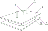
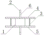
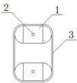
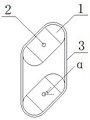
As shown in the attached figures 1-15, the present invention comprises a turntable 1, a rotating shaft 2, an annular belt 3, two parallel upper seal plates 4, a lower seal plate 5 and a liquid pipe 6, wherein the turntable 1 is a square table, two ends of the turntable 1 are symmetrical arc structures, the turntable 1 is provided with two annular belts 3 which are sleeved outside the two turntables 1, the turntable 1 tensions the annular belt 3, the width of the annular belt 3 is equal to the thickness of the turntable 1, the upper seal plates 4 are arranged on the two turntables 1, the lower seal plates 5 are arranged at the bottoms of the two turntables 1, the upper seal plates 4 and the lower seal plates 5 are both provided with rotating shaft holes, the rotating shaft 2 is respectively and fixedly arranged at the top center and the bottom center of the turntable 1, the rotating shaft 2 at the top center of the turntable 1 passes through the rotating shaft hole of the upper seal plate 4, the rotating shaft 2 at the bottom center of the turntable 1 passes through the rotating shaft hole, liquid pipe 6 is located 4 tops of last shrouding and 5 bottoms of shrouding down respectively, and liquid pipe 6 and liquid district intercommunication.
Preferably, the liquid tube 6 of the upper closure plate 4 is provided with a check valve.
Preferably, the rotating directions of the two rotating shafts 2 are the same, the rotating angle of the rotary table 1 is alpha, the alpha is more than or equal to 0 degree and less than or equal to 90 degrees, the arc-shaped structure is semi-cylindrical, the semi-cylindrical structure is beneficial to the attachment of annular belts, and the length of the rotary table 1 is equal to the distance between the middle points of the axes of the two rotary tables 1.
Preferably, the rotating shaft hole of the upper sealing plate 4 and the rotating shaft hole of the lower sealing plate 5 corresponding to one of the rotating tables 1 are waist-shaped holes; the waist-shaped hole is convenient for the rotating shaft to move, so that the position of the rotary table 1 is adjusted, and the purpose of adjusting the tensioning degree of the annular belt 3 is achieved.
Preferably, still include curb plate 7, boss 8, curb plate 7 is located annular area 3 both sides respectively, boss 8 sets firmly in curb plate 7 medial surface, go up shrouding 4 both sides respectively with 8 top rigid couplings of corresponding boss, 5 both sides of lower shrouding respectively with 8 bottom rigid couplings of corresponding boss.
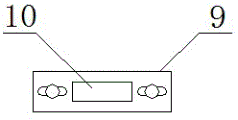
Preferably, the device also comprises a fixing piece 9, fixing rods 10 and bearings 11, wherein the rotating shaft 2 at the center of the top of the rotary table 1 and the rotating shaft 2 at the center of the bottom of the rotary table 1 are respectively provided with the bearings 11, the fixing rods 10 are respectively fixedly arranged at two sides of the outer ring of the bearing 11, the end parts of the fixing rods 10 are fixedly connected with the center of the fixing piece 9, the mounting holes of the fixing piece 9 are connected with the mounting holes of the side plate 7 through bolts, and the mounting holes of the fixing piece 9 at the end parts of the fixing rods 10 corresponding to the; fixing member 9, dead lever 10, bearing 11 constitute firm structure jointly, do benefit to pivot 2 on the one hand and stably rotate, and on the other hand can remove dead lever 10 through the bolt of unscrewing fixing member 9 waist shape hole to remove revolving stage 1, adjust the tensioning degree of annular area 3.
Preferably, the device further comprises a fixed tripod 12, a connecting rod 13 and a push-pull tripod 14, wherein the fixed tripod 12 is fixedly arranged on each fixing rod 10 corresponding to the waist-shaped rotating shaft hole of the upper sealing plate 4 and the waist-shaped rotating shaft hole of the lower sealing plate 5 respectively, one end of the connecting rod 13 is fixedly connected with the fixed tripod 12, the other end of the connecting rod 13 is fixedly connected with the push-pull tripod 14, and the fixed tripod 12 and the push-pull tripod 14 are both horizontal; the upper and lower push-pull tripods 14 jointly form a push-pull structure, so that the rotary table 1 is stably pushed, pulled and adjusted.
Preferably, the device further comprises a gear transmission mechanism, the gear transmission mechanism comprises a gear 15, a supporting cross rod 16, a sliding sleeve 17 and a moving rod 18, the gear 15 is arranged at the upper end of the rotating shaft 2, at least 2 supporting cross rods 16 are respectively arranged on the side plates 7 in a spanning mode, the sliding sleeve 17 is fixedly arranged on the supporting cross rod 16, the moving rod 18 penetrates through the sliding sleeve 17, two racks 19 are arranged on the rod body of the moving rod 18, and the racks 19 correspond to and are meshed with the gears 15 one by one; the two rotary tables 1 can be driven to synchronously rotate through the gear transmission mechanism, so that the liquid area is stably deformed.
Preferably, the movable rod 18 comprises two sub-rods 18a, the end of the sub-rod 18a is provided with an L-shaped joint 18b, the L-shaped joint 18b is provided with a kidney-shaped hole, the two sub-rods 18a are jointed through the L-shaped joint 18b, and the two kidney-shaped holes are connected through bolts; the assembled length-adjustable structure of the movable rod 18 moves the sub-rod 18a together with the corresponding gear 15, the rotating shaft 2 and the turntable 1 when adjusting the tension degree of the endless belt.
Preferably, the device also comprises a fixed frame 20, and the outer side surface of the side plate 7 is fixedly connected with the inner side of the fixed frame 20.
Preferably, the device further comprises an installation frame 21 and a displacement adjusting mechanism, the displacement adjusting mechanism comprises an installation cross rod 22, a moving cross rod 23, a guide cross rod 24, an installation vertical rod 25, a screw rod 26 and an adjusting nut 27, a cross beam 28 is fixedly arranged in the installation frame 21, the installation cross rod 22 is positioned in the installation frame 21, the installation cross rod 22 is parallel to the cross beam 28, two ends of the installation cross rod 22 are respectively and fixedly provided with the guide cross rod 24, the guide cross rod 24 is perpendicular to the installation cross rod 22, the guide cross rod 24 penetrates through the cross beam 28, one end of the moving cross rod 23 is fixedly connected with the middle part of the installation cross rod 22, the other end of the moving cross rod 23 penetrates through the cross beam 28, the moving cross rod 23 is parallel to the guide cross rod 24, the installation cross rod 22, the moving cross rod 23 and the guide cross rod 24 are positioned at the same horizontal, a known connection structure in which the movable cross bar 23 is kept from rotating, for example, a screw 26 is connected with the movable cross bar 23 through a ball hinge; the other end of the screw rod 26 is fixedly provided with an adjusting nut 27, the screw rod 26 penetrates through a threaded hole in the side surface of the mounting frame 21, the mounting upright rod 25 is vertically and fixedly arranged in the middle of the mounting cross rod 22, and the upper end and the lower end of the mounting upright rod 25 penetrate through the corresponding push-pull tripod 14 respectively; the guide cross rod 24 can enable the movable cross rod to stably move, prevent the displacement adjusting mechanism from inclining left and right, and keep stable forward movement or retreat, so that the two push-pull tripods 14 are stably pulled or pushed, the operation is convenient, and the tensioning degree of the annular belt can be conveniently adjusted.
Preferably, the side of the mounting frame 21 is fixedly connected with the side of the fixing frame 20.
Preferably, the device also comprises a rotating shaft braking device, the rotating shaft braking device comprises mounting tables 29 and telescopic loop bars 30, the top of the rotating shaft 2 is of a trapezoidal structure 31, a screw rod 32 is vertically and fixedly arranged at the top of the rotating shaft 2, the center of the bottom of the mounting table 29 is provided with an embedded groove 33 corresponding to the trapezoidal structure 31 in shape, the number of the mounting tables 29 is two, one end of each telescopic loop bar 30 is fixedly connected with the side surface of one of the mounting tables 29, the other end of each telescopic loop bar is fixedly connected with the side surface of the other mounting table 29, the embedded groove 33 of each mounting table 29 is sleeved on the trapezoidal structure 31, the screw rod 32 penetrates through; the rotating shaft braking device enables the two rotary tables to be in a parallel state all the time when the displacement adjusting mechanism adjusts the tensioning degree of the annular belt on one hand, and on the other hand, the mechanism can be prevented from working due to accidental starting.
The working principle and the working process of the invention are as follows: the liquid pipe 6 of the upper sealing plate 4 is connected with a liquid supply pipe, the liquid pipe 6 of the lower sealing plate 5 is connected with a liquid outlet pipe, the end part of the moving rod 18 can be hinged with a connecting rod 34, and the connecting rod 34 is driven by a motor with a crankshaft, so that the moving rod 18 can move back and forth;
before the mechanism is used, the annular belt is tensioned and adjusted, specifically, the bolt of the fixing piece 9 is unscrewed, and the bolts of the waist-shaped holes of the two sub-rods 18a are unscrewed; then, the screw 26 is screwed to rotate through the adjusting nut 27, so that the displacement adjusting mechanism retreats, the displacement adjusting mechanism pulls the fixed tripod 12, the connecting rod 13 and the push-pull tripod 14, namely pulls the fixed rod 10 connected with the fixed tripod 12, namely pulls the rotating shaft 2 and the rotary table 1 to move, and the annular belt 3 is tensioned; then, the bolt of the fixing piece 9 is screwed down to fix the fixing piece 9, and the bolts of the waist-shaped holes of the two sub-rods 18a are screwed down to fix the sub-rods 18 a;
when the mechanism is used, the fastening nut on the screw rod 32 is screwed off, and then the rotating shaft braking device is taken down; the movable rod 18 continuously reciprocates, and the sliding sleeve 17 and the support cross rod 16 jointly form a support guide structure, so that the movable rod 18 stably moves; in the advancing process of the moving rod 18, the rack 19 drives the rotating shaft 2 and the two rotary tables 1 to rotate in the same direction through the gear 15, so that the liquid area is deformed, the liquid in the liquid area is extruded out from the liquid pipe 6 and the liquid outlet pipe at the bottom of the lower sealing plate 5, and the amount of the extruded liquid can be controlled by controlling the rotating angle of the rotary tables 1; the movable rod 18 is then retracted and the liquid supply tube again injects liquid into the liquid region while the liquid region returns to its original shape.
The present invention will be further described with reference to examples 1 to 10.
Example 1
The liquid extrusion mechanism comprises a rotary table 1, a rotary shaft 2, an annular belt 3, an upper sealing plate 4, a lower sealing plate 5 and a liquid pipe 6, wherein the rotary table 1 is a square table, two ends of the rotary table 1 are of symmetrical arc structures, the rotary table 1 is provided with two parallel plates, the annular belt 3 is sleeved outside the two rotary tables 1, the rotary table 1 tensions the annular belt 3, the width of the annular belt 3 is equal to the thickness of the rotary table 1, the upper sealing plate 4 is arranged on the two rotary tables 1, the lower sealing plate 5 is arranged at the bottom of the two rotary tables 1, the upper sealing plate 4 and the lower sealing plate 5 are both provided with rotary shaft holes, the rotary shaft 2 is fixedly arranged at the top center and the bottom center of the rotary table 1 respectively, the rotary shaft 2 at the top center of the rotary table 1 penetrates through the rotary shaft hole of the upper sealing plate 4, the rotary shaft 2 at the bottom center of the rotary table 1 penetrates through the rotary shaft hole of the lower sealing plate 5, a, a liquid pipe 6 communicates with the liquid zone.
Example 2
The liquid extrusion mechanism comprises a rotary table 1, a rotary shaft 2, an annular belt 3, an upper sealing plate 4, a lower sealing plate 5 and a liquid pipe 6, wherein the rotary table 1 is a square table, two ends of the rotary table 1 are of symmetrical arc structures, the rotary table 1 is provided with two parallel plates, the annular belt 3 is sleeved outside the two rotary tables 1, the rotary table 1 tensions the annular belt 3, the width of the annular belt 3 is equal to the thickness of the rotary table 1, the upper sealing plate 4 is arranged on the two rotary tables 1, the lower sealing plate 5 is arranged at the bottom of the two rotary tables 1, the upper sealing plate 4 and the lower sealing plate 5 are both provided with rotary shaft holes, the rotary shaft 2 is fixedly arranged at the top center and the bottom center of the rotary table 1 respectively, the rotary shaft 2 at the top center of the rotary table 1 penetrates through the rotary shaft hole of the upper sealing plate 4, the rotary shaft 2 at the bottom center of the rotary table 1 penetrates through the rotary shaft hole of the lower sealing plate 5, a, the liquid pipe 6 is communicated with the liquid area; the rotating directions of the two rotating shafts 2 are the same, the rotating angle of the rotary table 1 is alpha, the alpha is more than or equal to 0 degree and less than or equal to 90 degrees, the arc-shaped structure is semi-cylindrical, and the length of the rotary table 1 is equal to the distance between the middle points of the axes of the two rotary tables 1.
Example 3
The liquid extrusion mechanism comprises a rotary table 1, a rotary shaft 2, an annular belt 3, an upper sealing plate 4, a lower sealing plate 5 and a liquid pipe 6, wherein the rotary table 1 is a square table, two ends of the rotary table 1 are of symmetrical arc structures, the rotary table 1 is provided with two parallel plates, the annular belt 3 is sleeved outside the two rotary tables 1, the rotary table 1 tensions the annular belt 3, the width of the annular belt 3 is equal to the thickness of the rotary table 1, the upper sealing plate 4 is arranged on the two rotary tables 1, the lower sealing plate 5 is arranged at the bottom of the two rotary tables 1, the upper sealing plate 4 and the lower sealing plate 5 are both provided with rotary shaft holes, the rotary shaft 2 is fixedly arranged at the top center and the bottom center of the rotary table 1 respectively, the rotary shaft 2 at the top center of the rotary table 1 penetrates through the rotary shaft hole of the upper sealing plate 4, the rotary shaft 2 at the bottom center of the rotary table 1 penetrates through the rotary shaft hole of the lower sealing plate 5, a, the liquid pipe 6 is communicated with the liquid area; the rotating directions of the two rotating shafts 2 are the same, the rotating angle of the rotary table 1 is alpha, the alpha is more than or equal to 0 degree and less than or equal to 90 degrees, the arc-shaped structure is semi-cylindrical, and the length of the rotary table 1 is equal to the distance between the middle points of the axes of the two rotary tables 1; the rotating shaft hole of the upper sealing plate 4 and the rotating shaft hole of the lower sealing plate 5 corresponding to one of the rotary tables 1 are waist-shaped holes.
Example 4
The liquid extrusion mechanism comprises a rotary table 1, a rotary shaft 2, an annular belt 3, an upper sealing plate 4, a lower sealing plate 5 and a liquid pipe 6, wherein the rotary table 1 is a square table, two ends of the rotary table 1 are of symmetrical arc structures, the rotary table 1 is provided with two parallel plates, the annular belt 3 is sleeved outside the two rotary tables 1, the rotary table 1 tensions the annular belt 3, the width of the annular belt 3 is equal to the thickness of the rotary table 1, the upper sealing plate 4 is arranged on the two rotary tables 1, the lower sealing plate 5 is arranged at the bottom of the two rotary tables 1, the upper sealing plate 4 and the lower sealing plate 5 are both provided with rotary shaft holes, the rotary shaft 2 is fixedly arranged at the top center and the bottom center of the rotary table 1 respectively, the rotary shaft 2 at the top center of the rotary table 1 penetrates through the rotary shaft hole of the upper sealing plate 4, the rotary shaft 2 at the bottom center of the rotary table 1 penetrates through the rotary shaft hole of the lower sealing plate 5, a, the liquid pipe 6 is communicated with the liquid area; the rotating directions of the two rotating shafts 2 are the same, the rotating angle of the rotary table 1 is alpha, the alpha is more than or equal to 0 degree and less than or equal to 90 degrees, the arc-shaped structure is semi-cylindrical, and the length of the rotary table 1 is equal to the distance between the middle points of the axes of the two rotary tables 1; the rotating shaft hole of the upper sealing plate 4 and the rotating shaft hole of the lower sealing plate 5 corresponding to one of the rotary tables 1 are waist-shaped holes;
the novel annular band is characterized by further comprising side plates 7 and bosses 8, wherein the side plates 7 are located on two sides of the annular band 3 respectively, the bosses 8 are fixedly arranged on the inner side surfaces of the side plates 7, two sides of the upper sealing plate 4 are fixedly connected with the tops of the corresponding bosses 8 respectively, and two sides of the lower sealing plate 5 are fixedly connected with the bottoms of the corresponding bosses 8 respectively.
Example 5
The liquid extrusion mechanism comprises a rotary table 1, a rotary shaft 2, an annular belt 3, an upper sealing plate 4, a lower sealing plate 5 and a liquid pipe 6, wherein the rotary table 1 is a square table, two ends of the rotary table 1 are of symmetrical arc structures, the rotary table 1 is provided with two parallel plates, the annular belt 3 is sleeved outside the two rotary tables 1, the rotary table 1 tensions the annular belt 3, the width of the annular belt 3 is equal to the thickness of the rotary table 1, the upper sealing plate 4 is arranged on the two rotary tables 1, the lower sealing plate 5 is arranged at the bottom of the two rotary tables 1, the upper sealing plate 4 and the lower sealing plate 5 are both provided with rotary shaft holes, the rotary shaft 2 is fixedly arranged at the top center and the bottom center of the rotary table 1 respectively, the rotary shaft 2 at the top center of the rotary table 1 penetrates through the rotary shaft hole of the upper sealing plate 4, the rotary shaft 2 at the bottom center of the rotary table 1 penetrates through the rotary shaft hole of the lower sealing plate 5, a, the liquid pipe 6 is communicated with the liquid area; the rotating directions of the two rotating shafts 2 are the same, the rotating angle of the rotary table 1 is alpha, the alpha is more than or equal to 0 degree and less than or equal to 90 degrees, the arc-shaped structure is semi-cylindrical, and the length of the rotary table 1 is equal to the distance between the middle points of the axes of the two rotary tables 1; the rotating shaft hole of the upper sealing plate 4 and the rotating shaft hole of the lower sealing plate 5 corresponding to one of the rotary tables 1 are waist-shaped holes;
the novel annular band is characterized by further comprising side plates 7 and bosses 8, wherein the side plates 7 are located on two sides of the annular band 3 respectively, the bosses 8 are fixedly arranged on the inner side surfaces of the side plates 7, two sides of the upper sealing plate 4 are fixedly connected with the tops of the corresponding bosses 8 respectively, and two sides of the lower sealing plate 5 are fixedly connected with the bottoms of the corresponding bosses 8 respectively.
The rotary table is characterized by further comprising a fixing piece 9, fixing rods 10 and bearings 11, wherein the bearings 11 are respectively arranged on the rotating shaft 2 at the center of the top of the rotary table 1 and the rotating shaft 2 at the center of the bottom of the rotary table 1, the fixing rods 10 are respectively fixedly arranged on two sides of an outer ring of each bearing 11, the end portions of the fixing rods 10 are fixedly connected with the center of the fixing piece 9, mounting holes of the fixing pieces 9 are connected with mounting holes of the side plates 7 through bolts, and the mounting holes of the fixing pieces 9, corresponding to the rotating shafts penetrating through the.
Example 6
The liquid extrusion mechanism comprises a rotary table 1, a rotary shaft 2, an annular belt 3, an upper sealing plate 4, a lower sealing plate 5 and a liquid pipe 6, wherein the rotary table 1 is a square table, two ends of the rotary table 1 are of symmetrical arc structures, the rotary table 1 is provided with two parallel plates, the annular belt 3 is sleeved outside the two rotary tables 1, the rotary table 1 tensions the annular belt 3, the width of the annular belt 3 is equal to the thickness of the rotary table 1, the upper sealing plate 4 is arranged on the two rotary tables 1, the lower sealing plate 5 is arranged at the bottom of the two rotary tables 1, the upper sealing plate 4 and the lower sealing plate 5 are both provided with rotary shaft holes, the rotary shaft 2 is fixedly arranged at the top center and the bottom center of the rotary table 1 respectively, the rotary shaft 2 at the top center of the rotary table 1 penetrates through the rotary shaft hole of the upper sealing plate 4, the rotary shaft 2 at the bottom center of the rotary table 1 penetrates through the rotary shaft hole of the lower sealing plate 5, a, the liquid pipe 6 is communicated with the liquid area; the rotating directions of the two rotating shafts 2 are the same, the rotating angle of the rotary table 1 is alpha, the alpha is more than or equal to 0 degree and less than or equal to 90 degrees, the arc-shaped structure is semi-cylindrical, and the length of the rotary table 1 is equal to the distance between the middle points of the axes of the two rotary tables 1; the rotating shaft hole of the upper sealing plate 4 and the rotating shaft hole of the lower sealing plate 5 corresponding to one of the rotary tables 1 are waist-shaped holes;
the novel annular band is characterized by further comprising side plates 7 and bosses 8, wherein the side plates 7 are located on two sides of the annular band 3 respectively, the bosses 8 are fixedly arranged on the inner side surfaces of the side plates 7, two sides of the upper sealing plate 4 are fixedly connected with the tops of the corresponding bosses 8 respectively, and two sides of the lower sealing plate 5 are fixedly connected with the bottoms of the corresponding bosses 8 respectively.
The fixing device comprises a rotating shaft 2 at the center of the top of the rotating platform 1 and a rotating shaft 2 at the center of the bottom of the rotating platform 1, and is characterized by further comprising a fixing piece 9, fixing rods 10 and bearings 11, wherein the bearings 11 are respectively arranged on the rotating shaft 2 at the center of the top of the rotating platform 1 and the rotating shaft 2 at the center of the bottom of the rotating platform 1, the fixing rods 10 are respectively fixedly arranged on two sides of the outer ring of each bearing 11, the end parts of the fixing rods 10 are fixedly connected with the center of the fixing piece 9, mounting holes of the;
still including fixed tripod 12, connecting rod 13, push-and-pull tripod 14, the dead lever 10 that corresponds respectively in the waist shape pivot hole of going up shrouding 4, the waist shape pivot hole of lower shrouding 5 has all set firmly fixed tripod 12, the one end and the fixed tripod 12 rigid coupling of connecting rod 13, the other end and the fixed tripod 14 rigid coupling of push-and-pull, fixed tripod 12, push-and-pull tripod 14 all are the level form.
Example 7
The liquid extrusion mechanism comprises a rotary table 1, a rotary shaft 2, an annular belt 3, an upper sealing plate 4, a lower sealing plate 5 and a liquid pipe 6, wherein the rotary table 1 is a square table, two ends of the rotary table 1 are of symmetrical arc structures, the rotary table 1 is provided with two parallel plates, the annular belt 3 is sleeved outside the two rotary tables 1, the rotary table 1 tensions the annular belt 3, the width of the annular belt 3 is equal to the thickness of the rotary table 1, the upper sealing plate 4 is arranged on the two rotary tables 1, the lower sealing plate 5 is arranged at the bottom of the two rotary tables 1, the upper sealing plate 4 and the lower sealing plate 5 are both provided with rotary shaft holes, the rotary shaft 2 is fixedly arranged at the top center and the bottom center of the rotary table 1 respectively, the rotary shaft 2 at the top center of the rotary table 1 penetrates through the rotary shaft hole of the upper sealing plate 4, the rotary shaft 2 at the bottom center of the rotary table 1 penetrates through the rotary shaft hole of the lower sealing plate 5, a, the liquid pipe 6 is communicated with the liquid area; the rotating directions of the two rotating shafts 2 are the same, the rotating angle of the rotary table 1 is alpha, the alpha is more than or equal to 0 degree and less than or equal to 90 degrees, the arc-shaped structure is semi-cylindrical, and the length of the rotary table 1 is equal to the distance between the middle points of the axes of the two rotary tables 1; the rotating shaft hole of the upper sealing plate 4 and the rotating shaft hole of the lower sealing plate 5 corresponding to one of the rotary tables 1 are waist-shaped holes;
the novel annular band is characterized by further comprising side plates 7 and bosses 8, wherein the side plates 7 are located on two sides of the annular band 3 respectively, the bosses 8 are fixedly arranged on the inner side surfaces of the side plates 7, two sides of the upper sealing plate 4 are fixedly connected with the tops of the corresponding bosses 8 respectively, and two sides of the lower sealing plate 5 are fixedly connected with the bottoms of the corresponding bosses 8 respectively.
Still include gear drive, gear drive includes gear 15, supports horizontal pole 16, sliding sleeve 17, carriage release lever 18, and 2 upper ends in pivot are equipped with gear 15, it has 2 at least to support horizontal pole 16, strides respectively and locates on curb plate 7, sliding sleeve 17 sets firmly on supporting horizontal pole 16, carriage release lever 18 passes sliding sleeve 17, be equipped with two racks 19 on the 18 body of rod of carriage release lever, rack 19 and 15 one-to-one of gear and mesh mutually.
Example 8
The liquid extrusion mechanism comprises a rotary table 1, a rotary shaft 2, an annular belt 3, an upper sealing plate 4, a lower sealing plate 5 and a liquid pipe 6, wherein the rotary table 1 is a square table, two ends of the rotary table 1 are of symmetrical arc structures, the rotary table 1 is provided with two parallel plates, the annular belt 3 is sleeved outside the two rotary tables 1, the rotary table 1 tensions the annular belt 3, the width of the annular belt 3 is equal to the thickness of the rotary table 1, the upper sealing plate 4 is arranged on the two rotary tables 1, the lower sealing plate 5 is arranged at the bottom of the two rotary tables 1, the upper sealing plate 4 and the lower sealing plate 5 are both provided with rotary shaft holes, the rotary shaft 2 is fixedly arranged at the top center and the bottom center of the rotary table 1 respectively, the rotary shaft 2 at the top center of the rotary table 1 penetrates through the rotary shaft hole of the upper sealing plate 4, the rotary shaft 2 at the bottom center of the rotary table 1 penetrates through the rotary shaft hole of the lower sealing plate 5, a, the liquid pipe 6 is communicated with the liquid area; the rotating directions of the two rotating shafts 2 are the same, the rotating angle of the rotary table 1 is alpha, the alpha is more than or equal to 0 degree and less than or equal to 90 degrees, the arc-shaped structure is semi-cylindrical, and the length of the rotary table 1 is equal to the distance between the middle points of the axes of the two rotary tables 1; the rotating shaft hole of the upper sealing plate 4 and the rotating shaft hole of the lower sealing plate 5 corresponding to one of the rotary tables 1 are waist-shaped holes;
the novel annular band is characterized by further comprising side plates 7 and bosses 8, wherein the side plates 7 are located on two sides of the annular band 3 respectively, the bosses 8 are fixedly arranged on the inner side surfaces of the side plates 7, two sides of the upper sealing plate 4 are fixedly connected with the tops of the corresponding bosses 8 respectively, and two sides of the lower sealing plate 5 are fixedly connected with the bottoms of the corresponding bosses 8 respectively.
The gear transmission mechanism comprises gears 15, supporting cross rods 16, sliding sleeves 17 and moving rods 18, the gears 15 are arranged at the upper ends of the rotating shafts 2, at least 2 supporting cross rods 16 are respectively arranged on the side plates 7 in a spanning mode, the sliding sleeves 17 are fixedly arranged on the supporting cross rods 16, the moving rods 18 penetrate through the sliding sleeves 17, two racks 19 are arranged on rod bodies of the moving rods 18, and the racks 19 correspond to and are meshed with the gears 15 one by one;
the movable rod 18 comprises two sub-rods 18a, the end parts of the sub-rods 18a are L-shaped joints 18b, the L-shaped joints 18b are provided with waist-shaped holes, the two sub-rods 18a are connected through the L-shaped joints 18b in an overlapping mode, and the two waist-shaped holes are connected through bolts.
Example 9
The liquid extrusion mechanism comprises a rotary table 1, a rotary shaft 2, an annular belt 3, an upper sealing plate 4, a lower sealing plate 5 and a liquid pipe 6, wherein the rotary table 1 is a square table, two ends of the rotary table 1 are of symmetrical arc structures, the rotary table 1 is provided with two parallel plates, the annular belt 3 is sleeved outside the two rotary tables 1, the rotary table 1 tensions the annular belt 3, the width of the annular belt 3 is equal to the thickness of the rotary table 1, the upper sealing plate 4 is arranged on the two rotary tables 1, the lower sealing plate 5 is arranged at the bottom of the two rotary tables 1, the upper sealing plate 4 and the lower sealing plate 5 are both provided with rotary shaft holes, the rotary shaft 2 is fixedly arranged at the top center and the bottom center of the rotary table 1 respectively, the rotary shaft 2 at the top center of the rotary table 1 penetrates through the rotary shaft hole of the upper sealing plate 4, the rotary shaft 2 at the bottom center of the rotary table 1 penetrates through the rotary shaft hole of the lower sealing plate 5, a, the liquid pipe 6 is communicated with the liquid area; the rotating directions of the two rotating shafts 2 are the same, the rotating angle of the rotary table 1 is alpha, the alpha is more than or equal to 0 degree and less than or equal to 90 degrees, the arc-shaped structure is semi-cylindrical, and the length of the rotary table 1 is equal to the distance between the middle points of the axes of the two rotary tables 1; the rotating shaft hole of the upper sealing plate 4 and the rotating shaft hole of the lower sealing plate 5 corresponding to one of the rotary tables 1 are waist-shaped holes;
the novel annular band is characterized by further comprising side plates 7 and bosses 8, wherein the side plates 7 are located on two sides of the annular band 3 respectively, the bosses 8 are fixedly arranged on the inner side surfaces of the side plates 7, two sides of the upper sealing plate 4 are fixedly connected with the tops of the corresponding bosses 8 respectively, and two sides of the lower sealing plate 5 are fixedly connected with the bottoms of the corresponding bosses 8 respectively.
The fixing device comprises a rotating shaft 2 at the center of the top of the rotating platform 1 and a rotating shaft 2 at the center of the bottom of the rotating platform 1, and is characterized by further comprising a fixing piece 9, fixing rods 10 and bearings 11, wherein the bearings 11 are respectively arranged on the rotating shaft 2 at the center of the top of the rotating platform 1 and the rotating shaft 2 at the center of the bottom of the rotating platform 1, the fixing rods 10 are respectively fixedly arranged on two sides of the outer ring of each bearing 11, the end parts of the fixing rods 10 are fixedly connected with the center of the fixing piece 9, mounting holes of the;
the fixing device is characterized by further comprising a fixing tripod 12, a connecting rod 13 and a push-pull tripod 14, wherein the fixing rods 10 corresponding to the waist-shaped rotating shaft hole of the upper sealing plate 4 and the waist-shaped rotating shaft hole of the lower sealing plate 5 are fixedly provided with the fixing tripod 12, one end of the connecting rod 13 is fixedly connected with the fixing tripod 12, the other end of the connecting rod 13 is fixedly connected with the push-pull tripod 14, and the fixing tripod 12 and the push-pull tripod 14 are horizontal;
the device further comprises an installation frame 21 and a displacement adjusting mechanism, the displacement adjusting mechanism comprises an installation cross rod 22, a movable cross rod 23, a guide cross rod 24, an installation vertical rod 25, a screw rod 26 and an adjusting nut 27, a cross beam 28 is fixedly arranged in the installation frame 21, the installation cross rod 22 is positioned in the installation frame 21 and parallel to the cross beam 28, the guide cross rod 24 is fixedly arranged at each of two ends of the installation cross rod 22 respectively, the guide cross rod 24 is perpendicular to the installation cross rod 22 and penetrates through the cross beam 28, one end of the movable cross rod 23 is fixedly connected with the middle of the installation cross rod 22, the other end of the movable cross rod passes through the cross beam 28, the movable cross rod 23 is parallel to the guide cross rod 24, the installation cross rod 22, the movable cross rod 23 and the guide cross rod 24 are positioned at the same horizontal position, one end of the screw rod 26 is rotatably connected with, the mounting upright stanchions 25 are vertically and fixedly arranged in the middle of the mounting cross rod 22, and the upper ends and the lower ends of the mounting upright stanchions 25 respectively penetrate through the corresponding push-pull tripods 14.
Example 10
The liquid extrusion mechanism comprises a rotary table 1, a rotary shaft 2, an annular belt 3, an upper sealing plate 4, a lower sealing plate 5 and a liquid pipe 6, wherein the rotary table 1 is a square table, two ends of the rotary table 1 are of symmetrical arc structures, the rotary table 1 is provided with two parallel plates, the annular belt 3 is sleeved outside the two rotary tables 1, the rotary table 1 tensions the annular belt 3, the width of the annular belt 3 is equal to the thickness of the rotary table 1, the upper sealing plate 4 is arranged on the two rotary tables 1, the lower sealing plate 5 is arranged at the bottom of the two rotary tables 1, the upper sealing plate 4 and the lower sealing plate 5 are both provided with rotary shaft holes, the rotary shaft 2 is fixedly arranged at the top center and the bottom center of the rotary table 1 respectively, the rotary shaft 2 at the top center of the rotary table 1 penetrates through the rotary shaft hole of the upper sealing plate 4, the rotary shaft 2 at the bottom center of the rotary table 1 penetrates through the rotary shaft hole of the lower sealing plate 5, a, the liquid pipe 6 is communicated with the liquid area; the rotating directions of the two rotating shafts 2 are the same, the rotating angle of the rotary table 1 is alpha, the alpha is more than or equal to 0 degree and less than or equal to 90 degrees, the arc-shaped structure is semi-cylindrical, and the length of the rotary table 1 is equal to the distance between the middle points of the axes of the two rotary tables 1; the rotating shaft hole of the upper sealing plate 4 and the rotating shaft hole of the lower sealing plate 5 corresponding to one of the rotary tables 1 are waist-shaped holes;
the side plates 7 are respectively positioned at two sides of the annular belt 3, the bosses 8 are fixedly arranged on the inner side surfaces of the side plates 7, two sides of the upper sealing plate 4 are respectively fixedly connected with the tops of the corresponding bosses 8, and two sides of the lower sealing plate 5 are respectively fixedly connected with the bottoms of the corresponding bosses 8;
the fixing device comprises a rotating shaft 2 at the center of the top of the rotating platform 1 and a rotating shaft 2 at the center of the bottom of the rotating platform 1, and is characterized by further comprising a fixing piece 9, fixing rods 10 and bearings 11, wherein the bearings 11 are respectively arranged on the rotating shaft 2 at the center of the top of the rotating platform 1 and the rotating shaft 2 at the center of the bottom of the rotating platform 1, the fixing rods 10 are respectively fixedly arranged on two sides of the outer ring of each bearing 11, the end parts of the fixing rods 10 are fixedly connected with the center of the fixing piece 9, mounting holes of the;
the fixing device is characterized by further comprising a fixing tripod 12, a connecting rod 13 and a push-pull tripod 14, wherein the fixing rods 10 corresponding to the waist-shaped rotating shaft hole of the upper sealing plate 4 and the waist-shaped rotating shaft hole of the lower sealing plate 5 are fixedly provided with the fixing tripod 12, one end of the connecting rod 13 is fixedly connected with the fixing tripod 12, the other end of the connecting rod 13 is fixedly connected with the push-pull tripod 14, and the fixing tripod 12 and the push-pull tripod 14 are horizontal;
still include gear drive, gear drive includes gear 15, supports horizontal pole 16, sliding sleeve 17, carriage release lever 18, and 2 upper ends in pivot are equipped with gear 15, it has 2 at least to support horizontal pole 16, strides respectively and locates on curb plate 7, sliding sleeve 17 sets firmly on supporting horizontal pole 16, carriage release lever 18 passes sliding sleeve 17, be equipped with two racks 19 on the 18 body of rod of carriage release lever, rack 19 and 15 one-to-one of gear and mesh mutually.
The movable rod 18 comprises two sub-rods 18a, the end parts of the sub-rods 18a are L-shaped joints 18b, the L-shaped joints 18b are provided with waist-shaped holes, the two sub-rods 18a are connected with each other through the L-shaped joints 18b in an overlapping mode, and the two waist-shaped holes are connected through bolts;
the device further comprises an installation frame 21 and a displacement adjusting mechanism, the displacement adjusting mechanism comprises an installation cross rod 22, a movable cross rod 23, a guide cross rod 24, an installation vertical rod 25, a screw rod 26 and an adjusting nut 27, a cross beam 28 is fixedly arranged in the installation frame 21, the installation cross rod 22 is positioned in the installation frame 21 and parallel to the cross beam 28, the guide cross rod 24 is fixedly arranged at each of two ends of the installation cross rod 22 respectively, the guide cross rod 24 is perpendicular to the installation cross rod 22 and penetrates through the cross beam 28, one end of the movable cross rod 23 is fixedly connected with the middle of the installation cross rod 22, the other end of the movable cross rod passes through the cross beam 28, the movable cross rod 23 is parallel to the guide cross rod 24, the installation cross rod 22, the movable cross rod 23 and the guide cross rod 24 are positioned at the same horizontal position, one end of the screw rod 26 is rotatably connected with, the mounting upright stanchions 25 are vertically and fixedly arranged in the middle of the mounting cross rod 22, and the upper ends and the lower ends of the mounting upright stanchions 25 respectively penetrate through the corresponding push-pull tripods 14;
still include pivot arresting gear, pivot arresting gear includes mount table 29, flexible loop bar 30, 2 tops of pivot are trapezium structure 31, 2 tops of pivot are vertical to have set firmly lead screw 32, mount table 29 bottom center is equipped with the embedded groove 33 corresponding with the trapezium structure 31 shape, mount table 29 has two, 30 one end of flexible loop bar and 29 side rigid couplings of one of them mount table, the other end and 29 side rigid couplings of another mount table, the embedded groove 33 cover of mount table 29 is on trapezium structure 31, and lead screw 32 passes mount table 29, be equipped with fastening nut on the lead screw 32.