CN112572995A - Conducting rod supporting device for transporting gas insulation wall bushing - Google Patents
Conducting rod supporting device for transporting gas insulation wall bushing Download PDFInfo
- Publication number
- CN112572995A CN112572995A CN202011332662.0A CN202011332662A CN112572995A CN 112572995 A CN112572995 A CN 112572995A CN 202011332662 A CN202011332662 A CN 202011332662A CN 112572995 A CN112572995 A CN 112572995A
- Authority
- CN
- China
- Prior art keywords
- rod
- support
- conducting rod
- clamping block
- end cover
- Prior art date
- Legal status (The legal status is an assumption and is not a legal conclusion. Google has not performed a legal analysis and makes no representation as to the accuracy of the status listed.)
- Granted
Links
Images


Classifications
-
- B—PERFORMING OPERATIONS; TRANSPORTING
- B65—CONVEYING; PACKING; STORING; HANDLING THIN OR FILAMENTARY MATERIAL
- B65D—CONTAINERS FOR STORAGE OR TRANSPORT OF ARTICLES OR MATERIALS, e.g. BAGS, BARRELS, BOTTLES, BOXES, CANS, CARTONS, CRATES, DRUMS, JARS, TANKS, HOPPERS, FORWARDING CONTAINERS; ACCESSORIES, CLOSURES, OR FITTINGS THEREFOR; PACKAGING ELEMENTS; PACKAGES
- B65D67/00—Kinds or types of packaging elements not otherwise provided for
Landscapes
- Engineering & Computer Science (AREA)
- Mechanical Engineering (AREA)
- Insulators (AREA)
Abstract
The invention relates to a transportation auxiliary tool of a gas insulation wall bushing, in particular to a conducting rod supporting device for transporting the gas insulation wall bushing. The conducting rod supporting device for transporting the gas insulation wall bushing adopts the following technical scheme: conducting rod strutting arrangement is used in transportation of gas insulation wall bushing includes: the cylinder body connecting end cover is provided with a bolt through hole and is used for being fixed at an orifice flange on the outer peripheral surface of the axial middle part of the sleeve body through a bolt; the conducting rod support is used for supporting the lower part of the conducting rod in the sleeve body; the upper end of the supporting rod is connected to the conducting rod support, and the lower end of the supporting rod is connected to the end cover of the connecting end of the cylinder body and used for transmitting supporting force.
Description
Technical Field
The invention relates to a transportation auxiliary tool of a gas insulation wall bushing, in particular to a conducting rod supporting device for transporting the gas insulation wall bushing.
Background
The gas insulation wall bushing comprises a bushing body and a conducting rod, wherein the conducting rod is coaxially arranged in the bushing body, end flanges are arranged at two ends of the bushing body, the conducting rod is directly connected with the end flanges through a fastener, or is connected with the end flanges through conductive contact fingers and other electric connection modes. The gas insulated wall bushing is generally assembled in a manufacturing facility and transported to an installation site for installation.
However, after the gas insulation wall bushing assembly is completed, the gravity of the conducting rod is completely borne by the flanges at the two end parts, the conducting rod is long in length, the conducting rod is very easy to vibrate in transportation, and the conducting rod is easy to wear, deform or even break.
Disclosure of Invention
The invention aims to provide a conducting rod supporting device for transporting a gas insulation wall bushing, which solves the problems that the conducting rod of the existing gas insulation wall bushing is easy to vibrate, wear, deform and even break.
The conductive rod supporting device for transporting the gas insulation wall bushing adopts the following technical scheme:
conducting rod strutting arrangement is used in transportation of gas insulation wall bushing includes:
the cylinder body connecting end cover is provided with a bolt through hole and is used for being fixed at an orifice flange on the outer peripheral surface of the axial middle part of the sleeve body through a bolt;
the conducting rod support is used for supporting the lower part of the conducting rod in the sleeve body;
and the upper end of the supporting rod is connected to the conducting rod support, and the lower end of the supporting rod is connected to the end cover connected with the barrel body and used for transmitting supporting force.
Has the advantages that: by adopting the technical scheme, the end cover is connected with the sleeve body through the barrel, the conducting rod support can utilize the support rod to realize the support of the conducting rod, so that the axial middle part of the conducting rod forms a fulcrum, the problem of vibration of the conducting rod with longer length in transportation is solved, the problems of abrasion, deformation and even fracture of the conducting rod are solved, the product quality can be effectively guaranteed, and the transportation cost is reduced.
As a preferred technical scheme: a support rod inserting hole is formed in the connecting end cover of the cylinder body, and the lower end of the support rod is inserted into the support rod inserting hole;
the lower extreme of bracing piece is equipped with the external screw thread, is equipped with support nut on the external screw thread, and support nut is used for supporting the top mouth edge of bracing piece jack is last.
Has the advantages that: by adopting the technical scheme, the supporting position can be flexibly adjusted through the supporting nut, the reliable supporting of the conducting rod is better ensured, and the universality is good.
As a preferred technical scheme: the support rod insertion hole is a through hole for the lower end of the support rod to penetrate through the cylinder body connecting end cover;
the conductive rod supporting device for transporting the gas insulation wall bushing further comprises a sealing nut, wherein a threaded blind hole is formed in the sealing nut and is used for being connected to the penetrating part of the supporting rod in a threaded mode;
the end face of one end of the threaded blind hole on the sealing nut and the lower side face of the end cover connected with the barrel are provided with a nut sealing ring or a nut sealing gasket.
Has the advantages that: by adopting the technical scheme, the sealing nut is arranged, so that the requirement on the air tightness of certain pressure gas inside a product in the transportation process can be better met.
As a preferred technical scheme: and a sealing ring groove is formed in the end face of one end of the sealing nut, which is provided with the threaded blind hole, and the nut sealing ring is arranged in the sealing ring groove.
Has the advantages that: by adopting the technical scheme, the sealing performance is favorably improved.
As a preferred technical scheme: and an end cover sealing ring or an end cover sealing gasket is arranged between the cylinder connecting end cover and the orifice flange on the peripheral surface of the sleeve body.
Has the advantages that: adopt above-mentioned technical scheme can further guarantee sealed effect.
As a preferred technical scheme: and a sealing ring groove is formed in the upper side face of the barrel connecting end cover, and the end cover sealing ring is arranged in the sealing ring groove.
Has the advantages that: by adopting the technical scheme, the sealing performance is favorably improved.
As a preferred technical scheme: the upper end of the supporting rod is provided with a small-diameter section which is a threaded section; the small-diameter section forms a shaft shoulder at the upper end of the supporting rod, and the shaft shoulder is used for pressing the conductive rod support so as to realize fixation with the conductive rod support.
Has the advantages that: by adopting the technical scheme, the conducting rod supporting device is convenient to process and assemble, and the conducting rod support is convenient to be arranged in the sleeve body.
As a preferred technical scheme: the conductive rod support comprises an upper clamping block and a lower clamping block, an arc-shaped groove is formed in one side, close to each other, of the upper clamping block and the lower clamping block, and the arc-shaped groove is used for being clamped on the conductive rod;
the conducting rod support also comprises a locking piece, and the locking piece is used for locking the upper clamping block and the lower clamping block so as to enable the conducting rod support to be clamped and fixed on the conducting rod.
Has the advantages that: by adopting the technical scheme, the conductive rod can be completely fixed, and a better vibration reduction effect is achieved.
As a preferred technical scheme: the upper clamping block and the lower clamping block are arranged in a split mode from top to bottom, the locking piece is a bolt assembly, and the bolt assembly penetrates through the upper clamping block and the lower clamping block simultaneously to enable the conducting rod support to tightly hold the conducting rod.
Has the advantages that: by adopting the technical scheme, the structure is simple, and the sleeve is convenient to be arranged in the sleeve body.
As a preferred technical scheme: and a cushion layer is arranged at the arc-shaped groove.
Has the advantages that: adopt above-mentioned technical scheme can play the guard action to the conducting rod.
For the subject to be protected by the present patent, each preferred technical solution under the same subject may be adopted alone, and when the preferred technical solutions under the same subject can be combined, two or more preferred technical solutions under the same subject may be arbitrarily combined, and the technical solutions formed by the combination are not specifically described here, and are included in the description of the present patent in this form.
Drawings
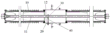
FIG. 1 is a schematic view showing a state of use of an embodiment 1 of a conductive rod supporting device for gas-insulated wall bushing transportation according to the present invention;
FIG. 2 is a side view of the conductive rod support apparatus for transporting the gas-insulated wall bushing of FIG. 1, as viewed in the axial direction of the wall bushing of FIG. 1;
fig. 3 is a partially enlarged view of a portion a in fig. 2.
The names of the components corresponding to the corresponding reference numerals in the drawings are: 10. a sleeve body 10; 11. a conductive rod; 12. an orifice flange; 20. the cylinder body is connected with an end cover; 21. a support rod jack; 22. an end cap seal ring; 30. a conductive rod support; 31. an upper clamping block; 32. a lower clamping block; 33. an arc-shaped slot; 34. locking the bolt; 35. a cushion layer; 40. a support bar; 41. a support nut; 42. a sealing nut; 43. and a nut sealing ring.
Detailed Description
In order to make the objects, technical solutions and advantages of the present invention more apparent, the present invention is described in further detail below with reference to the accompanying drawings and embodiments. It should be understood that the detailed description and specific examples, while indicating the preferred embodiment of the invention, are intended for purposes of illustration only and are not intended to limit the scope of the invention. The components of embodiments of the present invention generally described and illustrated in the figures herein may be arranged and designed in a wide variety of different configurations.
Thus, the following detailed description of the embodiments of the present invention, presented in the figures, is not intended to limit the scope of the invention, as claimed, but is merely representative of selected embodiments of the invention. All other embodiments, which can be derived by a person skilled in the art from the embodiments of the present invention without making any creative effort, shall fall within the protection scope of the present invention.
It is noted that relational terms such as "first" and "second," and the like, which may be present in the embodiments of the present invention, are used solely to distinguish one entity or action from another entity or action without necessarily requiring or implying any actual such relationship or order between such entities or actions. Also, the terms "comprises," "comprising," or any other variation thereof, are intended to cover a non-exclusive inclusion, such that a process, method, article, or apparatus that comprises a list of elements does not include only those elements but may include other elements not expressly listed or inherent to such process, method, article, or apparatus. Without further limitation, the statement that "comprises an … …" is intended to indicate that there are additional elements of the same process, method, article, or apparatus that comprise the element.
In the description of the present invention, unless otherwise expressly specified or limited, the terms "mounted," "connected," and "connected" when they are used are to be construed broadly, e.g., as meaning a fixed connection, a removable connection, or an integral connection; can be mechanically or electrically connected; either directly or indirectly through intervening media, or may be interconnected between two elements. The specific meaning of the above terms in the present invention can be understood by those skilled in the art from specific situations.
In the description of the present invention, unless otherwise specifically stated or limited, the term "provided" may be used in a broad sense, for example, the object of "provided" may be a part of the body, or may be arranged separately from the body and connected to the body, and the connection may be detachable or non-detachable. The specific meaning of the above terms in the present invention can be understood by those skilled in the art from specific situations.
The present invention will be described in further detail with reference to examples.
Embodiment 1 of the conductive rod supporting device for gas insulation wall bushing transportation in the present invention:
as shown in fig. 1, the conducting rod supporting device for transporting a bushing body includes a cylinder connecting end cover 20, a conducting rod support 30 and a supporting rod 40, which are used for the bushing body 10 shown in fig. 1, and support the conducting rod 11 when transporting the bushing body 10.
The cylinder connecting end cover 20 is a circular plate-shaped structure, and bolt through holes are formed in the edge of the cylinder connecting end cover and are used for being fixed to the orifice flange 12 on the outer peripheral surface of the axial middle portion of the sleeve body 10 through bolts. In this embodiment, the casing body 10 is provided at the middle thereof with a pressure detection hole, the cylinder connection end cap 20 is an end cap for corresponding to the orifice flange 12 of the pressure detection hole, and the conductor bar support 30 and the support bar 40 have a size set to be fitted into the casing body 10 from the pressure detection hole. Of course, in other implementations, the orifice flange 12 may be an orifice flange for other purposes than the pressure detection hole, and the orifice flange may be located at the middle of the sleeve body 10 in the axial direction, or may be biased to one end of the sleeve body 10, and the whole may be located at the middle of the sleeve body 10 in the axial direction. As shown in fig. 3, a support rod insertion hole 21 is formed at the center of the cylinder connection end cover 20, and the support rod insertion hole 21 is a through hole for inserting and passing through the lower end of the support rod 40. The upper side face of the cylinder body connecting end cover 20 is provided with a sealing ring groove, an end cover sealing ring 22 is arranged in the sealing ring groove, and the sealing ring is used for being in sealing fit with the outer side face of the orifice flange 12 on the outer peripheral face of the sleeve pipe body 10, so that the requirement on the air tightness of gas with certain pressure in the product in the transportation process is met. Of course, in other implementations, the end cap seal ring 22 may be replaced with an end cap seal.
As shown in fig. 2, the conducting rod support 30 includes an upper clamping block 31 and a lower clamping block 32, the upper clamping block 31 and the lower clamping block 32 are separately arranged up and down, an arc-shaped groove 33 is provided at a side where the upper clamping block 31 and the lower clamping block 32 are close to each other, and the arc-shaped groove 33 is used for being clamped on the conducting rod 11. Bolt through holes are formed in the upper clamping block 31 and the lower clamping block 32 and on two sides of the arc-shaped groove 33, corresponding locking bolts 34 can penetrate through the bolt through holes, and the locking bolts 34 form locking parts used for locking the upper clamping block 31 and the lower clamping block 32 to enable the conducting rod support 30 to be clamped and fixed on the conducting rod 11, so that the conducting rod 11 in the sleeve body 10 is supported. In order to avoid damaging the conductive rod 11, a cushion 35 is disposed at the arc-shaped groove 33.
The bottom surface of the lower clamping block 32 is provided with a threaded hole, the upper end of the support rod 40 is provided with a small-diameter section, the small-diameter section is a threaded section, a shaft shoulder is formed at the upper end of the support rod 40, and the shaft shoulder is used for being pressed onto the lower clamping block 32 of the conducting rod support 30 to be fixed with the conducting rod support 30. As shown in fig. 2 and 3, the lower end of the support rod 40 is provided with an external thread, and a support nut 41 is arranged on the external thread, and the support nut 41 is used for supporting the top opening edge of the support rod insertion hole 21. The lower end of the support rod 40 penetrates through the cylinder connecting end cover 20 downwards, the penetrating part is connected with a sealing nut 42 through threads, and a threaded blind hole for connecting the support rod 40 is formed in the top end face of the sealing nut 42, so that the supporting force is transmitted between the cylinder connecting end cover 20 and the conducting rod support 30. And a sealing ring groove is formed in the end face of one end of the sealing nut 42, which is provided with the threaded blind hole, and a nut sealing ring 43 is arranged in the sealing ring groove and used for forming sealing fit with the lower side face of the barrel connecting end cover 20. Of course, in other embodiments, the nut seal 43 may be replaced with a nut seal.
After the product assembly is completed, the upper clamping block 31 and the lower clamping block 32 are respectively installed at the conducting rod 11 through the pressure detection hole of the sleeve body 10, the locking bolt 34 is installed at the conducting rod 11, the supporting rod 40 and the lower clamping block 32 are fixed through threaded connection, the supporting nut 41 is screwed to a proper position, the barrel connecting end cover 20 is sleeved on the supporting rod 40, the barrel connecting end cover is installed on the pressure detection hole of the sleeve body 10, then the sealing nut 42 is installed, the supporting rod 40 supports and fixes the conducting rod 11 in place along with the screwing fixation of the sealing nut 42, and the rigid fixation of the conducting rod 11 is realized. After the installation site is reached, the conducting rod supporting device is detached according to the reverse order, the pressure detection device is installed on the pressure detection hole, only partial parts of the product need to be disassembled, and the product structure can be quickly restored and installed for use, so that the product quality can be effectively guaranteed, and the transportation cost is reduced.
Embodiment 2 of the conductive rod supporting device for gas insulation wall bushing transportation in the present invention:
the difference between the embodiment and embodiment 1 is that in embodiment 1, the conducting rod support 30 includes an upper clamping block 31 and a lower clamping block 32, and the upper clamping block 31 and the lower clamping block 32 are separately arranged up and down and can be clamped and fixed on the conducting rod 11; in the embodiment, the conductive rod support 30 is not provided with the upper clamping block 31, and only supports the conductive rod 11. Due to the gravity action of the conducting rod 11, when vibration occurs in the transportation process, the conducting rod 11 has smaller upward vibration and larger downward vibration under the action of the gravity of the conducting rod 11, so that the abrasion, deformation and even fracture failure of the conducting rod 11 can be reduced only by using the lower clamping block 32 as a support.
In other embodiments, the upper clamping block 31 and the lower clamping block 32 may be hinged at one end and locked at the other end by the locking bolt 34.
Embodiment 3 of the conductive rod supporting device for gas insulation wall bushing transportation in the present invention:
the difference between this embodiment and embodiment 1 is that in embodiment 1, the support rod insertion hole 21 of the cylinder connecting end cap 20 for inserting the support rod 40 is a through hole, whereas in this embodiment, the support rod insertion hole 21 is a blind hole, and the sealing nut 42 is not required to be provided.
The above description is only a preferred embodiment of the present application, and not intended to limit the present application, the scope of the present application is defined by the appended claims, and all changes in equivalent structure made by using the contents of the specification and the drawings of the present application should be considered as being included in the scope of the present application.
Claims (10)
Priority Applications (1)
| Application Number | Priority Date | Filing Date | Title |
|---|---|---|---|
| CN202011332662.0A CN112572995B (en) | 2020-11-24 | 2020-11-24 | Conducting rod supporting device for transporting gas insulation wall bushing |
Applications Claiming Priority (1)
| Application Number | Priority Date | Filing Date | Title |
|---|---|---|---|
| CN202011332662.0A CN112572995B (en) | 2020-11-24 | 2020-11-24 | Conducting rod supporting device for transporting gas insulation wall bushing |
Publications (2)
| Publication Number | Publication Date |
|---|---|
| CN112572995A true CN112572995A (en) | 2021-03-30 |
| CN112572995B CN112572995B (en) | 2023-04-18 |
Family
ID=75123260
Family Applications (1)
| Application Number | Title | Priority Date | Filing Date |
|---|---|---|---|
| CN202011332662.0A Active CN112572995B (en) | 2020-11-24 | 2020-11-24 | Conducting rod supporting device for transporting gas insulation wall bushing |
Country Status (1)
| Country | Link |
|---|---|
| CN (1) | CN112572995B (en) |
Cited By (1)
| Publication number | Priority date | Publication date | Assignee | Title |
|---|---|---|---|---|
| CN115224653A (en) * | 2021-04-19 | 2022-10-21 | 河南平芝高压开关有限公司 | A fixing tool for busbar conductive rod |
Citations (7)
| Publication number | Priority date | Publication date | Assignee | Title |
|---|---|---|---|---|
| EP0181955A2 (en) * | 1983-11-24 | 1986-05-28 | Mitsubishi Denki Kabushiki Kaisha | Electric connector |
| EP0196348A1 (en) * | 1985-04-02 | 1986-10-08 | Hitachi, Ltd. | Gas insulated electrical apparatus |
| KR100920147B1 (en) * | 2009-05-06 | 2009-10-05 | (주)간삼파트너스 종합건축사사무소 | Piping Pipe Support Structure for Power Distribution |
| CN104143801A (en) * | 2013-09-26 | 2014-11-12 | 国家电网公司 | Conducting rod supporting structure and pipeline bus using same |
| CN106848964A (en) * | 2016-11-11 | 2017-06-13 | 上海谙培电气有限公司 | A kind of 35kv all insulations enclosed busbar |
| CN109709444A (en) * | 2018-11-30 | 2019-05-03 | 平顶山学院 | A kind of transmission facility |
| CN211351624U (en) * | 2019-12-30 | 2020-08-25 | 江苏龙腾电力设备制造有限公司 | Transition main bus insulation support device |
-
2020
- 2020-11-24 CN CN202011332662.0A patent/CN112572995B/en active Active
Patent Citations (7)
| Publication number | Priority date | Publication date | Assignee | Title |
|---|---|---|---|---|
| EP0181955A2 (en) * | 1983-11-24 | 1986-05-28 | Mitsubishi Denki Kabushiki Kaisha | Electric connector |
| EP0196348A1 (en) * | 1985-04-02 | 1986-10-08 | Hitachi, Ltd. | Gas insulated electrical apparatus |
| KR100920147B1 (en) * | 2009-05-06 | 2009-10-05 | (주)간삼파트너스 종합건축사사무소 | Piping Pipe Support Structure for Power Distribution |
| CN104143801A (en) * | 2013-09-26 | 2014-11-12 | 国家电网公司 | Conducting rod supporting structure and pipeline bus using same |
| CN106848964A (en) * | 2016-11-11 | 2017-06-13 | 上海谙培电气有限公司 | A kind of 35kv all insulations enclosed busbar |
| CN109709444A (en) * | 2018-11-30 | 2019-05-03 | 平顶山学院 | A kind of transmission facility |
| CN211351624U (en) * | 2019-12-30 | 2020-08-25 | 江苏龙腾电力设备制造有限公司 | Transition main bus insulation support device |
Cited By (1)
| Publication number | Priority date | Publication date | Assignee | Title |
|---|---|---|---|---|
| CN115224653A (en) * | 2021-04-19 | 2022-10-21 | 河南平芝高压开关有限公司 | A fixing tool for busbar conductive rod |
Also Published As
| Publication number | Publication date |
|---|---|
| CN112572995B (en) | 2023-04-18 |
Similar Documents
| Publication | Publication Date | Title |
|---|---|---|
| CN105492093A (en) | Terminal head for sheathed temperature measurement sensor | |
| KR20090070801A (en) | Pipe fixture | |
| CN100368720C (en) | Sleeve for cable entries and pipe penetrations | |
| CN107482545A (en) | The pipeline body of super adaptation | |
| CN112572995B (en) | Conducting rod supporting device for transporting gas insulation wall bushing | |
| CN204284677U (en) | A kind of thread threading sealing fixing device | |
| KR20140044347A (en) | Self- tightning pipe clamp | |
| CN113757475A (en) | Connecting structure of air storage tank and air pipeline and mounting and dismounting method | |
| CN202120758U (en) | Capacitor fixing device used to fix capacitor on installation plate | |
| CN107249093B (en) | A flameproof camera with damping installation | |
| CN218267967U (en) | Pipeline heat insulation device | |
| CN110661227A (en) | Cable lead-in device and explosion-proof equipment | |
| CN210053195U (en) | An explosion-proof cable gland | |
| US830501A (en) | Protecting-bushing for electric-circuit wires. | |
| CN201730906U (en) | Tube end connecting and fixing structure of elastic rubber tube | |
| JP5190657B2 (en) | Position detection switch mounting mechanism in fluid pressure equipment | |
| CN206374750U (en) | For the suspension frame component being installed to vestibule diaphragm on car body | |
| WO2019019271A1 (en) | Pass-through part for hydraulic control pipe of remote control valve | |
| CN106402549B (en) | Assembling pipe joint | |
| CN204828962U (en) | Manufacturing equipment and manufacturing equipment pipeline threading device thereof | |
| JP2023519993A5 (en) | ||
| CN222108336U (en) | A dustproof, waterproof and explosion-proof electrical box introduction device | |
| CN216279866U (en) | Fixed anti-rotation structure for pipe connection | |
| CN205715096U (en) | Set pipe mounting structure | |
| CN111952922B (en) | Lead device and pressure vessel with same |
Legal Events
| Date | Code | Title | Description |
|---|---|---|---|
| PB01 | Publication | ||
| PB01 | Publication | ||
| SE01 | Entry into force of request for substantive examination | ||
| SE01 | Entry into force of request for substantive examination | ||
| GR01 | Patent grant | ||
| GR01 | Patent grant |