Line with sensor for detecting disturbances associated with the line
Technical Field
The invention relates to a line for electrical connection in a magnetic resonance tomography device, having a connection to the magnetic resonance tomography device.
Background
Magnetic resonance tomography apparatuses are imaging devices which, for imaging an examination subject, align the nuclear spins of the examination subject with a strong external magnetic field and excite the nuclear spins to precess around this alignment by means of an alternating magnetic field. Precession or return of spins from this excited state to a state with less energy in response in turn produces an alternating magnetic field, which is received via an antenna.
These signals are position-encoded by means of gradient magnetic fields, which position-encoding subsequently enables the received signals to be correlated with the volume elements. The received signals are then analyzed and a three-dimensional imaging representation of the examination object is provided. For receiving the signals, receiving antennas, so-called local coils, which are arranged directly on the examination subject for achieving a better signal-to-noise ratio, are preferably used. The receiving antenna may also be mounted in the patient bed.
Magnetic resonance tomography apparatuses require high-frequency shielding in two respects. On the one hand, to excite the nuclear spins, high-frequency pulses with a power in the kilowatt range are generated, which are only partially absorbed in the patient. Radio waves leaving the patient channel (Patientendrchufxurung) radiate into the space and must therefore be shielded in order to comply with emission limits.
In contrast, the magnetic resonance signals to be received for imaging are extremely weak. In order to achieve a sufficient signal-to-noise ratio (SNR), external interference signals need to be masked.
Therefore, in the prior art, an expensive shielding room is installed around the magnetic resonance tomography apparatus to reduce emissions and radiation contamination.
Disclosure of Invention
The object of the invention is therefore to reduce the overhead for masking.
The above-mentioned object is achieved by a circuit according to the invention and a magnetic resonance tomography apparatus according to the invention.
The circuit according to the invention is provided for electrical connection in a magnetic resonance tomography apparatus and has an electrical conductor which can conduct an electrical current. By means of the electrical conductivity, the conductor also serves as an antenna for electromagnetic waves, so that electrical interference can be received or emitted capacitively or inductively and also be transmitted along its extent, for example into the shielded region. The line according to the invention has a connection line, for example a fixed electrical connection or an electrical plug connection, to the magnetic resonance tomography apparatus.
The line has interfering electrical conductors. An interference electrical conductor is to be understood as a conductor, by the arrangement or connection of which an interference signal can be transmitted. Any signal which does not contribute to the image detection and which may impair the quality of the image provided is considered to be a disturbing signal in the sense of the present invention. That is, it is also possible here to refer to signals which, although required for image acquisition, do not carry image information directly. Examples are power lines, control lines, communication lines, devices communicating with the patient for example, or disturbances on the lighting device within the patient tunnel. However, lines directly related to the image generation, such as gradient coil connections, Shim current lines (Shim-Stromleitung) and their signals, for example, can also lead to artifacts in the image detection, in the sense that these also disturb the conductors.
The interference electrical conductor can also be a conductor of a line which is actually provided for protecting the signal line of the line against interference signals. For example, the outer conductor of the coaxial line itself as a conductor may also introduce interference signals into the shielded room. Multiple conductors or cores of a line may also be interfering conductors.
Here, the interference conductor is designed to be characterized by receiving electromagnetic interference signals from the environment and/or radiating electromagnetic interference signals into the environment, only given that it can be realized by the electrical properties and arrangement of the interference conductor, and the interference conductor is thus a potential source of interference. However, in the sense of the claims, the interfering conductor is absolutely not subjected to an additional interfering signal or is absolutely not required to be subjected to an additional interfering signal.
Furthermore, the line according to the invention has a sensor which is electrically and/or magnetically coupled to the interfering line. Different embodiments of the coupling that can be envisaged are given in detail below.
The sensor is connected or connectable to the magnetic resonance tomography device via a signal connection, by means of which the received interference signals can be relayed from the interference conductor to a controller of the magnetic resonance tomography device. This enables the controller to identify and suppress the interfering signals in the magnetic resonance signals thus known.
The connection line with the sensor according to the invention advantageously makes it possible to detect and/or detect the interference signal on the line as far as possible at the source or at a location which separates the interference signal on the line from the useful signal well, so that the interference signal can then be effectively suppressed in the image detection.
Further advantageous embodiments are given below.
In one possible embodiment of the circuit according to the invention, the sensor has a coil or an induction coil for inductive coupling to the interference conductor. In this case, the coils are preferably aligned with a face which is enclosed by one or more coil windings and is substantially perpendicular to magnetic field vectors which are generated by currents of the interference signals on the interference signal conductors. Here, when the angle enclosed by the normal vector of the surface and the magnetic field vector is less than 30 degrees, 20 degrees, or 10 degrees, it is regarded as substantially perpendicular.
The inductive coupling by means of the coil advantageously provides electrically isolated coupling to the interfering conductor.
In a conceivable embodiment of the connection line according to the invention, the interference conductor is arranged in a plane enclosed by the one or more coil windings.
The arrangement around the line enables a simple mechanical fixing and is insensitive to small position changes.
In one possible embodiment of the circuit according to the invention, the coil is a loop coil surrounding the interference conductor. In other words, the conductor of the coil is wound around a ring in a closed trajectory, which in turn surrounds the interfering conductor and/or the line. The ring shape can be a solid or hollow winding body or can merely provide an imaginary geometry in which the conductor of the coil is wound. In this case, the annular part is preferably free of ferrites or other materials which are unsuitable for large magnetic fields or which would otherwise impair the magnetic resonance measurement.
In an advantageous manner, the toroidal coil is particularly sensitive to magnetic fields which are generated by the interference conductor through which the current flows and which annularly surround the interference conductor, and at the same time allows an electrically and mechanically robust fixation.
In a conceivable embodiment of the circuit according to the invention, the sensor has a capacitive coupling element for coupling to the interference conductor. For example, planar conductive elements are conceivable which are pressed onto the line in a manner separated by a dielectric, either as a tube or as two half-shells surrounding the line.
In an advantageous manner, the capacitive coupling is particularly sensitive to disturbances of which the source has a high impedance.
In one embodiment of the circuit according to the invention, it is conceivable for the sensor to have a directional coupler. Any coupling device which provides a signal as a coupling element in relation to the propagation direction of an interference signal on an interference conductor is understood to be a directional coupler. The directional coupler may be implemented, for example, by a stripline parallel to the disturbing conductor or transformer.
The directional coupler can distinguish whether the signal is coming from the local coil or moving in the direction of the local coil. When disturbances traveling in the direction of the local coil are problematic in image detection, the parasitic magnetic resonance signals only lead to artifacts when they are mistakenly regarded as disturbance signals and an attempt is made to compensate for them. The directional coupler here makes it possible to separate the two signals in an advantageous manner and to suppress only interfering signals.
In one possible embodiment of the circuit according to the invention, the sensor resonates at the larmor frequency of the magnetic resonance tomography device. Here, the magnetic resonance frequency of the nuclear spins to be detected in the static magnetic field B0 of the magnetic resonance tomography apparatus is referred to as the larmor frequency. In the case of inductive coupling by means of a coil, the resonance can be achieved, for example, by a capacitance connected to the coil.
For imaging, in a magnetic resonance tomography apparatus, magnetic resonance signals of nuclear spins having a larmor frequency are detected. Therefore, image detection is particularly sensitive to interference with this frequency. By means of the sensor resonating at this frequency, particularly important interference signals can be detected again with greater amplitude and thus better.
In a conceivable embodiment of the circuit according to the invention, the sensor has a protection for the excitation pulses of the magnetic resonance tomography apparatus. Excitation pulses for nuclear spins with a power of maximum kw at the larmor frequency, in particular in the case of sensors which resonate at this frequency, can lead to damage to the input element. The sensor can therefore have, for example, a passive diode for voltages above the cut-off voltage at which a short circuit occurs. Active circuitry that detunes the sensor under control of the controller may also be used.
In an advantageous manner, the protective element prevents damage to the sensor caused by the magnetic resonance tomography apparatus.
In a possible embodiment of the magnetic resonance tomography apparatus according to the invention, the sensor is arranged adjacent to the patient path. The patient path is thereby assigned a position at which the magnetic resonance signals are received for the detection of the image, which is therefore particularly sensitive to interference. Here, distances smaller than 50%, 20%, or 10% of the length of the line or the vacuum wavelength of the radio waves at the larmor frequency of the magnetic resonance tomography apparatus are considered to be adjacent.
In an advantageous manner, the arrangement of the sensor on a line near or adjacent to the patient tunnel ensures that as little interference as possible is injected between the sensor and the patient tunnel, which interference is not detected by the sensor.
Drawings
The above described features, characteristics and advantages of the present invention and its implementation will become clearer and more easily understood in conjunction with the description of the embodiments described in detail below with reference to the attached drawings.
Figure 1 shows a schematic view of a magnetic resonance tomography apparatus with a circuit according to the invention;
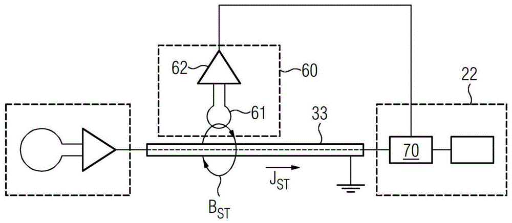
FIG. 2 shows a schematic view of an embodiment of a circuit with a sensor according to the invention;
FIG. 3 shows a schematic view of an embodiment of a circuit with a sensor according to the invention;
FIG. 4 shows a schematic diagram of an embodiment of a circuit with a sensor according to the invention;
FIG. 5 shows a schematic view of an embodiment of a circuit with a sensor according to the invention;
FIG. 6 shows a schematic view of a sensor according to an embodiment of the circuit of the invention;
fig. 7 shows a schematic view of a sensor according to an embodiment of the circuit of the invention.
Detailed Description
Fig. 1 shows a schematic illustration of an embodiment of a magnetic resonance tomography apparatus 1, the magnetic resonance tomography apparatus 1 having a line 33 according to the invention with a sensor 60.
The magnet unit 10 has a field magnet 11, which field magnet 11 generates a static magnetic field B0 in the acquisition region for aligning the nuclear spins of the sample or patient 100. The recording region is characterized by an extremely homogeneous static magnetic field B0, the homogeneity being related in particular to the magnetic field strength or the magnitude. The recording area is almost spherical and is arranged in a patient tunnel 16, which patient tunnel 16 extends through the magnet unit 10 in the longitudinal direction 2. The patient bed 30 is movable in the patient tunnel 16 by a movement unit 36. The field magnet 11 is typically a superconducting magnet that can provide a magnetic field with a flux density of up to 3T, even higher with the latest devices. However, for lower field strengths, permanent magnets or electromagnets with normally conducting coils may also be used.
Furthermore, the magnet unit 10 has a gradient coil 12, the gradient coil 12 being designed for superimposing the magnetic field B0 with the variable magnetic field in three spatial directions for spatial discrimination of an imaging region in the acquired examination volume. The gradient coils 12 are typically coils of normally conductive wire, which can generate mutually orthogonal fields in the examination volume.
The magnet unit 10 also has a body coil 14, the body coil 14 being designed for radiating high-frequency signals fed via signal conductors into the examination volume, receiving resonance signals emitted by the patient 100, and outputting via the signal conductors.
The control unit 20 supplies the magnet unit 10 with different signals for the gradient coil 12 and the body coil 14 and analyzes the received signals.
The control unit 20 therefore has a gradient controller 21, the gradient controller 21 being designed for supplying variable currents to the gradient coils 12 via the feed lines, the variable currents providing the desired gradient fields in the examination volume in a time-coordinated manner.
Furthermore, the control unit 20 has a radio-frequency unit 22, the radio-frequency unit 22 being designed for generating radio-frequency pulses having a predetermined temporal profile, amplitude and spectral power distribution for exciting magnetic resonances of the nuclear spins in the patient 100. In this case, pulse powers in the kilowatt range can be achieved. The excitation pulses can be radiated into the patient 100 by the body coil 14 or else by a local transmitting antenna.
The controller 23 communicates with the gradient controller 21 and the high frequency unit 22 via a signal bus 25.
A local coil 50 is arranged on the patient 100, the local coil 50 being connected to the radio-frequency unit 22 and its receiver 70 via a line 33. It is also conceivable, however, for the magnetic resonance signals to be received by the body coil 14 and forwarded to the receiver 70.
The patient passageways preferably have a radius R, which applies:
R<(LambdaL*1.841)/(2*Pi)
here, LambdaLThe wavelength of the radio waves in the air at the larmor frequency of the magnetic resonance tomography apparatus 1 is given. If the radius R is smaller than the term on the right, the radio waves propagate in the patient channel 16 in an exponentially decaying manner and the interference signal strongly decays in the center of the examination region FoV. LambdaLAlso known as the limiting wavelength of the circular hollow conductor, and the frequency associated therewith is known as the limiting frequency.
However, electromagnetic signals entering the patient passageway 16 through an electrical conductor such as line 33 do not undergo exponential decay because line 33 acts like a coaxial conductor with the conductive wall of the patient passageway. Interference may enter the shielding of the line 33, for example, through inductance or capacitance outside the patient tunnel 16. The line 33 functions as a disturbing conductor in the sense of the present invention.
The local coil 50 thus receives a mixture of magnetic resonance signals and interference signals, which enter the patient channel 16, in particular via interference conductors. By means of active interference suppression, in which the interference signal is scaled and added with the opposite sign to the signal of the local coil 50 by the receiver 70, the interference signal in the reception signal of the local coil can be reduced or, in the ideal case, completely suppressed. For this purpose, however, the interfering signal itself must be known as accurately as possible. The interference signal portion in the reception signal of the local coil 50 can then be determined, for example, by autocorrelation and, by suitable selection of the phase shift and amplification or attenuation, reduced significantly or eliminated completely.
According to the invention, therefore, the sensor 60 is arranged on the interfering line in order to detect, as far as possible without error, interfering signals which are captured by the interfering line and enter the patient channel 16. In the following, different embodiments of the sensor are shown.
The line 33 between the local coil 50 as interference conductor and the receiver 70 is shown by way of example in fig. 2. Alternating current I induced by electromagnetic interference fieldSTFlows over the outer conductor of the coaxial line. The source may be a device in another room or building. Alternating current ISTIn turn, an alternating magnetic field B is generated which surrounds the signal line 33 or the interfering conductorST. The sensor 60 according to the invention is coupled to the disturbing magnetic field B by means of a coil or induction coil 61STTo utilize it. Ideally, the induction coil 61 is oriented with respect to the disturbing conductor such that the normal vector of the face enclosed by the induction coil 61 coincides with the magnetic field B extending in a circle around the signal lineSTAre oriented in a tangential manner. In this way, the voltage induced into the induction coil 61 is maximal and the sensor 60 provides as large and as little disturbing signal as possible. In addition, the preferred sensor 60 has a low noise preamplifier 62(LNA) in the line passing through the sensor63 forward the sense signal to the receiver 70, the low noise preamplifier 62 amplifies the sense signal. Here, the induction coil 61 may have a plurality of windings to increase the induced voltage. The induction coil 61 is electrically isolated from the interfering conductors.
In principle, instead of coils or induction coils, other sensors 60 are also conceivable which can detect the amplitude and/or phase of the high-frequency alternating magnetic field, for example hall sensors or Josephson contact devices or SQID (superconducting quantum interference device).
Fig. 3 shows another embodiment of a sensor 60 according to the present invention. The sensor 60 is here arranged, by way of example, on a line 31 for supplying energy to an illumination device, for example for the patient tunnel 16.
In this case, the sensor 60 has an induction coil 61, the winding of which is wound around a winding package which surrounds the line 33 or the interference conductor on the outer circumference. It is also conceivable that the winding package itself is virtual, i.e. that the winding is arranged in an unsupported manner without the winding package. In this case, the winding package preferably has the shape of a ring or a cylindrical ring, but it is also conceivable to surround the interference conductor instead of a ring, for example by an ellipse, an oval or a polygon. It is likewise conceivable that the cross section of the winding package and thus the shape of the individual windings of the induction coil 61 is not only circular, but also, for example, likewise oval, polygonal, or has a mixed shape, for example a D-shape. In other words, the individual windings extend around the winding package and are in turn arranged along the circumference around the interference conductor, so that, as shown, the two connections of the induction coil 61 are placed side by side so that they can be returned to the low-noise preamplifier 62 at a small distance and a small closed surface.
Due to the fact that the magnetic field lines B are arranged along the magnetic field linesSTThe magnetic field lines of the largest closed surface that pass extend, so an induction coil 61 with this shape has the largest induced voltage. At the same time, the sensor is susceptible to being pushed away (aufschieben) and is insensitive to position changes and to external interfering signals, i.e. not conducted on interfering conductors.
Fig. 4 shows a further variant. It is assumed here by way of example that the gradient connection lines connecting the controller 20 to the gradient coils 12 are interference lines.
The interference signal is not received by induction, but capacitively by the electric field component of the interference signal. In one possible embodiment, the sensor 60 may have one or, as shown here, two capacitive coupling elements 64. Which is arranged in the vicinity of the insulator of the interference conductor, preferably outside on the insulator of the interference conductor, and is electrically isolated therefrom. In this case, the electric field component of the high-frequency interference propagating along the interference conductor causes a voltage difference which is amplified by the low-noise preamplifier 62 and is supplied to the receiver 70 again. It is also conceivable that only one capacitive coupling element 64 is provided and that the reference potential is the signal ground.
The variant of the sensor shown in fig. 5 again has a directional coupler. In this case, any form of signal collector of the disturbing conductor is considered as a directional coupler, which provides a signal related to the propagation direction of the disturbing signal on the disturbing conductor. This may be a general directional coupler, but also a combination of a plurality of inductive or capacitive coupling elements providing a direction-dependent signal is conceivable.
The directional coupler enables a distinction to be made between signals whose propagation direction is directed away from the local coil 50 and signals that enter the local coil. In an advantageous manner, therefore, parasitic magnetic resonance signals on the outer conductor of the coaxial cable can be distinguished from incoming interference signals, so that magnetic resonance signals are not erroneously identified as interference signals and, during image evaluation, artifacts are not thereby produced as a result of interference suppression.
In the embodiment of fig. 6, the sensor 60 according to the invention has a resonance element 66 in order to make the sensor 60 particularly sensitive to a predetermined frequency, preferably to the larmor frequency of the magnetic resonance tomography apparatus 1. Since the image detection is carried out by means of magnetic resonance signals from the nuclear spins, the frequencies of which correspond to the larmor frequency of the spins in the static magnetic field B0, the image detection reacts particularly sensitively to disturbances in this frequency range. That is to say that here, a better interference suppression is particularly effective and can be achieved by a higher output signal of the sensor 60 in this frequency range. This can be achieved, for example, by the resonance of the sensor having the maximum amplitude at the larmor frequency. For the toroidal coil shown by way of example in fig. 6, this can be achieved by a capacitance as the resonant element 66 in the parallel resonant circuit.
Due to the large dynamic range between the interference signal and the magnetic resonance signal on the one hand and the high-frequency pulse for exciting the nuclear spins on the other hand, in particular in resonance sensors, for example, the sensor, in particular the low-noise amplifier 62, can be damaged due to the large input amplitude during the excitation pulse. Thus, as protection, an active protection element 67, here in the form of a PIN diode, may be provided, which, under the control of the controller 20, reduces the input signal of the low noise amplifier 62. As shown in fig. 6, this can be achieved by the PIN diode acting as a variable capacitance detuning the resonant circuit consisting of the induction coil 61 and the resonant element 66. However, it is also conceivable, for example, for the PIN diode to be operated as a switch which short-circuits the resonant circuit or is detuned by an inserted capacitance or inductance. Other mechanical or electronic switches may be used for this purpose.
Fig. 7 shows a further conceivable embodiment of a sensor 60 with a capacitive coupling element 64, which capacitive coupling element 64 is tuned to the larmor frequency by means of an inductance as a resonant element 66. Also embodied in this figure is an exemplary passive protection element 68 consisting of two anti-parallel diodes that short circuit, and therefore limit, each signal above a threshold voltage.
Other combinations of inductive pickups or inductive coils 61 or capacitive coupling elements 64 with active protection elements 67 and/or passive protection elements 68, respectively, are also conceivable in the sense of the present invention.
While the invention has been shown and described in further detail with reference to preferred embodiments thereof, the invention is not limited to the examples disclosed, and other variations can be derived therefrom by those skilled in the art without departing from the scope of the invention.