CN1126247C - Surface wave device balun resonator filters - Google Patents
Surface wave device balun resonator filters Download PDFInfo
- Publication number
- CN1126247C CN1126247C CN97182188.7A CN97182188A CN1126247C CN 1126247 C CN1126247 C CN 1126247C CN 97182188 A CN97182188 A CN 97182188A CN 1126247 C CN1126247 C CN 1126247C
- Authority
- CN
- China
- Prior art keywords
- resonator
- resonator filter
- filters
- transducer
- filter
- Prior art date
- Legal status (The legal status is an assumption and is not a legal conclusion. Google has not performed a legal analysis and makes no representation as to the accuracy of the status listed.)
- Expired - Fee Related
Links
Images


Classifications
-
- H—ELECTRICITY
- H03—ELECTRONIC CIRCUITRY
- H03H—IMPEDANCE NETWORKS, e.g. RESONANT CIRCUITS; RESONATORS
- H03H9/00—Networks comprising electromechanical or electro-acoustic elements; Electromechanical resonators
- H03H9/0023—Networks for transforming balanced signals into unbalanced signals and vice versa, e.g. baluns, or networks having balanced input and output
- H03H9/0028—Networks for transforming balanced signals into unbalanced signals and vice versa, e.g. baluns, or networks having balanced input and output using surface acoustic wave devices
-
- H—ELECTRICITY
- H03—ELECTRONIC CIRCUITRY
- H03H—IMPEDANCE NETWORKS, e.g. RESONANT CIRCUITS; RESONATORS
- H03H9/00—Networks comprising electromechanical or electro-acoustic elements; Electromechanical resonators
- H03H9/02—Details
- H03H9/125—Driving means, e.g. electrodes, coils
- H03H9/145—Driving means, e.g. electrodes, coils for networks using surface acoustic waves
- H03H9/14502—Surface acoustic wave [SAW] transducers for a particular purpose
- H03H9/14505—Unidirectional SAW transducers
Landscapes
- Physics & Mathematics (AREA)
- Acoustics & Sound (AREA)
- Surface Acoustic Wave Elements And Circuit Networks Thereof (AREA)
- Piezo-Electric Or Mechanical Vibrators, Or Delay Or Filter Circuits (AREA)
Abstract
Description
发明领域field of invention
本发明涉及表面波器件平衡-不平衡转换谐振器滤波器,即在平衡(差动)和不平衡(单端)信号之间提供一种转换的表面波器件谐振器滤波器。本文中所用的术语“表面波”包含声表面波(SAW),它包括泄漏SAW以及表面掠体波。The present invention relates to a balanced-unbalanced conversion resonator filter for a surface wave device, that is, a surface wave device resonator filter that provides a conversion between balanced (differential) and unbalanced (single-ended) signals. As used herein, the term "surface wave" includes surface acoustic waves (SAW), which include leaky SAW as well as surface skimming body waves.
背景技术Background technique
对信号,例如是在无线通信设备的发射机和/或接收机中的RF(射频)和/或IF(中频)信号进行滤波,使用表面波器件谐振器滤波器是众所周知的。同样,对于能提供用来在平衡和不平衡信号之间进行转换的这样一种谐振器滤波器也是众所周知的,因此,避免了将平衡变换器分开的需要。The use of surface wave device resonator filters is well known for filtering signals, such as RF (radio frequency) and/or IF (intermediate frequency) signals in transmitters and/or receivers of wireless communication devices. Also, it is known to provide such a resonator filter for switching between balanced and unbalanced signals, thus avoiding the need for a separate balun.
例如,Saw等人在1994年11月15日发表的美国专利No.5,365,138的题目为“Double Mode Surface Wave Resonators”中描述了一种WCR(波导或横向耦合的谐振器)滤波器,在这种滤波器中,其两个IDT(叉指换能器)中的一个及该滤波器的外部导线条被分为相位相反的两半,用来提供一个平衡的信号接点,而另一个IDT提供了一个不平衡的信号接点,这样滤波器就提供了一种平衡-不平衡转换器的功能。与此相似,LCR(纵向耦合谐振器)滤波器也提供了一种平衡-不平衡转换器的功能,例如在1997年1月3日出版的国际专利申请,公开号No.WO97/00556,题目为“Cascaded Surface Wave Device Filters”中就对它进行了说明。For example, U.S. Patent No. 5,365,138, entitled "Double Mode Surface Wave Resonators," issued by Saw et al. on November 15, 1994, describes a WCR (waveguide or laterally coupled resonator) filter in which In the filter, one of its two IDTs (Interdigital Transducers) and the outer wire strip of the filter are divided into two halves with opposite phases to provide a balanced signal contact, while the other IDT provides An unbalanced signal junction, such that the filter provides a balun function. Similarly, LCR (Longitudinal Coupled Resonator) filters also provide a balun function, such as in International Patent Application Publication No. WO97/00556, published on January 3, 1997, entitled It is described in "Cascaded Surface Wave Device Filters".
由北方电信有限公司在1997年6月4日申请的国际专利申请No.PCT/CA97/00368、题目为“Cascaded Surface Wave Device Filters”的申请中说明并要求保护一种使用了SPUDT(单相单向换能器)或RSPUDT(谐振式SPUDT)的表面波谐振器滤波器。International patent application No.PCT/CA97/00368, entitled "Cascaded Surface Wave Device Filters" filed on June 4, 1997 by Northern Telecom Co., Ltd., describes and claims protection of a device using SPUDT (single-phase single-phase transducer) or RSPUDT (resonant SPUDT) surface wave resonator filter.
本发明的一个目的是使一种表面波器件谐振器滤波器,尤其是一种SPUDT或RSPUDT谐振器滤波器配备平衡-不平衡转换功能。It is an object of the present invention to equip a surface wave device resonator filter, especially a SPUDT or RSPUDT resonator filter, with a balun function.
发明概述Summary of the invention
本发明的一个方面是提供了一种表面波器件平衡-不平衡转换谐振器滤波器,它包括第一表面波器件谐振器滤波器、第二表面波器件谐振器滤波器以及多个信号接点。第一表面波器件谐振器滤波器包括第一和第二换能器,它们中的每一个都具有信号接点和接地接点;第二表面波器件谐振器滤波器包括第一和第二换能器,它们中的每一个都具有信号接点和接地接点,第二谐振器滤波器与第一谐振器滤波器很相似,第二谐振器滤波器的第一和第二换能器的信号接点之间的通道与第一谐振器滤波器的第一和第二换能器的信号接点之间的通道相差180°的相位;第一和第二谐振器滤波器的第一换能器的多个信号接点耦合在一起,从而能构成平衡-不平衡变换器谐振器滤波器的一个不平衡端口,第一和第二谐振器滤波器的第二换能器的多个信号接点构成了平衡-不平衡变换器谐振器滤波器的一个平衡端口。One aspect of the present invention provides a balun resonator filter for a surface wave device, which includes a first resonator filter for a surface wave device, a second resonator filter for a surface wave device, and a plurality of signal contacts. The first surface wave device resonator filter includes first and second transducers each having a signal contact and a ground contact; the second surface wave device resonator filter includes first and second transducers , each of them has a signal contact and a ground contact, the second resonator filter is very similar to the first resonator filter, the signal contact between the first and second transducers of the second resonator filter The channel of the first resonator filter is 180° out of phase with the channel between the signal junctions of the first and second transducers of the first resonator filter; the multiple signals of the first transducer of the first and second resonator filter The contacts are coupled together so as to form an unbalanced port of the balun resonator filter, and the plurality of signal contacts of the second transducers of the first and second resonator filters form the balun A balanced port of the converter resonator filter.
最好是,第一和第二谐振器滤波器中每一个谐振器滤波器的第一和第二换能器中至少一个,以及最好是其中的每一个,都包括一个最好是RSPUDT(谐振SPUDT)的SPUDT(单相单向换能器)。可以很方便地在一个单独的压电衬底上提供第一和第二谐振器滤波器,该衬底包括位于两个谐振器滤波器之间的一条槽,以避免两个谐振器滤波器之间的表面波耦合。第二谐振器滤波器的第一和第二换能器中的一个可以是第一谐振器滤波器的第一和第二换能器中相应的一个换能器的镜像,以提供180°的相位差。Preferably, at least one of, and preferably each of, the first and second transducers of each of the first and second resonator filters includes an RSPUDT ( Resonant SPUDT) of SPUDT (Single Phase Unidirectional Transducer). The first and second resonator filters may conveniently be provided on a single piezoelectric substrate including a slot between the two resonator filters to avoid a gap between the two resonator filters. surface wave coupling between them. One of the first and second transducers of the second resonator filter may be a mirror image of a corresponding one of the first and second transducers of the first resonator filter to provide a 180° Phase difference.
本发明的另一个方面是提供了包括第一和第二SPUDT(单相单向换能器)谐振器滤波器的一种表面波器件,其中每个SPUDT谐振器滤波器都包括第一和第二换能器,该第一和第二谐振器滤波器具有相似的信号通路,且有180°的相位差,第一和第二谐振器滤波器的第一换能器的多个信号接点耦合在一起构成该表面波器件的一个不平衡端口,而第一和第二谐振器滤波器的第二换能器的多个信号接点耦合在一起,构成了该表面波器件的一个平衡端口。Another aspect of the present invention is to provide a surface wave device comprising first and second SPUDT (Single Phase Unidirectional Transducer) resonator filters, wherein each SPUDT resonator filter comprises first and second Two transducers, the first and second resonator filters have similar signal paths, and have a phase difference of 180°, and a plurality of signal contacts of the first transducers of the first and second resonator filters are coupled together form an unbalanced port of the surface wave device, and signal contacts of the second transducers of the first and second resonator filters are coupled together to form a balanced port of the surface wave device.
本发明的进一步的方面是提供了一种表面波器件平衡-不平衡谐振器滤波器,它包括:第一SPUDT(单相单向换能器)谐振器滤波器、第二SPUDT谐振器滤波器、一个不平衡信号接点以及一个平衡信号接点。第一SPUDT谐振器滤波器包括第一和第二换能器;第二SPUDT谐振器滤波器包括第一和第二换能器,除了第二谐振器滤波器的一个换能器是第一谐振器滤波器的一个相应的换能器的镜像之外,第二谐振器滤波器大体上与第一谐振器滤波器相同;不平衡信号接点针对的是第一和第二谐振器滤波器中的第一换能器;平衡的信号接点包括针对第一和第二谐振器滤波器中每一个谐振器滤波器的第二换能器的多个信号接点。A further aspect of the present invention provides a surface wave device balun-unbalanced resonator filter, which includes: the first SPUDT (single-phase unidirectional transducer) resonator filter, the second SPUDT resonator filter , an unbalanced signal contact and a balanced signal contact. The first SPUDT resonator filter includes first and second transducers; the second SPUDT resonator filter includes first and second transducers, except that one transducer of the second resonator filter is the first resonant The second resonator filter is substantially identical to the first resonator filter except that it is a mirror image of a corresponding transducer of the resonator filter; the unbalanced signal contacts are for the first and second resonator filters First transducer; balanced signal contacts comprising a plurality of signal contacts for the second transducer of each of the first and second resonator filters.
附图说明Description of drawings
以下,将通过参照附图进行的说明,使大家能进一步了解本发明,其中:Below, by referring to the description carried out with reference to accompanying drawing, make everyone can further understand the present invention, wherein:
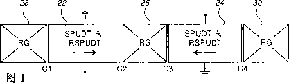
图1图示说明了SPUDE或RSPUDT谐振器滤波器的一般构成;Figure 1 illustrates the general composition of a SPUDE or RSPUDT resonator filter;
图2至4图示说明了谐振器滤波器的各种改进的结构;Figures 2 to 4 illustrate various modified structures of resonator filters;
图5图示说明了谐振器滤波器的一种特定的结构;Figure 5 illustrates a specific structure of a resonator filter;
图6至8图示说明了图5的谐振器滤波器的细节;以及Figures 6 to 8 illustrate details of the resonator filter of Figure 5; and
图9和10图示说明了依据本发明的实施例的提供有平衡-不平衡功能的谐振器滤波器的结构。9 and 10 illustrate the structure of a resonator filter provided with a balun function according to an embodiment of the present invention.
实现本发明的方式The mode of realizing the present invention
参见附图,图1显示了一个SPUDT或一个RSPUDT谐振器滤波器的一般结构。附图的平面代表压电衬底的一个平面。谐振器滤波器包括位于横向反射栅RG 28和30之间的两个排列在表面波传播方向上的SPUDT或RSPUDT 22和24,且这两个SPUDT或REPUDT通过对表面波进行部分反射和部分传输的一个中心反射栅(RG)26耦合。虽然换能器22和24被当作是单向的,但更准确地说,对附图中就每个换能器的箭头所代表的主要的表面波传输方向来说,换能器22和24可以是双向的。图1中还示出了对换能器22和24的不平衡(即信号和地)接点。Referring to the drawings, Figure 1 shows the general structure of a SPUDT or a RSPUDT resonator filter. The plane of the drawing represents one plane of the piezoelectric substrate. The resonator filter includes two SPUDTs or
假定,一开始,换能器22和24是SPUDT,则图1的谐振器滤波器就在换能器和RG之间的过渡区具有四个谐振腔C1到C4。可将这种滤波器设计为(具有用已知方式所提供的输入和/或输出匹配电路的)具有良好的近带抑制以及大体平直的通带,且该滤波器可以提供一个谐振器滤波器的诸如象低插入损耗这样的各种合乎需求的特性,可以提供无TTI(三次行程干扰)并因此有可能有一个无扰动的通带,该滤波器不需要吸声器且容易进行频率调整。这种滤波器可以有一个小的孔径,该孔径例如大约为26λ,其中λ为所传播的表面波的波长,这样压电衬底也可以随之变小。Assuming, initially, that
将RSPUDT用于换能器22和24的用法,使得在设计方面有了进一步的改进,使能更轻易地实现可更准确地定义谐振器滤波器的多种特性的设计,其中每个RSPUDT都具有至少一个内部谐振腔。可将多个不同的谐振腔设计为:在谐振器滤波器的通带内具有轻微不同的谐振频率,以产生一个大体上所需要的包括平直通带和良好近带抑制的滤波器响应。由于对换能器22和24使用了RSPUDT而不是SPUDT,这种做法在滤波器的特性方面提供了所希望的改进,以下的说明将主要针对RSPUDT,但可以理解,一般也可用SPUDT来替换所指的这种RSPUDT。The use of RSPUDTs for
可省去图1谐振器滤波器中的中心RG 26,以生成谐振器滤波器的另一种结构,这种结构如图2所示,在两个横向RG 28和30之间包括两个RSPUDT 22和24。这种谐振器滤波器具有位于RG和RSPUDT之间的过渡区上的三个谐振腔C1、C3和C5,以及在RSPUDT 22、24的每一个之内的至少一个谐振腔C2、C4。The
可通过对RSPUDT 22和24进行加权来替代横向RG 28和30中的一个或两个,以使这两个RG作为外端的反射器,从而可以改善图1和2中的谐振器滤波器的特性;这种加权可包括在后面会进一步说明的变迹法或抽指加权。例如,图3和4分别说明了以这种方式被替代了横向RG 28和30的图1和2的谐振器滤波器。在每一种情况中,每个RSPUDT都被图示为具有一个谐振腔,且用参考号C1、C2等来定义这些谐振腔。The characteristics of the resonator filters in Figures 1 and 2 can be improved by substituting one or both of the
这样,除了RSPUDT 22和RG 28被经过加权的用作反射器的RSPUDT32所替代,以及RSPUDT 24和RG 30被同样经过加权的用作反射器的RSPUDT 34替代以外,图3和4中的谐振器滤波器分别与图1和2中的谐振器滤波器相似,RSPUDT 32在谐振器滤波器的左手或外端,并用竖线表示,RSPUDT 34在谐振器滤波器的右手或外端,并用竖线表示。由于RSPUDT 32和34每一个都有一个谐振腔,这样图3中的谐振器滤波器就有四个谐振腔C1至C4,图4中的谐振器滤波器有三个谐振腔C1至C3。Thus, the resonators in Figs. The filters are similar to the resonator filters in Figures 1 and 2, respectively, with RSPUDT 32 at the left-hand or outer end of the resonator filter and indicated by a vertical bar, and RSPUDT 34 at the right-hand or outer end of the resonator filter and indicated by a vertical bar express. Since
谐振器滤波器的极点数与谐振腔的数目相应;这样,例如图3中的谐振器滤波器就是一个4极点的滤波器。通过适当地选择谐振腔的数目,从而可提供任意所需阶数(极点数)的谐振器滤波器。谐振器滤波器不需要如上定义并如上所述的那样多的谐振腔。例如,对于图2中所示的结构中的谐振器滤波器,它在每个RSPUDT和相应的横向RG 28或30之间,在极性上没有间断性或改变,这样,在这些过渡区没有构成谐振腔(图2中的C1和C5),谐振器滤波器仅仅具有三个谐振腔。The number of poles of the resonator filter corresponds to the number of resonant cavities; thus, for example, the resonator filter in Fig. 3 is a 4-pole filter. By properly selecting the number of resonators, resonator filters of any desired order (number of poles) can be provided. A resonator filter does not require as many resonant cavities as defined above and described above. For example, for a resonator filter in the structure shown in Figure 2, there is no discontinuity or change in polarity between each RSPUDT and the corresponding
如上所述,可以使用变迹法和/或抽指加权对RSPUDT 32和34进行加权。例如可以对图3或4所示的谐振器滤波器的RSPUDT 32和34同时进行抽指加权,也可以对其中的一个使用抽指加权,而对另一个使用变迹法加权。如果每个RSPUDT只提供一个谐振腔,每个RSPUDT可被称作是WWSCR(经抽指加权的单腔RSPUDT)或被称作是一个ASCR(经变迹的单腔RSPUDT)。As noted above, RSPUDTs 32 and 34 may be weighted using apodization and/or fingertip weighting. For example, the RSPUDT 32 and 34 of the resonator filter shown in FIG. 3 or 4 can be simultaneously weighted by finger extraction, or one of them can be weighted by finger extraction, while the other can be weighted by apodization. If each RSPUDT provides only one cavity, each RSPUDT may be referred to as a WWSCR (single cavity RSPUDT abstracted weighted) or as an ASCR (single cavity RSPUDT apodized).
我们已经了解了各种形式的SPUDT,且在如上所述的谐振器滤波器内的每一个RSPUDT或SPUDT都可以具有任意所需的形式。尤其是,在表面波传播方向上占据了一个SPUDT或一个RSPUDT一个波长的每一个基本单元,可包括一个传统的电极宽度控制(EWC)构件,或一个改进了反射率的EWC(IR-EWC)构件(也称作是DART或分布式声反射换能器)。对于每一个基本单元,EWC构件都包括两个分别与地和信号线连接且每一个都有λ/8宽的电极,同时在这两个电极之间存在λ/8的间隙,同时EWC构件还包括连接到地的一个λ/4的电极,因而定义了分隔开3λ/8的换能和反射中心。在IR-EWC构件中,宽电极的宽度增加到3λ/8,且相邻电极间的间隙都为λ/8。后者的优势在于其改进的反射率和相等的间隙。Various forms of SPUDTs are known, and each RSPUDT or SPUDT within a resonator filter as described above can be of any desired form. In particular, each elementary unit occupying one wavelength of one SPUDT or one RSPUDT in the direction of surface wave propagation may include a conventional electrode width control (EWC) member, or an EWC with improved reflectivity (IR-EWC) component (also called DART or Distributed Acoustic Reflectance Transducer). For each basic unit, the EWC component includes two electrodes that are respectively connected to the ground and the signal line and each has a width of λ/8, and there is a gap of λ/8 between the two electrodes, and the EWC component is also A λ/4 electrode is included connected to ground, thus defining transduction and reflection centers separated by 3λ/8. In the IR-EWC structure, the width of the wide electrodes is increased to 3λ/8, and the gaps between adjacent electrodes are all λ/8. The advantage of the latter is its improved reflectivity and equal gap.
就整体而言,就以下参照图5到8所举的例子,对谐振器滤波器的一个特定的结构进行进一步的说明。图5示意性地说明了谐振器滤波器的整体排列,图6到8示意性地显示了分别按图5中的箭头A、B和C所标记的区域中的这一滤波器的细节。In general, a specific structure of a resonator filter will be further described with reference to the examples given below with reference to FIGS. 5 to 8 . Figure 5 schematically illustrates the overall arrangement of a resonator filter, and Figures 6 to 8 schematically show details of this filter in the areas marked by arrows A, B and C in Figure 5, respectively.
参见图5,该谐振器滤波器具有参照图3所说明的结构,该谐振器滤波器有使用了两个WWSCR 36、38以及一个中心RG 40的四个谐振腔。如(但不仅限于)图5所示,每一个WWSCR在表面波传播方向上具有大约为335λ的长度,以及大约为26λ的一个孔径,而RG 40具有大约为100λ的长度以及一个相应的孔径。以与图3中相似的方式,信号和接地导体分别通过导体42和44连接到WWSCR 36上,并分别经导体46和48接到WWSCR 38上。接地接点连接在RG 40的导体50上,或可将RG40替换为电浮置的。两个WWSCR 36和38具有轻微不同的抽指加权函数,以便减少滤波器响应中的刺点(spur),且这两个WWSCR使用如上所述的IR-EWC结构。Referring to FIG. 5, the resonator filter has the structure explained with reference to FIG. 3, the resonator filter has four resonant cavities using two WWSCRs 36, 38 and a central RG 40. As (but not limited to) shown in Figure 5, each WWSCR has a length of approximately 335λ in the surface wave propagation direction and an aperture of approximately 26λ, while the RG 40 has a length of approximately 100λ and a corresponding aperture. In a similar manner to that of FIG. 3, the signal and ground conductors are connected to WWSCR 36 via conductors 42 and 44, respectively, and to WWSCR 38 via conductors 46 and 48, respectively. The ground contact is connected to conductor 50 of the RG 40, or the RG 40 can be replaced electrically floating. The two WWSCRs 36 and 38 have slightly different finger weighting functions in order to reduce spurs in the filter response, and both WWSCRs use the IR-EWC structure as described above.
图5中的区域A在WWSCR 38和RG 40之间具有一个谐振腔(图3中的C3),并在图6中得到了相似的显示;在WWSCR 36和RG 40之间形成了一个与上述谐振腔相似的谐振腔(图3中的C2)。顺着WWSCR 36的长度方向偏离中心的区域B具有一个谐振腔(图3中的C1),这是由于在IR-EWC构件中有符号变化,正如图7中所详细显示的那样。顺着WWSCR 38的长度方向,有一个相似的谐振腔(图3中的C4)。在WWSCR36外端的区域C,通过抽指加权而具有对表面波的反射,且在图8中得到了详细的显示。通过抽指加权,可以在WWSCR 30的外端提供一个相似的反射。因此,在这种谐振器滤波器中没有横向的RG。Region A in Figure 5 has a resonant cavity (C3 in Figure 3) between WWSCR 38 and RG 40, and is similarly shown in Figure 6; between WWSCR 36 and RG 40 forms a The resonant cavity is similar to the resonant cavity (C2 in Figure 3). The off-center region B along the length of the WWSCR 36 has a resonant cavity (C1 in FIG. 3) due to the sign change in the IR-EWC component, as shown in detail in FIG. 7. Along the length of the WWSCR 38, there is a similar cavity (C4 in Figure 3). Region C at the outer end of WWSCR 36 has reflections of surface waves by finger weighting and is shown in detail in FIG. 8 . By finger weighting, a similar reflex can be provided at the outer end of the
在图5到8的谐振器滤波器中所用的IR-EWC构件中,在表面波传播方向上占有一个波长λ的基本单元包括一个3λ/8宽的指以及一个λ/8宽的指,3λ/8宽的指与接地导体连接,并形成了一个反射中心RC,而λ/8宽的指与信号导体连接,并构成换能中心TC,且基本单元进一步包括一个与接地导体连接的λ/8宽的指,以及在相邻指之间的λ/8的间隙。抽指加权是通过用与接地导体连接的指来替换TC指而实现的。可以用与接地导体连接的单独一个3λ/8宽的指来代替上述加权和相邻3λ/8宽的指,以建立一个附加的RC,相似的做法也适用于每一个基本单元。因此,基本上可以在每一个WWSCR的整个长度上独立地确定换能和反射,以提供所需的滤波器响应。In the IR-EWC components used in the resonator filters of Figs. 5 to 8, the basic unit occupying one wavelength λ in the surface wave propagation direction includes a 3λ/8 wide finger and a λ/8 wide finger, 3λ The /8 wide fingers are connected to the ground conductor and form a reflection center RC, while the λ/8 wide fingers are connected to the signal conductor and constitute the transduction center TC, and the basic unit further includes a λ/ 8 fingers wide, and a gap of λ/8 between adjacent fingers. Finger weighting is achieved by replacing the TC fingers with fingers connected to the ground conductor. The above weighted and adjacent 3λ/8 wide fingers can be replaced by a single 3λ/8 wide finger connected to the ground conductor to create an additional RC, and a similar approach applies to each basic unit. Thus, essentially the transduction and reflection can be determined independently over the entire length of each WWSCR to provide the desired filter response.
参见图6,RG 40仅包括反射指,每一个反射指为3λ/8宽,且它们之间有λ/8的间隙,这些指通过导体50连接到地。区域A中的谐振腔是由位于RG 40的端反射指52和WWSCR 38的端RC指54之间的3λ/8的间隙构成的。TC指56与信号导体46连接,而相邻的另一指58与接地导体48相连。图6显示了在下一个基本单元中的一个指60,这个指60是依据了所需抽指加权函数,通过将其连接到接地导体48而不是信号导体46,从而被抽取出来即被从一个TC指转换为一个中性指的。Referring to FIG. 6, RG 40 includes only reflection fingers, each of which is 3λ/8 wide with a gap of λ/8 between them, and these fingers are connected to ground through conductor 50. The cavity in region A is formed by a gap of 3λ/8 between the end reflection finger 52 of the RG 40 and the end RC finger 54 of the WWSCR 38. The TC finger 56 is connected to the signal conductor 46 , while the adjacent other finger 58 is connected to the ground conductor 48 . FIG. 6 shows a finger 60 in the next base unit, which is extracted from a TC by connecting it to the ground conductor 48 instead of the signal conductor 46 according to the desired finger weighting function. The finger converts to a neutral finger.
参见图7,在WWSCR 36的区域B中,另外提供了一个λ/8宽的指62,该指62与接地导体44相连,并与接地导体44相连,在具有相反表面波传输的主方向的WWSCR内单元中的另一指64之间有λ/8的间隙,在每一种情况下,主要方向都是朝着附加指62的方向。这样,在附加指62的左边,与接地导体44相连的每一个基本单元内的RC指66位于与信号导体42相连的TC指68的左边,而每个基本单元内的RC指66位于TC指68的右边。因此,在区域B内形成了一个谐振腔。排列全体WWSCR36的TC和RC功能,以便有如图5中箭头所示的朝右的表面波传播的主方向。Referring to Figure 7, in region B of the WWSCR 36, there is additionally provided a λ/8 wide finger 62 which is connected to the ground conductor 44 and connected to the ground conductor 44 in the direction having the opposite main direction of surface wave transmission There is a gap of λ/8 between the other finger 64 in the WWSCR inner cell, the main direction being in the direction of the additional finger 62 in each case. In this way, on the left side of the additional finger 62, the RC finger 66 in each basic unit connected to the ground conductor 44 is located on the left side of the TC finger 68 connected to the signal conductor 42, and the RC finger 66 in each basic unit is located at the TC finger. 68 on the right. Therefore, a resonant cavity is formed in region B. Arrange the TC and RC functions of the whole WWSCR36 so that there is a main direction of surface wave propagation towards the right as indicated by the arrow in Fig. 5.
参见图8,在WWSCR 36的外端的区域C中,几乎所有与信号干线42相连的TC指68以及与接地导体44相连的相邻于指68的另一个指64,都被用与接地导体44相连的3λ/8宽的指70所替代,因此根据使WWSCR 36成为区域C内一个良好的表面波反射器的一个所需的RC加权函数,在原始的多个RC指66之间形成了附加的RC。Referring to FIG. 8, in the area C at the outer end of the WWSCR 36, almost all of the TC fingers 68 connected to the signal trunk 42 and another finger 64 adjacent to the finger 68 connected to the ground conductor 44 are used to connect to the ground conductor 44. Connected 3λ/8 wide fingers 70 are replaced, thus additional RC fingers 66 are formed between the original multiple RC fingers 66 according to a required RC weighting function to make WWSCR 36 a good surface wave reflector in region C. The RC.
虽然,上面所详细说明的谐振器滤波器都使用了抽指加权,但是可以理解,也可以根据所需要的加权函数,用变迹法代替抽指法来实现加权。对本技术领域人员来将,对换能器执行的变迹法是公知的,不需要在这里进行进一步的说明;例如,可以从Kodama等人于1989年9月12日发行的美国专利No.4,866,325,其题目为“Surface AcousticWave Transducer”的文章中了解使用抽指加权或变迹法的IDT。但是,可以发现抽指加权可能更好一些,这是因为它避免了变迹换能器中所固有的所谓变迹损耗。Although the resonator filters described in detail above all use finger-tapping weighting, it can be understood that, according to the required weighting function, the apodization method can be used instead of the finger-tapping method to implement weighting. Apodization methods performed on transducers are well known to those skilled in the art and need not be further described here; see, for example, U.S. Pat. , and its article titled "Surface AcousticWave Transducer," learn about IDTs using finger weighting, or apodization. However, it has been found that finger weighting may be better because it avoids the so-called apodization losses inherent in apodized transducers.
正如图1至4中由信号和接地接点所清楚展示的那样,上述的每一个谐振器滤波器都提供了单端或不平衡输入及输出接点或端口。最好是能提供一种谐振器滤波器,它不仅具有上述谐振器滤波器的优点,同时还能在其输入和输出端口之间提供平衡-不平衡转换功能,即具有一个不平衡输入和一个平衡输出,或者是一个平衡输入和一个不平衡输出。在图9和10中显示了依据本发明的这样一种谐振器滤波器的实施例,并在以下进行说明。Each of the resonator filters described above provides single-ended or unbalanced input and output contacts or ports, as clearly shown by the signal and ground contacts in Figures 1 to 4. It would be desirable to provide a resonator filter which not only has the advantages of the resonator filter described above, but also provides a balanced-unbalanced conversion function between its input and output ports, i.e. has an unbalanced input and a Balanced output, or one balanced input and one unbalanced output. An embodiment of such a resonator filter according to the invention is shown in Figures 9 and 10 and described below.
图9中所示的平衡-不平衡谐振器滤波器包括两个谐振器滤波器72和74,它们并排排列在压电衬底76上。与表面波的传播方向平行的、在两个谐振器滤波器72和74之间伸展的中心线被表示为A-A,以供参考。The balun filter shown in FIG. 9 includes two
谐振器滤波器72与参见图3所作的上述说明相同,它包括分别有谐振腔C1和C4的RSPUDT R1和R2,该谐振器滤波器还包括一个中心反射栅RG,在反射栅RG和RSPUDT R1及R2之间分别有谐振腔C2和C3。单端或不平衡端78与REPUDT R1的一个导线条80相连,而R1的另一个导线条82接地。一对平衡端84、84′中的标记有0°的一端84与RSPUDT R2的一个导线条86相连,R2的另一个导线条88接地。反射栅RG可以是电浮置的,或如图所示通过一个导线条90接地。
除了被标记为R1M和R2M的它们的RSPUDT相位以外,谐振器74与谐振器72是完全相同的。这样,使用与用于谐振器滤波器72的那些参考号相应的参考号,不平衡端78也被连接到RSPUDT R1M的一个导线条80′上,R1M的另一个导线条82′接地。一对平衡端84、84′中标记有180°的另一端84′连接到RSPUDT R2S的一个导线条86′上,R2S的另一个导线条88′接地。反射栅RG可以电浮置,或如图所示通过一个导线条90′接地。在谐振器滤波器74内提供了与用于谐振器滤波器72的相同的谐振腔C1至C4,这些谐振腔位于反射栅RG和RSPUDT R1M及R2S之间,它们分别是由RSPUDT R1M以及RSPUDT R2S提供的。
谐振器滤波器74与谐振器滤波器72的不同仅仅在于RSPUDT R1M的布局和电极与RSPUDT R1的布局和电极关于中心线A-A是镜像的,而RSPUDT R2S的布局和电极与RSPUDT R2的布局和电极是一样的,即它们只是在压电衬底76的表面上进行平移或移动。因此,在端口78和84′之间的通路与端口78和84之间的通路相比,有180°的相位改变,由此端口84、84′提供了用于谐振器滤波器的一个平衡端(输入或输出),由谐振器滤波器72和74的相似形而提供了良好的平衡。
可观察到两个谐振器滤波器72和74可以靠在一起,而在它们之间只有一个小的间隙。由于这些滤波器都是谐振器滤波器,所以被传播的表面波被相对较好地约束在这些滤波器的孔径之中,这样,在两个谐振器滤波器之间的表面波只有很少的耦合或是没有耦合。为减少有可能发生的任何耦合,可沿着位于谐振器滤波器72和74之间的中心线A-A的长度的一部分或全部,在压电衬底76的表面上提供一条槽,如图9中的虚线92所示。或者是,可以提供安装于同一封装上的分开的单独的压电衬底上的谐振器滤波器72和74。It can be observed that the two
在这一点上,还可看出,每个谐振器滤波器的小宽度和它们非常接近的间距使得具有单个谐振器滤波器两倍宽度的平衡-不平衡转换器谐振器滤波器能被容纳在与单个不平衡谐振器滤波器的封装相同尺寸的封装内。例如,可以在12mm长2mm宽量级的压电衬底76上提供如图9所示的用于大约为200MHz的IF的一种平衡-不平衡转换器谐振器滤波器,其中每个谐振器滤波器(包括导线条)为0.7mm宽的量级,而在这些谐振器滤波器之间的间隙为0.2mm的量级。这种平衡-不平衡转换器谐振器滤波器可被容纳在与用于相应的不平衡谐振器上的封装尺寸相同的封装内,上述不平衡谐振器滤波器例如可以是如参照图3所说明的那种,它会需要12mm长1mm宽量级的压电衬底。In this regard, it can also be seen that the small width of each resonator filter and their very close spacing enables a balun resonator filter with twice the width of a single resonator filter to be accommodated in In a package of the same size as that of a single unbalanced resonator filter. For example, a balun resonator filter for an IF of about 200 MHz as shown in FIG. 9 may be provided on a
应该能理解,举个例子,图9仅仅展示了依据这一发明的不平衡-平衡转换器谐振器滤波器的众多可选择的排列中的一种。特别是,可看出,两个谐振器滤波器中的每一个都可以具有参照图1到4所说明的任意一种结构以及其它结构,也可以使用SPUDT或RSPUDT。对两个滤波器,可提供不同的连接排列,但是需要的仅仅是两个谐振器滤波器对不平衡接点和一对平衡接点之间的两个信号通路提供了180°的相位差。这样,例如,可以用以下作法来替代上述的以及图9中所示的方法,对于谐振器滤波器74,可以移动RSPUDT R1,且RSPUDT R2可关于线A-A呈镜像,并/或可以交换对RSPUDT的单独的信号和接地接点。另外,对于谐振器滤波器74,RSPUDT R1和R2都可以关于线A-A呈镜像,或都可被移动,且可通过交换对谐振器滤波器的连接线来提供180°的相位差。(例如,在图9中,镜像的RSPUDT R1M可以是RSPUDTR1的一个移动版,同时,其上部的导线条80′与地相连,其下部的导线条82′与端口78相连。在这种情况下,当然没有显示出图9所示的位于导线条80和80′之间的通用焊盘。)但是,这不是最好的,尤其是在高频上,这是因为还需要连接线,但是连接线有不稳定的影响。It should be understood that, by way of example, FIG. 9 shows only one of many alternative arrangements of balun resonator filters according to the invention. In particular, it can be seen that each of the two resonator filters may have any of the structures described with reference to Figures 1 to 4, as well as others, and that a SPUDT or RSPUDT may also be used. Different connection arrangements can be provided for the two filters, but all that is required is that the two resonator filters provide a 180° phase difference for the two signal paths between an unbalanced junction and a pair of balanced junctions. Thus, for example, instead of the method described above and shown in FIG. 9, for
还应该理解,当应用于如上所述的RSPUDT和SPUDT谐振器滤波器时,本发明特别具有优势,这是因为这种滤波器可在一个非常窄的结构内提供所需要的滤波器的阶数(例如一个有4个极点的滤波器),而且能切实可行地在同一个封装上并排提供两个这样的结构。但是,如果需要,本发明的原理也可应用于其它类型的谐振器滤波器,例如在本发明的背景技术中所说明的WCR和LCR滤波器。但是这样作,优点和可行性要小很多,这是因为如果提供用于这种谐振器滤波器的平衡-不平衡转换构件,且不论是依据谐振器滤波器的自身结构还是依据串联两个或更多个滤波器以提供所需滤波器阶数的需要,它们的宽度(由此是其封装尺寸)都要大得多,这样进一步加大尺寸,以便实现依据本发明的一个平衡-不平衡转换功能的作法令人生厌。It should also be appreciated that the present invention is particularly advantageous when applied to RSPUDT and SPUDT resonator filters as described above, since such filters provide the required filter order within a very narrow configuration. (such as a filter with 4 poles), and it is feasible to provide two such structures side by side on the same package. However, the principles of the invention can also be applied to other types of resonator filters, such as WCR and LCR filters, as described in the background of the invention, if desired. But in doing so, the advantages and feasibility are much smaller, because if a balun for such a resonator filter is provided, regardless of whether it is based on the structure of the resonator filter itself or on the basis of two or more in series More filters are needed to provide the required filter order, and their width (and thus their package size) is much larger, which further increases the size in order to achieve a balanced-unbalanced filter according to the present invention. The practice of converting functions is annoying.
图10显示了平衡-不平衡转换器谐振器滤波器的另一种形式,其中两个谐振器滤波器94和96中的每一个都具有参照图4所说明的形式,它提供有三个谐振腔C1至C3。在这一平衡-不平衡转换谐振器滤波器中,平衡端连接到关于中心线A-A是镜像的RSPUDT R1和R1M的非接地内部导线条上,而不平衡端则连接到RSPUDT R2和R2S的内部导线条上,而所有RSPUDT的其它的外部导线条都是接地的。如上所述,以及如虚线92所示,可以沿着谐振器滤波器94和96之间的中心线A-A的长度的一部分或全部而提供一条槽。Fig. 10 shows another form of the balun resonator filter, wherein each of the two resonator filters 94 and 96 has the form explained with reference to Fig. 4, which is provided with three resonant cavities C1 to C3. In this balun resonator filter, the balanced ends are connected to the ungrounded inner conductor bars of RSPUDT R1 and R1M which are mirrored about centerline A-A, and the unbalanced ends are connected to the interior of RSPUDT R2 and R2S on the conductor bar, while all other external conductor bars of the RSPUDT are grounded. As noted above, and as indicated by dashed
虽然,所详细说明的是本发明的特定实施例,也应该能理解,在如权利要求中所确定的本发明的范围内,可以实现众多的修改、改动和适应性变化。Although specific embodiments of the invention have been described in detail, it should be understood that numerous modifications, changes and adaptations may be practiced within the scope of the invention as defined in the claims.
Claims (26)
Applications Claiming Priority (2)
| Application Number | Priority Date | Filing Date | Title |
|---|---|---|---|
| US08/856,701 | 1997-05-15 | ||
| US08/856,701 US5896071A (en) | 1997-05-15 | 1997-05-15 | Surface wave device balun resonator filters |
Publications (2)
| Publication Number | Publication Date |
|---|---|
| CN1254455A CN1254455A (en) | 2000-05-24 |
| CN1126247C true CN1126247C (en) | 2003-10-29 |
Family
ID=25324289
Family Applications (1)
| Application Number | Title | Priority Date | Filing Date |
|---|---|---|---|
| CN97182188.7A Expired - Fee Related CN1126247C (en) | 1997-05-15 | 1997-10-15 | Surface wave device balun resonator filters |
Country Status (7)
| Country | Link |
|---|---|
| US (1) | US5896071A (en) |
| EP (1) | EP0981857B1 (en) |
| JP (1) | JP2000513181A (en) |
| CN (1) | CN1126247C (en) |
| CA (1) | CA2233835C (en) |
| DE (1) | DE69708692D1 (en) |
| WO (1) | WO1998052281A1 (en) |
Families Citing this family (18)
| Publication number | Priority date | Publication date | Assignee | Title |
|---|---|---|---|---|
| US6104260A (en) * | 1997-12-22 | 2000-08-15 | Matsushita Electric Industrial Co., Ltd. | Surface acoustic wave filter with first and second filter tracks and balanced or unbalanced terminals |
| JP2000036722A (en) * | 1998-05-11 | 2000-02-02 | Tdk Corp | Designing method for surface acoustic wave device and the surface acoustic wave device |
| KR20010072241A (en) * | 1999-06-03 | 2001-07-31 | 모리시타 요이찌 | Saw filter |
| EP1150425B1 (en) * | 1999-10-04 | 2008-02-20 | Kabushiki Kaisha Toshiba | Saw device |
| US6720842B2 (en) * | 2000-02-14 | 2004-04-13 | Murata Manufacturing Co., Ltd. | Surface acoustic wave filter device having first through third surface acoustic wave filter elements |
| JP2001267885A (en) * | 2000-03-17 | 2001-09-28 | Fujitsu Media Device Kk | Surface acoustic wave device |
| DE10026074B4 (en) * | 2000-05-25 | 2010-02-18 | Epcos Ag | Recursive SAW filter with a small chip length |
| US6462698B2 (en) * | 2000-06-02 | 2002-10-08 | Research In Motion Limited | Wireless communication system using surface acoustic wave (SAW) single-phase unidirectional transducer (SPUDT) techniques |
| JP3687566B2 (en) * | 2000-07-25 | 2005-08-24 | 株式会社村田製作所 | Longitudinal coupled resonator type surface acoustic wave filter |
| JP3323860B2 (en) * | 2000-10-31 | 2002-09-09 | 日本碍子株式会社 | Unidirectional transducer and surface acoustic wave filter device including the same |
| US6469598B2 (en) * | 2001-03-12 | 2002-10-22 | Matsushita Electric Industrial Co., Ltd. | SAW filter with unidirectional transducer and communication apparatus using the same |
| JP3743329B2 (en) * | 2001-03-23 | 2006-02-08 | 株式会社村田製作所 | Surface acoustic wave filter, and surface acoustic wave device and communication device using the same |
| US6538614B2 (en) | 2001-04-17 | 2003-03-25 | Lucent Technologies Inc. | Broadband antenna structure |
| JP3509771B2 (en) * | 2001-04-18 | 2004-03-22 | 株式会社村田製作所 | Surface acoustic wave filter device, communication device |
| US20030232245A1 (en) * | 2002-06-13 | 2003-12-18 | Jeffrey A. Turak | Interactive training software |
| JP5184828B2 (en) * | 2007-06-29 | 2013-04-17 | 日本電波工業株式会社 | Elastic wave device |
| US20100062518A1 (en) * | 2008-09-09 | 2010-03-11 | Sukanta Banerjee | Concentrating White Blood Cells for DNA Extraction from a Leukodepleted Blood Sample |
| CN102522611B (en) * | 2011-11-15 | 2014-12-24 | 华为技术有限公司 | Filtering device, base station system and frequency channel switching method |
Family Cites Families (9)
| Publication number | Priority date | Publication date | Assignee | Title |
|---|---|---|---|---|
| US3810257A (en) * | 1973-02-01 | 1974-05-07 | Texas Instruments Inc | Acoustic surface wave transducer configuration for reducing triple transit signals |
| JPS60140917A (en) * | 1983-12-28 | 1985-07-25 | Toshiba Corp | Surface acoustic wave transducer |
| US4539502A (en) * | 1983-12-30 | 1985-09-03 | Northern Telecom Limited | Magnetic feedthrough cancelling surface acoustic wave device |
| FR2682833B1 (en) * | 1991-10-18 | 1993-12-03 | Thomson Csf | SURFACE WAVE FILTER WITH FOLDED ACOUSTIC PATH. |
| JP3254779B2 (en) * | 1993-01-05 | 2002-02-12 | 株式会社村田製作所 | Multi-electrode surface acoustic wave device |
| US5365138A (en) * | 1993-12-02 | 1994-11-15 | Northern Telecom Limited | Double mode surface wave resonators |
| DE4419722C1 (en) * | 1994-06-06 | 1996-02-22 | Siemens Ag | Filter working with surface acoustic waves |
| US5499003A (en) * | 1994-10-03 | 1996-03-12 | Motorola, Inc. | Differential saw filter including series coupled resonant/antiresonant tracks |
| US5835990A (en) * | 1995-06-16 | 1998-11-10 | Northern Telecom Limited | Longitudinally coupled double mode surface wave resonators |
-
1997
- 1997-05-15 US US08/856,701 patent/US5896071A/en not_active Expired - Lifetime
- 1997-10-15 EP EP97944662A patent/EP0981857B1/en not_active Expired - Lifetime
- 1997-10-15 CN CN97182188.7A patent/CN1126247C/en not_active Expired - Fee Related
- 1997-10-15 DE DE69708692T patent/DE69708692D1/en not_active Expired - Fee Related
- 1997-10-15 JP JP10548628A patent/JP2000513181A/en active Pending
- 1997-10-15 WO PCT/CA1997/000765 patent/WO1998052281A1/en not_active Ceased
-
1998
- 1998-04-01 CA CA002233835A patent/CA2233835C/en not_active Expired - Fee Related
Also Published As
| Publication number | Publication date |
|---|---|
| EP0981857A1 (en) | 2000-03-01 |
| JP2000513181A (en) | 2000-10-03 |
| CN1254455A (en) | 2000-05-24 |
| US5896071A (en) | 1999-04-20 |
| EP0981857B1 (en) | 2001-11-28 |
| WO1998052281A1 (en) | 1998-11-19 |
| DE69708692D1 (en) | 2002-01-10 |
| CA2233835A1 (en) | 1998-11-15 |
| CA2233835C (en) | 2000-08-01 |
Similar Documents
| Publication | Publication Date | Title |
|---|---|---|
| CN1126247C (en) | Surface wave device balun resonator filters | |
| US5790000A (en) | Cascaded surface wave device filters providing balanced and unbalanced signal connections | |
| KR100434413B1 (en) | Longitudinally coupled resonator type surface acoustic wave filter | |
| US7902940B2 (en) | Duplexer | |
| US8125300B2 (en) | Surface acoustic wave filter comprising a band-pass filter and a band-stop filter | |
| US9035726B2 (en) | SAW filter circuit having improved ESD resistance | |
| JP3534080B2 (en) | Surface acoustic wave filter device | |
| JP2957159B2 (en) | Differential input / output surface acoustic wave device with proximity coupling | |
| JP2008252678A (en) | Longitudinal coupling resonator type surface acoustic wave filter | |
| KR100493215B1 (en) | Surface acoustic wave filter | |
| CN1131478A (en) | Surface Acoustic Wave Device | |
| CN1204891A (en) | Surface acoustic wave device | |
| JPH01208010A (en) | Monolithic lattice type elastic surface wave filter | |
| US20040070469A1 (en) | Surface acoustic wave filter | |
| US6768397B2 (en) | Surface acoustic wave filter with balanced and unbalanced terminals | |
| KR100896897B1 (en) | Surface acoustic wave device and communication device using same | |
| KR100308220B1 (en) | Acoustic wave resonator and filter with double reflective gratings | |
| GB2457392A (en) | Elastic wave device | |
| US6242844B1 (en) | Wide-band single-phase unidirectional transducer | |
| US7760048B2 (en) | Elastic wave filter and communication device equipped with the elastic wave filter | |
| JP4734751B2 (en) | Balanced surface acoustic wave filter | |
| KR100638889B1 (en) | Surface acoustic wave filter | |
| WO1998027647A1 (en) | Surface wave device filters using resonant single phase unidirectional transducers | |
| JP3840575B2 (en) | Resonator type surface acoustic wave filter | |
| KR20220138252A (en) | Surface acoustic wave filter |
Legal Events
| Date | Code | Title | Description |
|---|---|---|---|
| C06 | Publication | ||
| PB01 | Publication | ||
| C10 | Entry into substantive examination | ||
| SE01 | Entry into force of request for substantive examination | ||
| C14 | Grant of patent or utility model | ||
| GR01 | Patent grant | ||
| C19 | Lapse of patent right due to non-payment of the annual fee | ||
| CF01 | Termination of patent right due to non-payment of annual fee |