CN112627770A - Diversion structure for petroleum drilling and reaming eyes - Google Patents
Diversion structure for petroleum drilling and reaming eyes Download PDFInfo
- Publication number
- CN112627770A CN112627770A CN202011436148.1A CN202011436148A CN112627770A CN 112627770 A CN112627770 A CN 112627770A CN 202011436148 A CN202011436148 A CN 202011436148A CN 112627770 A CN112627770 A CN 112627770A
- Authority
- CN
- China
- Prior art keywords
- cavity
- wall
- piston
- piston cylinder
- opening
- Prior art date
- Legal status (The legal status is an assumption and is not a legal conclusion. Google has not performed a legal analysis and makes no representation as to the accuracy of the status listed.)
- Pending
Links
Images




Classifications
-
- E—FIXED CONSTRUCTIONS
- E21—EARTH OR ROCK DRILLING; MINING
- E21B—EARTH OR ROCK DRILLING; OBTAINING OIL, GAS, WATER, SOLUBLE OR MELTABLE MATERIALS OR A SLURRY OF MINERALS FROM WELLS
- E21B34/00—Valve arrangements for boreholes or wells
- E21B34/06—Valve arrangements for boreholes or wells in wells
- E21B34/14—Valve arrangements for boreholes or wells in wells operated by movement of tools, e.g. sleeve valves operated by pistons or wire line tools
-
- E—FIXED CONSTRUCTIONS
- E21—EARTH OR ROCK DRILLING; MINING
- E21B—EARTH OR ROCK DRILLING; OBTAINING OIL, GAS, WATER, SOLUBLE OR MELTABLE MATERIALS OR A SLURRY OF MINERALS FROM WELLS
- E21B10/00—Drill bits
- E21B10/26—Drill bits with leading portion, i.e. drill bits with a pilot cutter; Drill bits for enlarging the borehole, e.g. reamers
- E21B10/32—Drill bits with leading portion, i.e. drill bits with a pilot cutter; Drill bits for enlarging the borehole, e.g. reamers with expansible cutting tools
- E21B10/322—Drill bits with leading portion, i.e. drill bits with a pilot cutter; Drill bits for enlarging the borehole, e.g. reamers with expansible cutting tools cutter shifted by fluid pressure
-
- E—FIXED CONSTRUCTIONS
- E21—EARTH OR ROCK DRILLING; MINING
- E21B—EARTH OR ROCK DRILLING; OBTAINING OIL, GAS, WATER, SOLUBLE OR MELTABLE MATERIALS OR A SLURRY OF MINERALS FROM WELLS
- E21B7/00—Special methods or apparatus for drilling
- E21B7/28—Enlarging drilled holes, e.g. by counterboring
Landscapes
- Engineering & Computer Science (AREA)
- Life Sciences & Earth Sciences (AREA)
- Geology (AREA)
- Mining & Mineral Resources (AREA)
- Physics & Mathematics (AREA)
- Environmental & Geological Engineering (AREA)
- Fluid Mechanics (AREA)
- General Life Sciences & Earth Sciences (AREA)
- Geochemistry & Mineralogy (AREA)
- Mechanical Engineering (AREA)
- Earth Drilling (AREA)
Abstract
The application discloses oil drilling expands class structure of changing current of eyes, including coaxial coupling in the cylindricality body at drilling rod top, cylindricality body axle center is formed with first logical chamber, first leading to the intracavity from top to bottom coaxial being fixed with piston cylinder and mandrel seat in proper order, the axle center of piston cylinder and mandrel seat is formed with second through cavity and third respectively and leads to the chamber, the outer wall bottom seal of piston cylinder is fixed in first leading to the intracavity wall, the outer wall of piston cylinder with be formed with the backward flow chamber between the inner wall of cylindricality body, second through cavity inner wall is formed with the intercommunication the backward flow hole in backward flow chamber, the mandrel seat in the third through cavity outside is formed with a plurality ofly rather than axially parallel's first through-hole. The invention has the advantages that the flow changing action during reaming is realized by directly throwing the opening ball, and the high-pressure fluid is shunted to the backflow cavity and is used for extending out the blade.
Description
Technical Field
The application relates to petroleum drilling, in particular to a flow-changing structure for petroleum drilling reaming eyes.
Background
The task of drilling a borehole from the surface using mechanical equipment or manual labor is known as drilling. Generally refers to the engineering of drilling boreholes and large diameter water-supply wells for the exploration or exploitation of liquid and gaseous minerals such as oil, gas, and the like. The application of well drilling in national economic construction is extremely wide.
Disclosure of Invention
The invention aims to provide a flow-changing structure for an oil drilling reaming eye.
In order to achieve the above object, the present invention provides the following technical solutions.
The embodiment of the application discloses a flow-changing structure for petroleum drilling and reaming eyes, which comprises a cylindrical body coaxially connected to the top of a drill rod, wherein a first through cavity is formed in the axis of the cylindrical body, a piston cylinder and a mandrel seat are coaxially and sequentially fixed in the first through cavity from top to bottom, a second through cavity and a third through cavity are respectively formed in the axes of the piston cylinder and the mandrel seat, the bottom of the outer wall of the piston cylinder is hermetically fixed on the inner wall of the first through cavity, a backflow cavity is formed between the outer wall of the piston cylinder and the inner wall of the cylindrical body, a backflow hole communicated with the backflow cavity is formed in the inner wall of the second through cavity, a plurality of first through holes axially parallel to the backflow cavity are formed in the outer side of the third through cavity of the mandrel seat, a lateral flow cavity communicated with the first through holes is formed in the bottom of the second through cavity, and an opening piston attached to the inner walls of the second through cavity and the third through, the opening piston is fixed on the mandrel seat through a shearing pin, a fourth through cavity is formed in the axis of the opening piston, an opening ball is attached and borne in the fourth through cavity,
before the opening ball is not put in, the opening piston shields the backflow hole and the lateral flow cavity;
when the opening ball is thrown, the opening ball enters the fourth through cavity from the first through cavity, the opening ball drives the opening piston to move downwards and break the shearing pin, and the second through cavity is communicated with the backflow hole and the lateral flow cavity.
Preferably, in the above-mentioned flow-changing structure for oil drilling reaming, an annular boss for supporting the opening piston is formed at the bottom of the third through cavity and protrudes inwards.
Preferably, in the above-mentioned flow-diverting structure for oil drilling reaming, the opening piston is fixedly mounted on a bushing, the bushing is fixedly mounted on a connecting piece, the connecting piece is fixed on the mandrel seat through a shear pin, the inner diameter of the bushing is gradually reduced from top to bottom, and the opening ball acts on the bushing.
Preferably, in the above-mentioned flow-changing structure for oil drilling reaming, the piston cylinder and the mandrel holder are simultaneously and fixedly mounted in an inner cavity of a shaft sleeve, the shaft sleeve is fixedly mounted on an inner wall of the first through cavity, the backflow cavity is formed between the inner wall of the shaft sleeve and an outer wall of the piston cylinder, and the bottom of the outer wall of the piston cylinder is fixedly connected with the shaft sleeve in a sealing manner.
Preferably, in the above-mentioned flow-diverting structure for oil drilling reaming, a lower fixing seat is provided at the bottom of the shaft sleeve, and the lower fixing seat supports the mandrel seat.
Compared with the prior art, the invention has the advantages that the flow changing action during reaming is realized by directly throwing the opening ball, and the high-pressure fluid is shunted to the backflow cavity and is used for extending out of the blade.
Drawings
In order to more clearly illustrate the embodiments of the present application or the technical solutions in the prior art, the drawings needed to be used in the description of the embodiments or the prior art will be briefly described below, it is obvious that the drawings in the following description are only some embodiments described in the present application, and other drawings can be obtained by those skilled in the art without creative efforts.
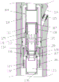
FIG. 1 is an initial schematic view of a reamer for use in oil drilling in accordance with an embodiment of the present invention;
FIG. 2 is an enlarged view of section A of FIG. 1;
FIG. 3 is an enlarged view of section B of FIG. 1;
FIG. 4 is an enlarged view of section C of FIG. 1;
FIG. 5 is a schematic illustration of a reamer for oil drilling after a shot has been placed in an embodiment of the present invention;
FIG. 6 is an enlarged view of section D of FIG. 5;
FIG. 7 is an enlarged view of section E of FIG. 5;
FIG. 8 is an enlarged view of section F of FIG. 5;
FIG. 9 is a schematic illustration of a reamer for use in oil drilling after introduction of a shut-off ball in an embodiment of the present invention;
FIG. 10 is an enlarged view of section G of FIG. 9;
FIG. 11 is an enlarged view of section H of FIG. 9;
fig. 12 is an enlarged view of section I in fig. 9.
Detailed Description
The technical solutions in the embodiments of the present invention will be described in detail below with reference to the drawings in the embodiments of the present invention, and it is obvious that the described embodiments are only a part of the embodiments of the present invention, and not all embodiments. All other embodiments, which can be obtained by a person skilled in the art without any inventive step based on the embodiments of the present invention, are within the scope of the present invention.
In the description of the present invention, it should be noted that the terms "center", "upper", "lower", "left", "right", "vertical", "horizontal", "inner", "outer", etc., indicate orientations or positional relationships based on the orientations or positional relationships shown in the drawings, and are only for convenience of description and simplicity of description, but do not indicate or imply that the device or element being referred to must have a particular orientation, be constructed and operated in a particular orientation, and thus, should not be construed as limiting the present invention. Furthermore, the terms "first," "second," and "third" are used for descriptive purposes only and are not to be construed as indicating or implying relative importance.
In the description of the present invention, it should be noted that, unless otherwise explicitly specified or limited, the terms "mounted," "connected," and "connected" are to be construed broadly, e.g., as meaning either a fixed connection, a removable connection, or an integral connection; can be mechanically or electrically connected; they may be connected directly or indirectly through intervening media, or they may be interconnected between two elements. The specific meanings of the above terms in the present invention can be understood in specific cases to those skilled in the art.
Referring to FIGS. 1-12, a reamer 100 for use in oil drilling is comprised of 3 components:
the petroleum drilling reaming structure mainly extends out the blades to realize reaming operation;
the oil drilling reaming hole diversion structure mainly realizes diversion operation, can realize reverse flow of fluid after diversion, and pushes a piston to be flushed up to extend out of a blade;
the oil drilling wing is retracted by a flow-changing structure, the changed flow is changed again, the reverse flow is closed, and the extended blade which pushes the piston to move upwards is retracted again.
The oil drilling reaming diversion structure comprises a cylindrical body 101 coaxially connected to the top of a drill rod, a first through cavity 102 is formed in the axis of the cylindrical body 101, a piston cylinder 105 and a mandrel seat 106 are coaxially and sequentially fixed in the first through cavity 102 from top to bottom, a second through cavity 118 and a third through cavity 133 are respectively formed in the axes of the piston cylinder 105 and the mandrel seat 106, the bottom of the outer wall of the piston cylinder 105 is hermetically fixed on the inner wall of the first through cavity 102, a backflow cavity 111 is formed between the outer wall of the piston cylinder 105 and the inner wall of the cylindrical body 101, a backflow hole 112 communicated with the backflow cavity 111 is formed in the inner wall of the second through cavity 118, a plurality of first through holes 127 axially parallel to the mandrel seat 106 are formed in the outer side of the third through cavity 133, a side flow cavity 128 communicated with the first through hole 127 is formed in the bottom of the second through cavity 118, an opening piston 109 attached to the inner walls of the second through cavity 118 and the third through cavity 133 is further included, the opening piston 109 is fixed, a fourth through cavity 134 is formed at the axle center of the opening piston 109, an opening ball 135 is closely carried in the fourth through cavity 134,
before the opening ball 135 is not thrown, the piston 109 is opened to shield the return hole 112 and the side flow cavity 128;
when the opening ball 135 is dropped, the opening ball 135 enters the fourth through cavity 134 from the first through cavity 102, the opening ball 135 drives the opening piston 109 to move down and break the shear pin 107, and the second through cavity 118 is communicated with the backflow hole 112 and the side flow cavity 128.
In this technical scheme, during initial condition, fluid from first logical chamber bottom downward flow, flow to the drilling rod after leading to chamber and third logical chamber in proper order, open the ball and fall the back, the shear pin 107 fracture of downside, it is whole to move down to open the piston, because open the ball and sheltered from the logical chamber in middle part, fluid partly can continue the downflow through first through-hole, another part can be through backflow hole 112 towards backflow chamber 111 to promote the piston 110 and shift up, specifically open the wing of a knife action and can continue to state below.
Further, the bottom of the third through-cavity 133 is inwardly protruded to form an annular boss 136 supporting the opening piston 109.
In the technical scheme, the device is used for supporting and opening the piston and preventing the piston from falling to the drill rod.
Further, the opening piston 109 is fixedly installed at the bushing 137, the bushing 137 is fixedly installed at the coupling 138, the coupling 138 is fixed to the mandrel base 106 by the shear pin 107, the inner diameter of the bushing 137 is gradually reduced from the top to the bottom, and the opening ball 135 acts on the bushing 137.
In the technical scheme, the bushing bears the falling force of the opening ball, so that the damage of the opening piston can be prevented, and the reliability of the whole structure is improved.
Further, the piston cylinder 105 and the mandrel seat 106 are fixedly mounted in an inner cavity of the bushing 116, the bushing 116 is fixedly mounted on an inner wall of the first through cavity 102, the backflow cavity 111 is formed between the inner wall of the bushing 116 and an outer wall of the piston cylinder 105, and the bottom of the outer wall of the piston cylinder 105 is fixedly connected with the bushing 116 in a sealing manner. The bottom of the sleeve 116 is provided with a lower fixing seat 132, and the lower fixing seat 132 supports the mandrel seat 106.
Among this technical scheme, fix piston cylinder and dabber seat simultaneously on the axle sleeve, made things convenient for the installation, can install the axle sleeve again in the cylindricality body after piston cylinder and dabber seat are installed in the axle sleeve earlier, otherwise the installation is difficult.
The flow changing structure for the wing retraction of the petroleum drilling comprises a cylindrical body 101 coaxially connected to the top of a drill rod, a first through cavity 102 is formed in the axis of the cylindrical body 101, a piston cylinder 105 and a mandrel seat 106 are coaxially and sequentially fixed in the first through cavity 102 from top to bottom, a second through cavity 118 is formed in the axis of the piston cylinder 105, the bottom of the outer wall of the piston cylinder 105 is hermetically fixed on the inner wall of the first through cavity 102, a backflow cavity 111 is formed between the outer wall of the piston cylinder 105 and the inner wall of the cylindrical body 101, a backflow hole 112 communicated with the backflow cavity 111 is formed in the inner wall of the second through cavity 118, a plurality of first through holes 127 axially parallel to the mandrel seat 106 are formed in the circumferential direction in the end portion of the mandrel seat 106, a lateral flow cavity 128 communicated with the first through holes 127 is formed in the bottom of the second through cavity 118, a closing piston 108 attached to the inner wall of the second through cavity 118, the closing piston 108 is fixed to the piston, the fifth through cavity 129 snugly carries a closing ball 130,
before the shut-off ball 130 is not put in, the fifth through cavity 129 communicates with the return hole 112 and the side flow cavity 128;
when the closing ball 130 is put in, the closing ball 130 enters the fifth through cavity 129 from the first through cavity 102, the closing ball 130 drives the closing piston 108 to move downwards and break the shear pin 107, the closing piston 108 blocks the backflow hole 112, and a lateral flow hole 131 formed in the inner wall of the fifth through cavity 129 is communicated with the lateral flow cavity 128.
In the technical scheme, the backflow hole is blocked after the ball is opened and put into the backflow hole. In specific implementation, a closing ball is put in, the closing ball drives the closing piston 108 to move downwards, the upper shear pin 107 is broken, the closing piston blocks the backflow hole 112, meanwhile, a lateral flow hole 131 formed in the closing piston 108 flows into the lateral flow cavity 128, fluid continuously flows downwards through the first through hole 127, and due to the fact that no fluid exists in the backflow cavity, the blades are recovered, and specific actions are described below.
Further, the closing piston 108 is supported by the opening piston 109, and the opening piston 109 is supported by the mandrel holder 106.
In this solution, the closing piston is supported on the opening piston after falling.
Further, the piston cylinder 105 and the mandrel seat 106 are fixedly mounted in an inner cavity of the bushing 116, the bushing 116 is fixedly mounted on an inner wall of the first through cavity 102, the backflow cavity 111 is formed between the inner wall of the bushing 116 and an outer wall of the piston cylinder 105, and the bottom of the outer wall of the piston cylinder 105 is fixedly connected with the bushing 116 in a sealing manner.
Among this technical scheme, fix piston cylinder and dabber seat simultaneously on the axle sleeve, made things convenient for the installation, can install the axle sleeve again in the cylindricality body after piston cylinder and dabber seat are installed in the axle sleeve earlier, otherwise the installation is difficult. The bottom of the sleeve 116 is provided with a lower fixing seat 132, and the lower fixing seat 132 supports the mandrel seat 106.
Further, the bottom inner diameter of the fifth through cavity 129 is gradually reduced.
In the technical scheme, the inner diameter of the closing ball is gradually reduced to prevent the closing ball from being incapable of driving the closing piston to move downwards.
The oil drilling reaming structure comprises a cylindrical body 101 coaxially connected to the top of a drill rod, a first through cavity 102 is formed in the axis of the cylindrical body 101, a central pipe 103 and a piston cylinder 105 are coaxially and fixedly installed in the first through cavity 102 from top to bottom in sequence, a sixth through cavity 117 and a second through cavity 118 are formed in the axes of the central pipe 103 and the piston cylinder 105 respectively, a push piston 110 is sleeved outside the central pipe 103, the top of the push piston 110 is hermetically connected to the central pipe 103, the bottom of the push piston 110 extends to the piston cylinder 105, a backflow cavity 111 is formed between the inner wall of the push piston 110 and the outer wall of the piston cylinder 105, the oil drilling reaming structure further comprises a plurality of blades 113 uniformly installed outside the central pipe 103 along the circumferential direction, the bottom of the blades 113 is supported on the push piston 110, a chute 119 extending upwards towards the outer side of the central pipe 103 is,
when fluid enters the return cavity 111, the pushing piston 110 is pushed to move upwards, and the blades 113 are driven to extend out along the sliding groove 119, so that hole expansion is realized.
In the technical scheme, the extension of the blade is mainly realized, when fluid impacts in the backflow cavity, the piston is pushed to move upwards, and the blade is pushed to extend upwards and outwards due to the fact that the blade is connected with the cylindrical body in a sliding mode through the sliding groove, so that the reaming action is realized.
Further, a push ring 120 is disposed between the blades 113 and the push piston 110, and the push ring 120 is fixed by a clamping seat 121.
In the technical scheme, the pushing ring is indirectly connected, so that the problems of blocking and the like are prevented.
Furthermore, the bottom of the outer side of the piston cylinder 105 is hermetically fixed on the inner wall of the first through cavity 102, and the inner wall of the second through cavity 118 is formed with a return hole 112 communicated with the return cavity 111. An opening piston 109 and a closing piston 108 are arranged in the piston cylinder 105 in a fit mode, and when the opening piston 109 moves downwards, the return hole 112 is communicated with the second through cavity 118; when the closing piston 108 moves down, the closing piston 108 blocks the return hole 112. A lower mandrel 104 is arranged between the piston cylinder 105 and the central tube 103, and a return cavity 111 is formed between the outer wall of the lower mandrel 104 and the inner wall of the pushing piston 110.
In the technical scheme, the piston is firstly opened to move downwards, so that fluid impacts in the backflow cavity; and then the piston is closed to block the backflow hole, so that no fluid impacts exist in the backflow cavity, namely the piston is pushed to move upwards and reset respectively.
Further, a stop ring 122 is arranged at the top of the blade 113, a compression spring 123 is arranged at the top of the stop ring 122, and the stop ring 122 and the compression spring 123 are simultaneously sleeved outside the central tube 103.
In this technical scheme, compression spring is used for will promoting the piston and reset, pushes down the wing of a knife promptly after the reaming is accomplished, withdraws to in the spout.
Further, a spring protection tube 124 is disposed outside the compression spring 123, and the spring protection tube 124 is mounted to the cylindrical body 101.
In the technical scheme, the protection device is used for protecting the compression spring.
Further, the top of the spring protection tube 124 is connected to the upper fixing seat 125 through a screw thread, the upper fixing seat 125 is fixed to the cylindrical body 101, and an adjusting gap 126 is formed between the bottom of the spring protection tube 124 and the stop ring 122.
In the technical scheme, the distance from the spring protection tube to the retaining ring can be adjusted through the threads, namely, the maximum extension length of the blade is that the retaining ring is attached to the spring protection tube, when the spring protection tube is in threaded connection and moves downwards, the extension of the blade is reduced, when the spring protection tube moves upwards, the blade can extend convexly a plurality of points, and the extension of the blade is adjusted.
Furthermore, a central tube 103, a lower mandrel 104, a piston cylinder 105 and a mandrel base 106 are coaxially and hermetically connected in sequence from top to bottom in the first through cavity 102, and a closing piston 108 and an opening piston 109 are coaxially and fixedly attached in sequence from top to bottom in the piston cylinder 105 through a shear pin 107.
In this solution, the closing piston and the opening piston are fixed in the piston cylinder by shear pins 107 at the same time.
Furthermore, a water hole 114 is formed on one side of the cylindrical body 101, the water hole 114 extends to the action position of the blade 113, and the water hole 114 is communicated with the backflow cavity 111.
In the technical scheme, the water hole has the function of flushing water and cooling when the cutter blade is reamed, so that the cutter blade is protected.
Further, when the piston 109 is opened and moves downwards, the water hole 114 is communicated with the return cavity 111; when the closing piston 108 moves downwards, the pushing piston 110 shields the water hole 114. A sleeve 115 is disposed inside the port 114.
In the technical scheme, the fluid in the water hole comes from the reflux cavity, and the structure is compact and reasonable.
Further, the outer wall of the return chamber 111 is formed on the inner wall of the push piston 110 and the inner wall of the bushing 116, and the inner wall of the return chamber 111 is formed on the outer wall of the lower core 104 and the outer wall of the piston cylinder 105.
It is noted that, herein, relational terms such as first and second, and the like may be used solely to distinguish one entity or action from another entity or action without necessarily requiring or implying any actual such relationship or order between such entities or actions. Also, the terms "comprises," "comprising," or any other variation thereof, are intended to cover a non-exclusive inclusion, such that a process, method, article, or apparatus that comprises a list of elements does not include only those elements but may include other elements not expressly listed or inherent to such process, method, article, or apparatus. Without further limitation, an element defined by the phrase "comprising an … …" does not exclude the presence of other identical elements in a process, method, article, or apparatus that comprises the element.
The foregoing is directed to embodiments of the present application and it is noted that numerous modifications and adaptations may be made by those skilled in the art without departing from the principles of the present application and are intended to be within the scope of the present application.
Claims (5)
Priority Applications (1)
| Application Number | Priority Date | Filing Date | Title |
|---|---|---|---|
| CN202011436148.1A CN112627770A (en) | 2020-12-10 | 2020-12-10 | Diversion structure for petroleum drilling and reaming eyes |
Applications Claiming Priority (1)
| Application Number | Priority Date | Filing Date | Title |
|---|---|---|---|
| CN202011436148.1A CN112627770A (en) | 2020-12-10 | 2020-12-10 | Diversion structure for petroleum drilling and reaming eyes |
Publications (1)
| Publication Number | Publication Date |
|---|---|
| CN112627770A true CN112627770A (en) | 2021-04-09 |
Family
ID=75309635
Family Applications (1)
| Application Number | Title | Priority Date | Filing Date |
|---|---|---|---|
| CN202011436148.1A Pending CN112627770A (en) | 2020-12-10 | 2020-12-10 | Diversion structure for petroleum drilling and reaming eyes |
Country Status (1)
| Country | Link |
|---|---|
| CN (1) | CN112627770A (en) |
Cited By (1)
| Publication number | Priority date | Publication date | Assignee | Title |
|---|---|---|---|---|
| CN112593895A (en) * | 2020-12-10 | 2021-04-02 | 苏州安能捷工具有限公司 | Oil drilling wing is received and is used structure of changing flow |
Citations (5)
| Publication number | Priority date | Publication date | Assignee | Title |
|---|---|---|---|---|
| US20130175095A1 (en) * | 2012-01-06 | 2013-07-11 | Smith International, Inc. | Pressure activated flow switch for a downhole tool |
| CN204386474U (en) * | 2015-01-07 | 2015-06-10 | 成都晋林石油机械有限责任公司 | Drill-following reamer |
| CN112593857A (en) * | 2020-12-10 | 2021-04-02 | 苏州安能捷工具有限公司 | Reamer for petroleum drilling |
| CN214221147U (en) * | 2020-12-10 | 2021-09-17 | 苏州安能捷工具有限公司 | Diversion structure for petroleum drilling and reaming eyes |
| CN214221148U (en) * | 2020-12-10 | 2021-09-17 | 苏州安能捷工具有限公司 | Oil drilling wing is received and is used structure of changing flow |
-
2020
- 2020-12-10 CN CN202011436148.1A patent/CN112627770A/en active Pending
Patent Citations (5)
| Publication number | Priority date | Publication date | Assignee | Title |
|---|---|---|---|---|
| US20130175095A1 (en) * | 2012-01-06 | 2013-07-11 | Smith International, Inc. | Pressure activated flow switch for a downhole tool |
| CN204386474U (en) * | 2015-01-07 | 2015-06-10 | 成都晋林石油机械有限责任公司 | Drill-following reamer |
| CN112593857A (en) * | 2020-12-10 | 2021-04-02 | 苏州安能捷工具有限公司 | Reamer for petroleum drilling |
| CN214221147U (en) * | 2020-12-10 | 2021-09-17 | 苏州安能捷工具有限公司 | Diversion structure for petroleum drilling and reaming eyes |
| CN214221148U (en) * | 2020-12-10 | 2021-09-17 | 苏州安能捷工具有限公司 | Oil drilling wing is received and is used structure of changing flow |
Non-Patent Citations (1)
| Title |
|---|
| 石油圈: "全排量、可伸缩Rhino XS2堪称扩眼神器", pages 1, Retrieved from the Internet <URL:https://mp.weixin.qq.com/s/2w5e6Qw7jCNA1SFidoHTwQ> * |
Cited By (1)
| Publication number | Priority date | Publication date | Assignee | Title |
|---|---|---|---|---|
| CN112593895A (en) * | 2020-12-10 | 2021-04-02 | 苏州安能捷工具有限公司 | Oil drilling wing is received and is used structure of changing flow |
Similar Documents
| Publication | Publication Date | Title |
|---|---|---|
| US4660657A (en) | Underreamer | |
| US10202814B2 (en) | Downhole tool with expandable stabilizer and underreamer | |
| RU2303689C2 (en) | Well drill bit | |
| CN102654024B (en) | Hydraulic chambering device for drilling | |
| RU2418147C1 (en) | Calibrating device of extension-type well shaft | |
| EP0301890A2 (en) | Hydraulic operated reamer | |
| US10006272B2 (en) | Actuation mechanisms for downhole assemblies and related downhole assemblies and methods | |
| CN103210176A (en) | Remote control device for downhole equipment, components for such equipment, remote status indicating device for such equipment, and related methods | |
| CN214221148U (en) | Oil drilling wing is received and is used structure of changing flow | |
| CN214273515U (en) | Reaming structure for petroleum drilling | |
| CN112593857A (en) | Reamer for petroleum drilling | |
| NO346877B1 (en) | Expandable expansion drills and methods of using expandable expansion drills | |
| US2708103A (en) | Combination drill and core bit | |
| CN214221147U (en) | Diversion structure for petroleum drilling and reaming eyes | |
| WO2014165894A1 (en) | Improved core drilling system and apparatus therefor | |
| CN214944007U (en) | Reamer for petroleum drilling | |
| CN112627770A (en) | Diversion structure for petroleum drilling and reaming eyes | |
| CN109826578B (en) | Safety type natural gas hydrate rotary pressure maintaining coring device | |
| RU2318975C1 (en) | Extendable well reamer | |
| CN116291215B (en) | Self-locking reaming-while-drilling device and application thereof | |
| CN112593895A (en) | Oil drilling wing is received and is used structure of changing flow | |
| CN112593856A (en) | Reaming structure for petroleum drilling | |
| CN214273516U (en) | Novel oil drilling reaming structure | |
| CN113027381B (en) | Novel oil drilling reaming is with changing structure that flows | |
| CN114526012B (en) | A hole expansion device while drilling and its use method |
Legal Events
| Date | Code | Title | Description |
|---|---|---|---|
| PB01 | Publication | ||
| PB01 | Publication | ||
| SE01 | Entry into force of request for substantive examination | ||
| SE01 | Entry into force of request for substantive examination | ||
| RJ01 | Rejection of invention patent application after publication | ||
| RJ01 | Rejection of invention patent application after publication |
Application publication date: 20210409 |