Deformed steel bar casting furnace
Technical Field
The invention relates to the technical field of deformed steel bar production equipment, and particularly discloses a deformed steel bar casting furnace.
Background
Deformed steel bar is a surface ribbed bar, also known as ribbed bar, which usually has 2 longitudinal ribs and transverse ribs distributed uniformly along its length. At present, the deformed steel bars on the market are all produced by small rolling mills, and when the deformed steel bars are arranged, billets are cast by a casting furnace firstly and then are heated and enter a hot rolling mill for rolling, but the two processes of the small rolling mills are separately carried out at present, so that the production efficiency is influenced, and the cost is increased.
The utility model is CN201910051155.0 discloses a deformed steel bar casting furnace, which comprises a base, the hot rolling case, cooler bin and cutting box, the top of base is equipped with branch, branch is connected with the casting furnace through the pivot, there is the heating telescoping cylinder top one side of casting furnace through the bolt fastening, there is the extension board in one side welding of base, the inside of extension board is equipped with the crystallizer, the top of crystallizer is equipped with the funnel, the bottom of crystallizer is connected with the continuous casting platform, this deformed steel bar casting furnace puts in place one step from the casting to the hot rolling shaping of steel billet, make the steel billet need not to cool off and transport, directly lead in the hot rolling shaping in the hot rolling case, and lead in the deformed steel bar after the hot rolling into the cooler bin and cool off, lead in the cutting box and cut, the effective manufacturing cost who reduces the deformed steel bar, the suitability; the deformed steel bar casting furnace still has defects in the actual use process. Firstly, the deformed steel bar casting furnace is arranged on the upper surface of the base, the height of the base is above the horizontal position, the billet raw material is heavy, the steps in the billet feeding process are complex, and the investment of auxiliary material additives in the deformed steel bar casting process is inconvenient. Secondly, this casting furnace makes whole casting furnace slope through the extension of falling the material telescoping cylinder at the material in-process of falling, thereby realize the material process of falling, but its material telescoping cylinder that falls extends to the longest and also can't incline whole casting furnace to the level, consequently the thick liquid in its casting furnace can't all pour out, some raw materialss of even surplus in the in-process of production screw-thread steel at every turn are in the casting furnace, it has not only caused the waste of raw materials, and when the casting furnace does not use, its thick liquid can form one deck dirt layer on the inner wall of casting furnace, lead to the inconvenient joining of follow-up billet raw materials. Therefore, in order to overcome the above disadvantages of the conventional deformed steel bar casting furnace, it is an object of the present invention to provide a deformed steel bar casting furnace that can simultaneously solve a series of problems that the billet raw material is inconvenient to feed and the slurry cannot be completely poured out during the material guiding.
Disclosure of Invention
The invention aims to solve the defects of the conventional deformed steel bar casting furnace, and designs a deformed steel bar casting furnace which can simultaneously solve a series of problems that the billet raw material is inconvenient to feed and the slurry cannot be completely poured out during material guiding.
The invention is realized by the following technical scheme:
a deformed steel bar casting furnace comprises a base, a casting furnace body and a feeding device, wherein a furnace body placing table is arranged at the upper right end of the base, a furnace body mounting frame is fixedly connected onto the furnace body placing table, the furnace body mounting frame comprises a front side plate, a rear side plate and an upper top plate, a semicircular clamping groove is formed in the upper top plate, rotating holes are formed in the lower ends of the front side plate and the rear side plate, the rotating holes in the two side plates are symmetrically arranged in the front and rear direction, and the outer end of each rotating hole is connected with a bearing;
wherein the casting furnace body comprises a lower heating furnace body and an upper hemispherical furnace cover, the rear ends of the lower heating furnace body and the upper hemispherical furnace cover are connected with a rotating hinge, a first telescopic device is arranged on the outer surface of the lower heating furnace body below the rotating hinge, the upper end of the first telescopic device is movably connected with the upper hemispherical furnace cover, a heat-insulating layer is arranged on the outer surface of a cylindrical section of the lower heating furnace body, an inner heat-conducting layer is arranged inside the heat-insulating layer, a spiral line type mounting groove is formed between the heat-insulating layer and the inner heat-conducting layer, a high-frequency heating coil is arranged in the spiral line type mounting groove, a plurality of liquid pouring holes are formed in the right side surface of the upper end of the lower heating furnace body, liquid pouring nozzles are arranged on the lower heating furnace body outside the liquid pouring holes, the upper end of the lower heating furnace body is clamped in the semicircular clamping groove, and convex shafts are fixedly connected with the front side and the rear side surfaces of the lower end of the lower heating furnace body below the semicircular clamping groove, the outer ends of the two protruding shafts extending out of the corresponding rotating holes and the bearings are connected with gears, guide rail plates are fixedly arranged on the furnace body placing table which is positioned right below the two gears, the guide rail plates are transversely and horizontally arranged, limiting sliding grooves are formed in the upper surfaces of the two guide rail plates, a second telescopic device is fixedly connected to a base which is positioned above the furnace body placing table, the end part of an output shaft of the second telescopic device is connected with a vertical bar, the right side surface of the vertical bar is connected with a rack, and the rack is transversely and horizontally arranged and meshed with the gears;
the feeding device comprises a receiving hopper, an auxiliary material adding feeding device and a receiving hopper moving frame, the receiving hopper moving frame comprises a rectangular frame and four stand columns, roller sliding grooves are formed in the front and rear inner side surfaces of the rectangular frame, the upper ends of the four stand columns are connected with the lower surface of the rectangular frame, the lower ends of the stand columns are fixedly connected with the upper surface of the base, the receiving hopper is arranged in the rectangular frame, the front and rear side surfaces of the receiving hopper are connected with convex blocks, the outer side surfaces of the convex blocks are rotatably connected with a plurality of rollers, the rollers are arranged in the corresponding roller sliding grooves, a transverse plate is connected between the two stand columns on the left side, a third telescopic device is fixedly connected onto the transverse plate, the right end of the third telescopic device is fixedly connected with the left side surface of the receiving hopper, and the receiving hopper is positioned right above the casting furnace body when moving to the rightmost end along the rectangular frame, the auxiliary material adding and feeding device is arranged on the left side of the upper end of the receiving hopper;
the right flank of base is provided with the flange, fixedly connected with funnel on the flange is located be provided with the crystallizer on the base of funnel below, be located the right side of base has set gradually continuous casting platform, hot rolling case, cooler bin and cutting box.
As a further arrangement of the above scheme, the auxiliary material adding and feeding device comprises a storage hopper, the lower end of the storage hopper is connected with a spiral feeding barrel, a servo motor is arranged on the left side surface of the spiral feeding barrel, the end part of a rotating shaft of the servo motor, which extends into the spiral feeding barrel, is connected with a spiral feeding blade, the lower left end of the spiral feeding barrel is connected with a discharging pipe, and the end part of the discharging pipe faces the receiving hopper.
As a further arrangement of the scheme, a vertical baffle is arranged at the left end of the upper surface of the receiving hopper, the blanking pipe penetrates through the vertical baffle and is arranged right opposite to the receiving hopper, a supporting plate extends leftwards from the lower end of the vertical baffle, a cushion block is connected to the upper surface of the supporting plate, and the spiral feeding barrel is fixedly arranged on the upper surface of the cushion block.
As a further provision of the above solution, the heat insulation layer is made of a ceramic material.
As a further arrangement of the scheme, the diameter of the pouring liquid hole is 8-20 mm.
According to the scheme, the front side and the rear side of the lower surface of the right end of the rectangular frame are both connected with the L-shaped reinforcing connecting rods, and the lower ends of the L-shaped reinforcing connecting rods are fixedly connected with the upper surface of the furnace body placing table.
As a further arrangement of the scheme, at least two rollers are arranged on the outer side surface of the bump.
As a further arrangement of the scheme, the receiving hopper is in a shape of a reversed frustum, and the lower end of the receiving hopper is connected with a discharge channel.
As a further arrangement of the scheme, feeding rails are arranged among the continuous casting table, the hot rolling box, the cooling box and the cutting box.
As a further configuration of the above scheme, the first telescopic device, the second telescopic device and the third telescopic device are one of a cylinder and a hydraulic telescopic cylinder.
Has the advantages that:
1. the deformed steel bar casting furnace disclosed by the invention has the advantages that in the feeding process, after the upper hemispherical furnace cover is opened from the lower heating furnace body by shortening the first telescopic device, the third telescopic device is started to push the receiving hopper to the leftmost end of the receiving hopper moving frame, at the moment, the receiving hopper is positioned right below the upper end opening of the lower heating furnace body, a steel billet is sucked up by the electromagnetic chuck and then is hung above the receiving hopper, the electromagnetic chuck is disconnected, the steel billet raw material can fall into the lower heating furnace body along the receiving hopper, the feeding is convenient in the whole process, and the electromagnetic chuck can be prevented from being damaged due to the fact that the electromagnetic chuck is positioned above the heating furnace body; the deformed steel bar casting furnace disclosed by the invention is convenient and quick to feed, novel in overall structural design and strong in practicability.
2. In the process of pouring slurry for casting, the rack moves leftwards through the shortening of the third telescopic device, then the whole casting furnace body can incline at a certain angle to realize material pouring through the meshing action between the rack and the gear, and the casting furnace body can rotate and incline to be horizontal, so that molten liquid in the casting furnace body can be completely poured, the defect that raw materials are easily wasted in the existing casting furnace can be overcome, and the production cost of an enterprise is reduced to a certain extent; in addition, the arrangement of the pouring liquid hole and the pouring liquid nozzle can filter the molten liquid, so that the billet raw material which is not completely molten is prevented from being introduced into the next working procedure, and the quality of the prepared deformed steel bar is effectively ensured.
3. According to the invention, the auxiliary additive in the storage hopper can be quantitatively fed into the receiving hopper by controlling the rotation of the servo motor through the arranged auxiliary material feeding device, and then enters the casting furnace body along the receiving hopper, so that the feeding of the whole auxiliary additive is convenient, the quantitative control can be realized, and the chemical and physical properties of the prepared deformed steel bar are effectively ensured.
Drawings
In order to more clearly illustrate the technical solutions of the embodiments of the present invention, the drawings used in the description of the embodiments will be briefly introduced below, and it is obvious that the drawings in the following description are only some embodiments of the present invention, and it is obvious for those skilled in the art that other drawings can be obtained according to the drawings without creative efforts.
FIG. 1 is a schematic view of a first angular perspective structure of the present invention;
FIG. 2 is a schematic view of a second angular perspective structure according to the present invention;
FIG. 3 is a schematic perspective view of a furnace body mounting frame according to the present invention;
FIG. 4 is a schematic perspective view of a casting furnace body according to the present invention;
FIG. 5 is an internal cross-sectional view of the lower furnace body of the present invention;
FIG. 6 is a greatly enlarged cross-sectional view taken at A in FIG. 1 in accordance with the present invention;
FIG. 7 is a schematic perspective view of a second retractor, a rack, and a rail plate according to the present invention;
FIG. 8 is a schematic perspective view of the receiving hopper moving frame according to the present invention;
FIG. 9 is a schematic perspective view of a receiving hopper and an auxiliary material feeding device according to the present invention;
fig. 10 is a schematic view of the internal plane structure of the auxiliary material feeding device of the present invention.
Wherein, 1-base, 101-furnace body placing table, 102-furnace body mounting rack, 1021-side plate, 1022-upper top plate, 1023-semicircular clamping groove, 1024-rotating hole, 1025-bearing, 103-guide rail plate, 1031-limit sliding groove, 104-convex plate, 2-casting furnace body, 201-lower heating furnace body, 2011-thermal insulating layer, 2012-inner heat conducting layer, 2013-spiral type mounting groove, 2014-pouring liquid hole, 2015-pouring liquid nozzle, 202-upper hemispherical furnace cover, 203-rotating hinge, 204-first telescopic device, 205-convex shaft, 206-gear, 207-second telescopic device, 208-vertical bar, 209-rack, 3-feeding device, 301-receiving hopper, 302-receiving hopper moving rack, 3021-rectangular frame, 3022-upright column, 3023-roller chute, 3024-transverse plate, 303-auxiliary material adding and feeding device, 3031-storage hopper, 3032-spiral feeding barrel, 3033-servo motor, 3034-spiral feeding blade, 3035-discharging pipe, 304-vertical baffle, 305-supporting plate, 306-cushion block, 307-discharging channel, 308-third telescopic device and 4-funnel.
Detailed Description
In order to make the technical solutions better understood by those skilled in the art, the technical solutions in the embodiments of the present application will be clearly and completely described below with reference to the drawings in the embodiments of the present application, and it is obvious that the described embodiments are only partial embodiments of the present application, but not all embodiments. All other embodiments, which can be derived by a person skilled in the art from the embodiments given herein without making any creative effort, shall fall within the protection scope of the present application.
It should be noted that the terms "first," "second," and the like in the description and claims of this application and in the drawings described above are used for distinguishing between similar elements and not necessarily for describing a particular sequential or chronological order. It should be understood that the data so used may be interchanged under appropriate circumstances such that embodiments of the application described herein may be used. Furthermore, the terms "comprises," "comprising," and any other variation thereof, are intended to cover a non-exclusive inclusion, such that a process, method, system, article, or apparatus that comprises a list of steps or elements is not necessarily limited to those steps or elements expressly listed, but may include other steps or elements not expressly listed or inherent to such process, method, article, or apparatus.
It should be noted that the embodiments and features of the embodiments in the present application may be combined with each other without conflict. The present application will be described in detail with reference to the accompanying drawings 1 to 10, in conjunction with the embodiments.
Example 1
Embodiment 1 describes a deformed steel bar casting furnace, and referring to fig. 1 and fig. 2, the main structure of the furnace comprises a base 1, a casting furnace body 2 and a feeding device 3. The furnace body is seted up at the upper right end of base 1 and is placed platform 101 to fixedly connected with furnace body mounting bracket 102 on platform 101 is placed to the furnace body, specifically furnace body mounting bracket 102 can refer to fig. 3, it includes two curb plate 1021 around and last roof 1022, has seted up semi-circular draw-in groove 1023 on the roof 1022, and rotation hole 1024 has all been seted up to the lower extreme of two curb plate 1021 around, and the symmetry sets up around rotation hole 1024 on two curb plates 1021, and is connected with bearing 1025 in every outer end of rotating hole 1024.
Referring to fig. 4 and 5, the casting furnace body 2 includes a lower heating furnace body 201 and an upper hemispherical furnace cover 202, a rotating hinge 203 is connected to rear ends of the lower heating furnace body 201 and the upper hemispherical furnace cover 202, a first expansion device 204 is disposed on an outer surface of the lower heating furnace body 201 below the rotating hinge 203, an upper end of the first expansion device 204 is movably connected to the upper hemispherical furnace cover 202, and the upper hemispherical furnace cover 202 and the lower heating furnace body 201 can be closed by extending or shortening the first expansion device 204. The outer surface of the cylindrical section of the lower heating furnace body 201 in this embodiment is provided with a heat insulating layer 2011, and the heat insulating layer 2011 is made of a ceramic material. An inner heat conductive layer 2012 is provided inside the heat insulating layer 2011, a spiral mounting groove 2013 is provided between the heat insulating layer 2011 and the inner heat conductive layer 2012, and a high-frequency heating coil (not shown) is mounted in the spiral mounting groove 2013. A plurality of pouring liquid holes 2014 are formed in the right side face of the upper end of the lower heating furnace body 201, and the diameter range of the pouring liquid holes 2014 is 8-20 mm. A pouring nozzle 2015 is arranged on the lower heating furnace body 201 positioned outside the pouring liquid hole 2014. Wherein, the upper end card of lower heating furnace body 201 is in semi-circular draw-in groove 1023 to be located the equal fixedly connected with protruding axle 205 in side around the lower end of semi-circular draw-in groove 1023 lower part lower heating furnace body 201, two protruding axles 205 stretch out the outer end that corresponds rotation hole 1024 and bearing 1025 and be connected with gear 206.
Referring to fig. 6 and 7, guide rail plates 103 are fixedly arranged on the furnace body placing table 101 directly below the two gears 206, the guide rail plates 103 are horizontally arranged, and the upper surfaces of the two guide rail plates 103 are provided with limiting sliding grooves 1031. A second telescopic device 207 is fixedly connected to the base 1 above the furnace body placing table 101, a vertical bar 208 is connected to the end of an output shaft of the second telescopic device 207, a rack 209 is connected to the right side surface of the vertical bar 208, and the rack 209 is horizontally arranged in the transverse direction and meshed with the gear 206; the entire furnace body 2 can be tilted by extending or shortening the second expansion device 207.
Referring to fig. 1, 8 and 9, the loading device 3 includes a receiving hopper 301 and a receiving hopper moving frame 302. Wherein, connect hopper to remove frame 302 and include rectangular frame 3021 and four stands 3022, gyro wheel spout 3023 has been seted up to the front and back medial surface of rectangular frame 3021, the upper end and the rectangular frame 3021 lower surface of four stands 3022 are connected, the lower extreme of stand 3022 is connected with the last fixed surface of base 1, in addition, still all be connected with L type reinforcing connecting rod 3025 in the right-hand member lower surface front and back side of rectangular frame 3021, the lower extreme of L type reinforcing connecting rod 3025 is connected with the last fixed surface that the platform 101 was placed to the furnace body to play the reinforcement to rectangular frame 3021. The material receiving hopper 301 is arranged in a rectangular frame 3021, the material receiving hopper 301 is in a shape of an inverted frustum, the lower end of the material receiving hopper 301 is connected with a material discharging channel 307, the front side and the rear side of the material receiving hopper 301 are connected with lugs 3011, the outer side of each lug 3011 is rotatably connected with a plurality of rollers 3012, and when the material receiving hopper is specifically arranged, not less than two rollers 3012 are arranged on the outer side of each lug 3011. And the rollers 3012 are disposed in the corresponding roller chutes 3023. A transverse plate 3024 is connected between the two left vertical columns 3022, a third expansion device 308 is fixedly connected to the transverse plate 3024, the right end of the third expansion device 308 is fixedly connected to the left side surface of the receiving hopper 301, and the receiving hopper 301 can be pushed to move left and right in the receiving hopper moving frame 302 by the extension or contraction of the third expansion device 308. In addition, the first expansion device 204, the second expansion device 207 and the third expansion device 308 in this embodiment may be selected from a cylinder or a hydraulic expansion cylinder, and a corresponding heat insulation process is performed. The receiving hopper 301 is located right above the casting furnace body 2 when it moves to the rightmost end along the rectangular frame 3021.
Finally, referring to fig. 1, a convex plate 104 is arranged on the right side surface of the base 1, a funnel 4 is fixedly connected to the convex plate 104, a crystallizer is arranged on the base 1 below the funnel 4, a continuous casting table, a hot rolling box, a cooling box and a cutting box are sequentially arranged on the right side of the base 1, and feeding rails are arranged among the continuous casting table, the hot rolling box, the cooling box and the cutting box (the subsequent screw-thread steel related equipment is the prior art, and the detailed description and the illustration are not provided here).
Example 2
Embodiment 2 describes a deformed steel bar casting furnace modified based on embodiment 1, and referring to fig. 1 and fig. 2, the main structure of the furnace includes a base 1, a casting furnace body 2 and a feeding device 3. The furnace body is seted up at the upper right end of base 1 and is placed platform 101 to fixedly connected with furnace body mounting bracket 102 on platform 101 is placed to the furnace body, specifically furnace body mounting bracket 102 can refer to fig. 3, it includes two curb plate 1021 around and last roof 1022, has seted up semi-circular draw-in groove 1023 on the roof 1022, and rotation hole 1024 has all been seted up to the lower extreme of two curb plate 1021 around, and the symmetry sets up around rotation hole 1024 on two curb plates 1021, and is connected with bearing 1025 in every outer end of rotating hole 1024.
Referring to fig. 4 and 5, the casting furnace body 2 includes a lower heating furnace body 201 and an upper hemispherical furnace cover 202, a rotating hinge 203 is connected to rear ends of the lower heating furnace body 201 and the upper hemispherical furnace cover 202, a first expansion device 204 is disposed on an outer surface of the lower heating furnace body 201 below the rotating hinge 203, an upper end of the first expansion device 204 is movably connected to the upper hemispherical furnace cover 202, and the upper hemispherical furnace cover 202 and the lower heating furnace body 201 can be closed by extending or shortening the first expansion device 204. The outer surface of the cylindrical section of the lower heating furnace body 201 in this embodiment is provided with a heat insulating layer 2011, and the heat insulating layer 2011 is made of a ceramic material. An inner heat conductive layer 2012 is provided inside the heat insulating layer 2011, a spiral mounting groove 2013 is provided between the heat insulating layer 2011 and the inner heat conductive layer 2012, and a high-frequency heating coil (not shown) is mounted in the spiral mounting groove 2013. A plurality of pouring liquid holes 2014 are formed in the right side face of the upper end of the lower heating furnace body 201, and the diameter range of the pouring liquid holes 2014 is 8-20 mm. A pouring nozzle 2015 is arranged on the lower heating furnace body 201 positioned outside the pouring liquid hole 2014. Wherein, the upper end card of lower heating furnace body 201 is in semi-circular draw-in groove 1023 to be located the equal fixedly connected with protruding axle 205 in side around the lower end of semi-circular draw-in groove 1023 lower part lower heating furnace body 201, two protruding axles 205 stretch out the outer end that corresponds rotation hole 1024 and bearing 1025 and be connected with gear 206.
Referring to fig. 6 and 7, guide rail plates 103 are fixedly arranged on the furnace body placing table 101 directly below the two gears 206, the guide rail plates 103 are horizontally arranged, and the upper surfaces of the two guide rail plates 103 are provided with limiting sliding grooves 1031. A second telescopic device 207 is fixedly connected to the base 1 above the furnace body placing table 101, a vertical bar 208 is connected to the end of an output shaft of the second telescopic device 207, a rack 209 is connected to the right side surface of the vertical bar 208, and the rack 209 is horizontally arranged in the transverse direction and meshed with the gear 206; the entire furnace body 2 can be tilted by extending or shortening the second expansion device 207.
Referring to fig. 1, 8 and 9, the loading device 3 includes a receiving hopper 301 and a receiving hopper moving frame 302. Wherein, connect hopper to remove frame 302 and include rectangular frame 3021 and four stands 3022, gyro wheel spout 3023 has been seted up to the front and back medial surface of rectangular frame 3021, the upper end and the rectangular frame 3021 lower surface of four stands 3022 are connected, the lower extreme of stand 3022 is connected with the last fixed surface of base 1, in addition, still all be connected with L type reinforcing connecting rod 3025 in the right-hand member lower surface front and back side of rectangular frame 3021, the lower extreme of L type reinforcing connecting rod 3025 is connected with the last fixed surface that the platform 101 was placed to the furnace body to play the reinforcement to rectangular frame 3021. The material receiving hopper 301 is arranged in a rectangular frame 3021, the material receiving hopper 301 is in a shape of an inverted frustum, the lower end of the material receiving hopper 301 is connected with a material discharging channel 307, the front side and the rear side of the material receiving hopper 301 are connected with lugs 3011, the outer side of each lug 3011 is rotatably connected with a plurality of rollers 3012, and when the material receiving hopper is specifically arranged, not less than two rollers 3012 are arranged on the outer side of each lug 3011. And the rollers 3012 are disposed in the corresponding roller chutes 3023. A transverse plate 3024 is connected between the two left vertical columns 3022, a third expansion device 308 is fixedly connected to the transverse plate 3024, the right end of the third expansion device 308 is fixedly connected to the left side surface of the receiving hopper 301, and the receiving hopper 301 can be pushed to move left and right in the receiving hopper moving frame 302 by the extension or contraction of the third expansion device 308. In addition, the first expansion device 204, the second expansion device 207 and the third expansion device 308 in this embodiment may be selected from a cylinder or a hydraulic expansion cylinder, and a corresponding heat insulation process is performed. The receiving hopper 301 is located right above the casting furnace body 2 when it moves to the rightmost end along the rectangular frame 3021.
Referring to fig. 1, a convex plate 104 is arranged on the right side surface of a base 1, a funnel 4 is fixedly connected to the convex plate 104, a crystallizer is arranged on the base 1 below the funnel 4, a continuous casting table, a hot rolling box, a cooling box and a cutting box are sequentially arranged on the right side of the base 1, and feeding rails are arranged among the continuous casting table, the hot rolling box, the cooling box and the cutting box (the subsequent screw-thread steel related equipment is the prior art, and the detailed description and the illustration are not provided here).
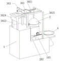
The feeding device 3 in this embodiment 2 includes a receiving hopper 301, a receiving hopper moving frame 302, and an additive package feeding device 303, which will be described in detail below with reference to fig. 9 and 10.
The auxiliary material adding and feeding device 303 comprises a storage hopper 3031, the lower end of the storage hopper 3031 is connected with a spiral feeding cylinder 3032, the left side surface of the spiral feeding cylinder 3032 is provided with a servo motor 3033, the end part of a rotating shaft of the servo motor 3033, which extends into the spiral feeding cylinder 3032, is connected with a spiral feeding blade 3034, the left lower end of the spiral feeding cylinder 3032 is connected with a discharging pipe 3035, and the end part of the discharging pipe 3035 is arranged right opposite to the receiving hopper 301. Specifically, a vertical baffle 304 is arranged at the left end of the upper surface of the receiving hopper 301, the blanking pipe 3035 passes through the vertical baffle 304 and is arranged right opposite to the receiving hopper 301, a supporting plate 305 extends leftwards from the lower end of the vertical baffle 304, a cushion block 306 is connected to the upper surface of the supporting plate 305, and the spiral feeding barrel 3032 is fixedly arranged on the upper surface of the cushion block 306.
The present invention is not limited to the above preferred embodiments, and any modifications, equivalent substitutions and improvements made within the spirit and principle of the present invention should be included in the protection scope of the present invention.