CN1126980C - Colour display with serially-connected LCD filters - Google Patents
Colour display with serially-connected LCD filters Download PDFInfo
- Publication number
- CN1126980C CN1126980C CN95118940A CN95118940A CN1126980C CN 1126980 C CN1126980 C CN 1126980C CN 95118940 A CN95118940 A CN 95118940A CN 95118940 A CN95118940 A CN 95118940A CN 1126980 C CN1126980 C CN 1126980C
- Authority
- CN
- China
- Prior art keywords
- band
- filter
- light
- lcd
- block
- Prior art date
- Legal status (The legal status is an assumption and is not a legal conclusion. Google has not performed a legal analysis and makes no representation as to the accuracy of the status listed.)
- Expired - Fee Related
Links
Images

Classifications
-
- G—PHYSICS
- G02—OPTICS
- G02F—OPTICAL DEVICES OR ARRANGEMENTS FOR THE CONTROL OF LIGHT BY MODIFICATION OF THE OPTICAL PROPERTIES OF THE MEDIA OF THE ELEMENTS INVOLVED THEREIN; NON-LINEAR OPTICS; FREQUENCY-CHANGING OF LIGHT; OPTICAL LOGIC ELEMENTS; OPTICAL ANALOGUE/DIGITAL CONVERTERS
- G02F1/00—Devices or arrangements for the control of the intensity, colour, phase, polarisation or direction of light arriving from an independent light source, e.g. switching, gating or modulating; Non-linear optics
- G02F1/01—Devices or arrangements for the control of the intensity, colour, phase, polarisation or direction of light arriving from an independent light source, e.g. switching, gating or modulating; Non-linear optics for the control of the intensity, phase, polarisation or colour
- G02F1/13—Devices or arrangements for the control of the intensity, colour, phase, polarisation or direction of light arriving from an independent light source, e.g. switching, gating or modulating; Non-linear optics for the control of the intensity, phase, polarisation or colour based on liquid crystals, e.g. single liquid crystal display cells
- G02F1/133—Constructional arrangements; Operation of liquid crystal cells; Circuit arrangements
- G02F1/1333—Constructional arrangements; Manufacturing methods
- G02F1/1335—Structural association of cells with optical devices, e.g. polarisers or reflectors
-
- H—ELECTRICITY
- H04—ELECTRIC COMMUNICATION TECHNIQUE
- H04N—PICTORIAL COMMUNICATION, e.g. TELEVISION
- H04N9/00—Details of colour television systems
- H04N9/12—Picture reproducers
- H04N9/31—Projection devices for colour picture display, e.g. using electronic spatial light modulators [ESLM]
- H04N9/3102—Projection devices for colour picture display, e.g. using electronic spatial light modulators [ESLM] using two-dimensional electronic spatial light modulators
- H04N9/3111—Projection devices for colour picture display, e.g. using electronic spatial light modulators [ESLM] using two-dimensional electronic spatial light modulators for displaying the colours sequentially, e.g. by using sequentially activated light sources
- H04N9/3114—Projection devices for colour picture display, e.g. using electronic spatial light modulators [ESLM] using two-dimensional electronic spatial light modulators for displaying the colours sequentially, e.g. by using sequentially activated light sources by using a sequential colour filter producing one colour at a time
-
- G—PHYSICS
- G02—OPTICS
- G02B—OPTICAL ELEMENTS, SYSTEMS OR APPARATUS
- G02B5/00—Optical elements other than lenses
- G02B5/30—Polarising elements
- G02B5/3016—Polarising elements involving passive liquid crystal elements
-
- G—PHYSICS
- G02—OPTICS
- G02F—OPTICAL DEVICES OR ARRANGEMENTS FOR THE CONTROL OF LIGHT BY MODIFICATION OF THE OPTICAL PROPERTIES OF THE MEDIA OF THE ELEMENTS INVOLVED THEREIN; NON-LINEAR OPTICS; FREQUENCY-CHANGING OF LIGHT; OPTICAL LOGIC ELEMENTS; OPTICAL ANALOGUE/DIGITAL CONVERTERS
- G02F1/00—Devices or arrangements for the control of the intensity, colour, phase, polarisation or direction of light arriving from an independent light source, e.g. switching, gating or modulating; Non-linear optics
- G02F1/01—Devices or arrangements for the control of the intensity, colour, phase, polarisation or direction of light arriving from an independent light source, e.g. switching, gating or modulating; Non-linear optics for the control of the intensity, phase, polarisation or colour
- G02F1/13—Devices or arrangements for the control of the intensity, colour, phase, polarisation or direction of light arriving from an independent light source, e.g. switching, gating or modulating; Non-linear optics for the control of the intensity, phase, polarisation or colour based on liquid crystals, e.g. single liquid crystal display cells
- G02F1/133—Constructional arrangements; Operation of liquid crystal cells; Circuit arrangements
- G02F1/1333—Constructional arrangements; Manufacturing methods
- G02F1/1347—Arrangement of liquid crystal layers or cells in which the final condition of one light beam is achieved by the addition of the effects of two or more layers or cells
- G02F1/13471—Arrangement of liquid crystal layers or cells in which the final condition of one light beam is achieved by the addition of the effects of two or more layers or cells in which all the liquid crystal cells or layers remain transparent, e.g. FLC, ECB, DAP, HAN, TN, STN, SBE-LC cells
- G02F1/13473—Arrangement of liquid crystal layers or cells in which the final condition of one light beam is achieved by the addition of the effects of two or more layers or cells in which all the liquid crystal cells or layers remain transparent, e.g. FLC, ECB, DAP, HAN, TN, STN, SBE-LC cells for wavelength filtering or for colour display without the use of colour mosaic filters
-
- G—PHYSICS
- G02—OPTICS
- G02F—OPTICAL DEVICES OR ARRANGEMENTS FOR THE CONTROL OF LIGHT BY MODIFICATION OF THE OPTICAL PROPERTIES OF THE MEDIA OF THE ELEMENTS INVOLVED THEREIN; NON-LINEAR OPTICS; FREQUENCY-CHANGING OF LIGHT; OPTICAL LOGIC ELEMENTS; OPTICAL ANALOGUE/DIGITAL CONVERTERS
- G02F1/00—Devices or arrangements for the control of the intensity, colour, phase, polarisation or direction of light arriving from an independent light source, e.g. switching, gating or modulating; Non-linear optics
- G02F1/01—Devices or arrangements for the control of the intensity, colour, phase, polarisation or direction of light arriving from an independent light source, e.g. switching, gating or modulating; Non-linear optics for the control of the intensity, phase, polarisation or colour
- G02F1/13—Devices or arrangements for the control of the intensity, colour, phase, polarisation or direction of light arriving from an independent light source, e.g. switching, gating or modulating; Non-linear optics for the control of the intensity, phase, polarisation or colour based on liquid crystals, e.g. single liquid crystal display cells
- G02F1/133—Constructional arrangements; Operation of liquid crystal cells; Circuit arrangements
- G02F1/1333—Constructional arrangements; Manufacturing methods
- G02F1/1335—Structural association of cells with optical devices, e.g. polarisers or reflectors
- G02F1/13363—Birefringent elements, e.g. for optical compensation
- G02F1/133638—Waveplates, i.e. plates with a retardation value of lambda/n
-
- G—PHYSICS
- G02—OPTICS
- G02F—OPTICAL DEVICES OR ARRANGEMENTS FOR THE CONTROL OF LIGHT BY MODIFICATION OF THE OPTICAL PROPERTIES OF THE MEDIA OF THE ELEMENTS INVOLVED THEREIN; NON-LINEAR OPTICS; FREQUENCY-CHANGING OF LIGHT; OPTICAL LOGIC ELEMENTS; OPTICAL ANALOGUE/DIGITAL CONVERTERS
- G02F2201/00—Constructional arrangements not provided for in groups G02F1/00 - G02F7/00
- G02F2201/34—Constructional arrangements not provided for in groups G02F1/00 - G02F7/00 reflector
- G02F2201/343—Constructional arrangements not provided for in groups G02F1/00 - G02F7/00 reflector cholesteric liquid crystal reflector
-
- G—PHYSICS
- G02—OPTICS
- G02F—OPTICAL DEVICES OR ARRANGEMENTS FOR THE CONTROL OF LIGHT BY MODIFICATION OF THE OPTICAL PROPERTIES OF THE MEDIA OF THE ELEMENTS INVOLVED THEREIN; NON-LINEAR OPTICS; FREQUENCY-CHANGING OF LIGHT; OPTICAL LOGIC ELEMENTS; OPTICAL ANALOGUE/DIGITAL CONVERTERS
- G02F2203/00—Function characteristic
- G02F2203/34—Colour display without the use of colour mosaic filters
Landscapes
- Physics & Mathematics (AREA)
- Nonlinear Science (AREA)
- Chemical & Material Sciences (AREA)
- Crystallography & Structural Chemistry (AREA)
- General Physics & Mathematics (AREA)
- Optics & Photonics (AREA)
- Mathematical Physics (AREA)
- Engineering & Computer Science (AREA)
- Multimedia (AREA)
- Signal Processing (AREA)
- Liquid Crystal (AREA)
- Devices For Indicating Variable Information By Combining Individual Elements (AREA)
Abstract
一种显示器,其彩色是通过使光透过三个串联配置的电可控滤色镜产生的,每一个滤色镜衰减三色中的一种色。该彩色滤色镜由两个胆甾醇滤光器、两个λ/4板和一个电可转换的液晶显示器组成。
A display in which colors are produced by passing light through three electrically controllable color filters arranged in series, each filter attenuating one of the three colors. The color filter consists of two cholesteric filters, two λ/4 plates and an electrically switchable liquid crystal display.
Description
技术领域technical field
本发明涉及由串联连接的电可控胆甾醇滤色镜产生彩色的一种彩色明亮显示装置。The present invention relates to a bright color display device in which colors are produced by electrically controllable cholesteric color filters connected in series.
背景技术Background technique
迄今,制造彩色液晶显示器通常采用的主要方法有三种。So far, there are three main methods commonly used in the manufacture of color liquid crystal displays.
第一种,也是最常用的方法,主要供制造直观式显示器(与投影式显示器对比)用,是以滤色镜矩阵为基础的,矩阵中的每一个象素分成三个分别配置有红、绿或蓝滤色镜的毗邻子象素。这种彩色滤色镜矩阵是以光吸收原理为基础的,透光能力小,所需要的受控象素的数目为同分辨率黑白显示器的三倍。The first, and most commonly used method, mainly for the manufacture of direct-view displays (as opposed to projection displays), is based on a matrix of color filters, with each pixel in the matrix divided into three Adjacent sub-pixels of the blue color filter. This color filter matrix is based on the principle of light absorption, and has a small light transmission ability, and the number of controlled pixels required is three times that of a black and white display with the same resolution.
第二种方法只适用于投影式显示器。投射灯来的光分成三种基色的独立光路。三条光路中,各配有液晶显示器。显示器的三幅图象由适当的光学系统对准在屏幕上。这种方法的透光能力约为第一种方法的三倍,一来是因为象素不再划分成子象素,二来这种显示器要求的分辨率比相应的黑白显示器低。这种方法的主要缺点是,光路呈非线性,这使光学系统大而重,再加上调节起来复杂,因而价钱贵。The second method only works with projection displays. The light from the projection lamp is divided into independent light paths of three primary colors. Each of the three light paths is equipped with a liquid crystal display. The three images of the display are aligned on the screen by suitable optics. The light transmission capacity of this method is about three times that of the first method, on the one hand, because the pixel is no longer divided into sub-pixels, and on the other hand, the required resolution of this display is lower than that of the corresponding black and white display. The main disadvantage of this method is that the optical path is nonlinear, which makes the optical system large and heavy, and it is complicated to adjust, so it is expensive.
第三种方法尚未公开,这种方法借助于可电转换的滤光器将来自照明灯的光依次从红色转换成绿色,显示时与同相应彩色相关的图象信息同步进行。这种方案也有上述同样的缺点,即透光率降低了六成多(在此情况下是因临时色序引起的),而且为形成序列图象所要求的速度高。A third method, not yet known, is to sequentially convert the light from the lamps from red to green by means of electrically switchable filters, which are displayed simultaneously with the image information associated with the corresponding colour. This scheme also has the same shortcoming as above, that is, the light transmittance is reduced by more than 60% (caused by the temporary color sequence in this case), and the required speed for forming sequential images is high.
发明内容Contents of the invention
本发明结合了上述各种方法的优点,而没有它们的缺点。更具体地说,本发明涉及线性光路极其简捷、透光能力高且液晶显示时无须提高速度的一种显示器。滤色镜和偏振镜都采用胆甾醇液晶滤光器,就是说,整个装置没有吸收元件,从而大大提高了其光稳定性。胆甾醇滤光器的特点是亮度和色纯度都高。本发明特别适用于投影显示系统,特别是那些装在明亮室内投影机上的投影显示系统,但是也可以用来构成直视显示器。本发明的另一个好处是,可与欧洲专利EP-A-407 830中所述的透光能力高的照明光学系统结合使用。The present invention combines the advantages of the various approaches described above without their disadvantages. More specifically, the present invention relates to a display with extremely simple linear optical path, high light transmittance and no need to increase the speed of liquid crystal display. Both color filters and polarizers are cholesteric liquid crystal filters, that is, the entire device has no absorbing elements, which greatly increases its photostability. Cholesteric filters are characterized by high brightness and color purity. The invention is particularly suitable for use in projection display systems, especially those mounted on bright room projectors, but can also be used to construct direct view displays. Another advantage of the present invention is that it can be used in combination with high light transmission illumination optics as described in European Patent EP-A-407 830.
按照本发明,提供了一种电可控的彩色明亮显示装置,该显示装置包括三个可转换带阻滤光器,其特征在于,三个可转换带阻滤光器光学上串联连接,每一个可转换带阻滤光器包含两个胆甾醇滤光器、两个λ/4板和一个带分段电极的液晶片,按照胆甾醇滤光器、λ/4板、液晶片、λ/4板、胆甾醇滤光器的顺序放置,分段电极用于对相应的液晶片进行电调制,从而转换带阻滤光器分段方式,各滤光器适于借助所述的电调制使三种不同颜色带中的一种颜色带衰减。According to the present invention, an electrically controllable color bright display device is provided, which comprises three switchable band-stop filters, characterized in that the three switchable band-stop filters are optically connected in series, each A switchable band-stop filter consists of two cholesteric filters, two λ/4 plates and a liquid crystal plate with segmented electrodes, according to the cholesteric filter, λ/4 plate, liquid crystal plate, λ/ 4 plates and cholesteric filters are placed in sequence, and the segmented electrodes are used to electrically modulate the corresponding liquid crystal sheets, thereby converting the segmented mode of the band-stop filter, and each filter is suitable for using the electrical modulation described above. One of three different color bands with attenuation.
附图说明Description of drawings
现在参照附图说明本发明的一些举例性的实施例,附图中:Some exemplary embodiments of the present invention are now described with reference to the accompanying drawings, in which:
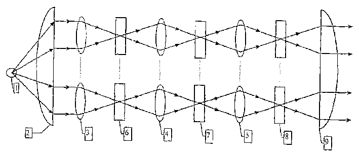
图1是本发明的投影显示系统;Fig. 1 is the projection display system of the present invention;
图2示出了可转换的带阻滤光器(SBBF)的详图;Figure 2 shows a detailed view of a switchable band-stop filter (SBBF);
图3示出了用SBBF测出的透射率。Fig. 3 shows the transmittance measured by SBBF.
具体实施方式Detailed ways
图1示出的投影系统有一个灯1,光从灯1通过聚光镜2呈平行光束投射到微型透镜矩阵3上。这种微型透镜矩阵,例如H.Hamada等人在1992年《信息显示协会(SID))文摘》第269页上作了介绍。透镜矩阵将光聚焦到可转换带阻滤光器(SBBF)6的每一个象素上。SBBF的作用(稍后将详细介绍)是根据所要求的图象信息将每一个象素的红、绿、蓝其中一个基色削弱(或反射)到不同的程度。其余的光通过微型透镜4投射到下一个SBBF7,由SBBF7将第二基色削弱到不同的程度。其余的光再次由微型透镜矩阵5投射到第三SBBF8上,第三基色在SBBF8上按图象信息加以削弱之后,通过投影透镜9最后投射到屏幕上。The projection system shown in FIG. 1 has a lamp 1 , and light from the lamp 1 is projected onto a microlens matrix 3 in the form of a parallel beam through a condenser lens 2 . Such a microlens matrix is described, for example, on page 269 of H. Hamada et al., 1992, "Society for Information Display (SID)) Digest". A matrix of lenses focuses light onto each pixel of a switchable band-stop filter (SBBF) 6 . The function of SBBF (will be introduced in detail later) is to weaken (or reflect) one of the primary colors of red, green and blue of each pixel to different degrees according to the required image information. The remaining light is projected to the next SBBF7 through the microlens 4, and the second primary color is weakened to different degrees by the SBBF7. The rest of the light is projected onto the third SBBF8 by the microlens matrix 5 again. After the third primary color is weakened according to the image information on the SBBF8, it is projected onto the screen through the projection lens 9 at last.
微型透镜是用以提高发光效率的。如果不采用这种微型透镜,也可以采用全息散射图形、菲涅耳透镜或将分级分度透镜排成矩阵。若各象素相对于各SBBF之间的间距来说大得足以避免在所要求的光束发散度下出现的不能容许的平行差,则可以不用微型透镜。若光路呈锥形(例如采用菲涅耳透镜的明亮室内的投影机的情况下就是这样),则三个LCD的大小可以取得略为不同,以便对光路的适应程度达到最佳情况。Micro lenses are used to improve luminous efficiency. If this kind of microlens is not used, holographic scattering patterns, Fresnel lenses or arranging graded and indexed lenses in a matrix can also be used. If the pixels are sufficiently large relative to the spacing between the SBBFs to avoid inadmissible parallelism at the desired beam divergence, microlenses may not be used. If the light path is tapered (as is the case with projectors in bright rooms with Fresnel lenses, for example), the three LCDs can be made slightly different sizes in order to best fit the light path.
美国专利4,726,663中介绍了类似SBBF的装置。本发明的新的特点在于,每一个象素的颜色可以切换,从而使显示器的亮度提高2倍而不致对液晶片在速率方面提出任何难以达到的要求。本发明的基本优点可以说明如下。假设在帧周期期间的入射光量由九个部分组成,每一种颜色占三个部分,再细分为三个子周期。因此可加以利用的整个光为3R+3G+3B(若限制到可利用的偏振情况,则所有讨论的方法会失去50%的光,因为这些光只以一种偏振状态工作)。若想显示出亮度高的白光,按照本发明,令三个SBBF6-8在整个周期的透射范围内工作,即透射光为(3R+3G+3B),而在采用序列滤波器的情况下,第一个1/3周期的透射光为R,第二个1/3周期的透射光为G,第三个1/3周期的透射光为B,则总的透射光为(R+G+B),即比本发明的小2/3。象素分成三色子象素时,情况也与此类似。亮白光是指,每一个象素的1/3分别为红、绿和蓝,即整个信号和前面所说的一样为(R+G+B),即比本发明的小2/3。这也适用于如欧洲专利EP-A-600 349中所述的那种反射式显示器中的胆甾醇滤波器产生的子象素。A device similar to SBBF is described in US Patent 4,726,663. The new feature of the present invention is that the color of each pixel can be switched, thereby increasing the brightness of the display by a factor of two without placing any difficult requirements on the speed of the liquid crystal panel. The basic advantages of the invention can be explained as follows. Assume that the amount of incident light during a frame period consists of nine parts, three parts for each color, subdivided into three sub-periods. The total light available is thus 3R+3G+3B (if restricted to the available polarization cases, all discussed methods lose 50% of the light since these only work with one polarization state). If want to show the high white light of brightness, according to the present invention, make three SBBF6-8 work in the transmission range of the whole cycle, promptly transmission light is (3R+3G+3B), and under the situation of adopting sequence filter, The transmitted light of the first 1/3 period is R, the transmitted light of the second 1/3 period is G, and the transmitted light of the third 1/3 period is B, then the total transmitted light is (R+G+ B), namely less than 2/3 of the present invention. The situation is similar when a pixel is divided into three-color sub-pixels. Bright white light means that 1/3 of each pixel is red, green and blue respectively, that is, the whole signal is (R+G+B) as mentioned above, which is smaller than 2/3 of the present invention. This also applies to sub-pixels produced by cholesteric filters in reflective displays of the kind described in European Patent EP-A-600 349.
图2示出了SBBF的结构。从图中可以看到可能有的三种转换状态,即,全暗(图的下半部)的全亮(上半部)。液晶片13上的其它控制电压可按需要产生中间颜色。SBBF包括胆甾醇滤光器11、λ/4板12和14、液晶片13和胆甾醇滤光器15。Figure 2 shows the structure of SBBF. From the figure it can be seen that there are three possible switching states, ie full dark (lower half of figure) and full light (upper half). Other control voltages on the liquid crystal cell 13 can produce intermediate colors as desired. The SBBF includes a
从例如M.Schadt等人在《日本应用物理杂志》(1990年,29,第10期,第1974页)上发表的文章,或从R.Maurer等人在《SID1990文摘》第110-113页上发表的文章,可以了解到胆甾醇滤光器和可能使用的单体和聚合体胆甾醇液晶的结构。胆甾醇滤光器最重要的性能是能在(所选择的反射频带的)一定波长范围内反射入射光的圆偏振分量,同时让其它光透射过去而基本上没有衰减。所反射的圆偏振光是右旋还是左旋(分别通过R或L滤光器),视乎胆甾醇液晶的旋转方向而定。同样,所选频带的位置和带宽可按周知的方式利用胆甾醇液晶的间距和双折射加以选择。From, for example, the article published by M. Schadt et al. in "Journal of Applied Physics" (1990, 29, No. 10, p. 1974), or from R. Maurer et al. in "SID1990 Digest" pp. 110-113 The structure of cholesteric filters and the possible use of monomeric and polymeric cholesteric liquid crystals can be learned from the article published above. The most important property of a cholesteric filter is the ability to reflect the circularly polarized component of incident light over a range of wavelengths (of the selected reflection band), while allowing other light to pass through with essentially no attenuation. Whether the reflected circularly polarized light is right-handed or left-handed (through R or L filters, respectively) depends on the direction of rotation of the cholesteric liquid crystal. Likewise, the location and bandwidth of the selected frequency bands can be selected in a known manner using the spacing and birefringence of cholesteric liquid crystals.
图2只示出了光在所选频带内的偏振情况,所选频带外无偏振的天然光的偏振情况没有变化。所选频带内的无偏振光10照射到胆甾醇L滤光器11。这里只让R偏振光透过,L偏振光则被反射回去,按照欧洲专利EP-A-407830所说,这可用来提高发光效率。透射的R光由λ/4板12转换成线性偏振光(“P”代表平行于垂直方向的偏振,“S”代表垂直于垂直方向的偏振)。液晶片13能将光偏振成不同程度的椭圆偏振光,刚提到的两种极限情况“P”和“S”是其特殊情况。稍后将列出可用作这种用途的多种可利用的液晶片。在液晶片13之后,光照射到另一个λ/4板14和胆甾醇R滤光器15上。Figure 2 only shows the polarization of light within the selected frequency band, and the polarization of unpolarized natural light outside the selected frequency band does not change. The
在上光路中,液晶片13使P偏振光旋转90度而成为S光。图中,这是用倾斜于垂直方向45度角的λ/2板表示的,也可以是以偏振传输方式的扭转向列(TN)型液晶片。液晶片13之后的S偏振光由λ/4板14转换成L圆偏振光,再无衰减地透过胆甾醇R滤光器15射出,该滤光器处于让光透过的状态(16)。In the upper optical path, the liquid crystal panel 13 rotates the P polarized light by 90 degrees to become S light. In the figure, this is represented by a λ/2 plate inclined at an angle of 45 degrees to the vertical direction, and it may also be a twisted nematic (TN) type liquid crystal panel in a polarization transmission mode. The S polarized light behind the liquid crystal panel 13 is converted into L circularly polarized light by the λ/4
在下面的光路中,P偏振光在通过液晶片13后保持不动。图中,这是通过双折射的一个主轴平行于偏振方向表示的。但从同向扭转(homoeotropically)取向的液晶层也可取得同样的光学效果。在液晶片13之后,光由λ/4板14转换成R圆偏振光。此光不能通过胆甾醇R滤光器15。因此两光路中下面的一个光路相当于滤光器的不导光状态。中间状态对应于灰度值或各种彩色共用坐标。In the lower light path, the P-polarized light remains motionless after passing through the liquid crystal panel 13 . In the figure, this is represented by one main axis of birefringence being parallel to the polarization direction. However, the same optical effect can also be obtained from a homoeotropically oriented liquid crystal layer. After the liquid crystal cell 13, the light is converted into R circularly polarized light by the λ/4
因此,图2所示的SBBF具有图1的滤波器6、7和8所要求的性能,即可使波长范围减小到不同的程度。Therefore, the SBBF shown in FIG. 2 has the properties required by filters 6, 7 and 8 of FIG. 1, ie, the wavelength range is reduced to different degrees.
滤光器15所反射的未透射的光一定不得从任何层面(例如液晶片13的电极层),特别是在不导光状态下,反射回去,否则会使对比度大大下降。但由于这类反射不可能完全避免,因此必须注意使此反射光偏振得不致通过滤光器15,即要受到R圆形偏振的作用。这正是λ/4板14的作用,因为λ/4板14在各接触点处可产生任何反射之前已将反射的R光再转换成线性偏振光。若例如在液晶片13处仍出现这些反射光,则这些光仍然处于线性偏振状态,且在通过λ/4板14时再次受到R偏振。若省去λ/4板14,则R光在液晶片13上反射时会被转换成L光,从而能通过滤光器15。因此,要获取高对比度,λ/4板14是个关键。这种板在例如S.Sato和M.Wada的可转换滤色装置(美国纽约1974年2月ED-21卷第二期的《电气与电子工程师协会电子设备论文集》第171-172页)中就没有设置。The non-transmitted light reflected by the
与顺次驱动相比,本发明对SBBF所透过的光的振性能方面并不提出任何要求,因为唯一重要的因素是光的强度。因此,SBBF可以用同样的胆甾醇滤光器11和15构成。导光与不导光之间的转换,取决于所选取的元件12-14的取向。本技术领域的行家都知道,液晶片13和λ/4板12、14有许多可能的取向,其性能基本上与图2实施例的相同。In contrast to sequential driving, the present invention does not place any requirements on the vibration performance of the light transmitted by the SBBF, since the only important factor is the intensity of the light. Therefore, the SBBF can be constructed with the same
胆甾醇滤光器特有的光学性能(滤出的光边缘清晰,没有吸收的纯介电效应)使显示器显示面明亮、光稳定性好,色饱和度优异。这与二向色颜料为主要材料的显示器(见欧洲专利EP-A-509 727)成了鲜明的对比,后者色饱和度较低,且由于其吸收性能,光稳定性也欠佳。The unique optical properties of the cholesteric filter (the edge of the filtered light is clear, there is no pure dielectric effect of absorption) makes the display surface bright, with good light stability and excellent color saturation. This is in stark contrast to displays based on dichroic pigments (see European Patent EP-A-509 727), which have lower color saturation and are less photostable due to their absorbing properties.
有许多液晶片适用作电光片13,这些液晶片必须能满足将给定的线性偏振(图2中的P)转换成不同程度的椭圆偏振光(视乎所加的电压而定)的要求,这里光学对比度有两个极限值,即1)偏振作用不变;和2)有90度的偏振旋转。此外,必须能用适当的方法在所要求的帧频下调制全部要求的象素(在极端情况下为含数百万象素的二维矩阵)。调制可通过直接驱动或通过多路调制(包括有效编址多路调制),或借助于有源矩阵进行。下面是这些LCD的一些实例:TN-LCD、STN-LCD、ECB-LCD、DAP-LCD、OMI-LCD、聚合物浸渍过的LCD、DHF-LCD、或其它能产生灰度值的铁电LCD(例如,电荷控制SSF-LCD、SBF-LCD或抗铁电LCD)。There are many liquid crystal cells suitable for use as the electro-optic cell 13, and these liquid crystal cells must be able to meet the requirements of converting a given linear polarization (P in Fig. 2) into different degrees of elliptically polarized light (depending on the applied voltage), There are two extremes of optical contrast here, namely 1) the polarization effect is constant; and 2) there is a polarization rotation of 90 degrees. Furthermore, it must be possible to modulate all required pixels (in the extreme case a two-dimensional matrix of millions of pixels) at the required frame rate by a suitable method. Modulation can be by direct drive or by multiplexing (including active address multiplexing), or by means of an active matrix. The following are some examples of these LCDs: TN-LCD, STN-LCD, ECB-LCD, DAP-LCD, OMI-LCD, polymer impregnated LCD, DHF-LCD, or other ferroelectric LCDs capable of producing grayscale values (eg charge controlled SSF-LCD, SBF-LCD or anti-ferroelectric LCD).
图3示出了图2 SBBF不偏振光的透射谱。胆甾醇滤光器12和14各有两个覆有聚酰亚胺的磨砂玻璃,彼此间隔8微米,两玻璃板之间有胆甾醇液晶混合料,并具有适当的双折射性和胆甾醇螺旋线的间距。从例如M.Schadt等人在1990年第29卷第10期的《日本应用物理杂志》第1974页上发表的文章可了解到这种液晶片的结构。液晶片13是常规的TN液晶片。λ/4板是市场上出售的延迟薄膜,其间距差为140纳米。所有组成部分都用光学粘结剂粘接在一起。图3示出了导光状态(片上电压为0伏)和不导光状态(10Vpp,片上有1千赫的方波)下的透射谱。可以清楚地看出,对比度良好,滤波特性曲线陡峭。Figure 3 shows the transmission spectrum of the SBBF of Figure 2 for unpolarized light. Cholesteric filters 12 and 14 each have two polyimide-coated ground glasses spaced 8 microns from each other with a cholesteric liquid crystal compound between the two glass plates, with appropriate birefringence and cholesteric helical Line spacing. The structure of such a liquid crystal cell is known, for example, from the article published by M. Schadt et al. in "Japanese Journal of Applied Physics" Vol. 29 No. 10, 1990, p. 1974. The liquid crystal panel 13 is a conventional TN liquid crystal panel. The λ/4 plate is a commercially available retardation film with a pitch difference of 140 nm. All components are bonded together with optical adhesives. Figure 3 shows the transmission spectra in the light-guiding state (0 volts on-chip) and non-light-guiding state (10 Vpp, 1 kHz square wave on the chip). It can be clearly seen that the contrast is good and the filter characteristic curve is steep.
本发明主要应用于极其小巧的显示性能高的液晶投影显示器,例如供高清晰度电视投影机(带微型透镜的那一种),或象素较大的或采用其它象素而不带微型透镜的显示器,在这些场合,本发明在亮度和彩色方面的质量有了重要的改进。在上述两种情况下,除了对现代市面出售的显示器业已提出的各项要求之外,在液晶元件方面并无其它要求。这与顺次驱动式显示器成了鲜明的对照,在这种场合,现代显示器的显示速率仍然不够快。按照本发明也可以制取直观式显示器(取消图1中的投影透镜9),但其视角范围稍微受到选择性反射依赖于角度的特性的限制。The present invention is mainly applied to extremely compact liquid crystal projection displays with high display performance, such as high-definition television projectors (the one with microlenses), or those with larger pixels or other pixels without microlenses In these applications, the present invention provides important improvements in brightness and color quality. In both cases, there are no requirements on the liquid crystal cell other than those already imposed on modern commercially available displays. This is in stark contrast to sequentially driven displays, where the display rate of modern displays is still not fast enough. Direct-view displays can also be produced according to the invention (omitting the projection lens 9 in FIG. 1), but the range of viewing angles is somewhat limited by the angle-dependent nature of the selective reflection.
Claims (8)
Applications Claiming Priority (3)
| Application Number | Priority Date | Filing Date | Title |
|---|---|---|---|
| CH340794 | 1994-11-14 | ||
| CH3407/1994 | 1994-11-14 | ||
| CH3407/94 | 1994-11-14 |
Publications (2)
| Publication Number | Publication Date |
|---|---|
| CN1151060A CN1151060A (en) | 1997-06-04 |
| CN1126980C true CN1126980C (en) | 2003-11-05 |
Family
ID=4255331
Family Applications (1)
| Application Number | Title | Priority Date | Filing Date |
|---|---|---|---|
| CN95118940A Expired - Fee Related CN1126980C (en) | 1994-11-14 | 1995-11-13 | Colour display with serially-connected LCD filters |
Country Status (6)
| Country | Link |
|---|---|
| US (1) | US5686931A (en) |
| EP (1) | EP0713126A1 (en) |
| JP (1) | JPH08234192A (en) |
| KR (1) | KR100258048B1 (en) |
| CN (1) | CN1126980C (en) |
| SG (1) | SG47360A1 (en) |
Families Citing this family (75)
| Publication number | Priority date | Publication date | Assignee | Title |
|---|---|---|---|---|
| US5822021A (en) * | 1996-05-14 | 1998-10-13 | Colorlink, Inc. | Color shutter liquid crystal display system |
| US6707516B1 (en) | 1995-05-23 | 2004-03-16 | Colorlink, Inc. | Single-panel field-sequential color display systems |
| US6183091B1 (en) * | 1995-04-07 | 2001-02-06 | Colorlink, Inc. | Color imaging systems and methods |
| US5999240A (en) * | 1995-05-23 | 1999-12-07 | Colorlink, Inc. | Optical retarder stack pair for transforming input light into polarization states having saturated color spectra |
| US6252638B1 (en) | 1995-05-23 | 2001-06-26 | Colorlink, Inc. | Color controllable illumination device, indicator lights, transmissive windows and color filters employing retarder stacks |
| US6882384B1 (en) * | 1995-05-23 | 2005-04-19 | Colorlink, Inc. | Color filters and sequencers using color selective light modulators |
| US5751384A (en) | 1995-05-23 | 1998-05-12 | The Board Of Regents Of The University Of Colorado | Color polarizers for polarizing an additive color spectrum along a first axis and it's compliment along a second axis |
| US5929946A (en) * | 1995-05-23 | 1999-07-27 | Colorlink, Inc. | Retarder stack for preconditioning light for a modulator having modulation and isotropic states of polarization |
| US6273571B1 (en) | 1995-05-23 | 2001-08-14 | Colorlink, Inc. | Display architectures using an electronically controlled optical retarder stack |
| US6417892B1 (en) | 1995-05-23 | 2002-07-09 | Colorlink, Inc. | Color filters, sequencers and displays using color selective light modulators |
| US6049367A (en) * | 1995-05-23 | 2000-04-11 | Colorlink, Inc. | Polarization manipulating device modulator with retarder stack which preconditions light for modulation and isotropic states |
| JPH10170905A (en) * | 1996-12-09 | 1998-06-26 | Alps Electric Co Ltd | Color polarization filter for reflection and reflection-type color liquid crystal display device using the filter |
| US6204901B1 (en) | 1997-07-31 | 2001-03-20 | Duke University | Liquid crystal color shutters that include reflective polarizers that pass color components of light of a first polarization and that reflect a majority of color components of light of a second polarization |
| EP1101213B1 (en) * | 1998-07-31 | 2009-05-27 | Colorlink, Inc. | Color filters, sequencers and displays using color selective light modulators |
| US6217174B1 (en) * | 1999-01-28 | 2001-04-17 | Richard M. Knox | Image projection |
| US6490017B1 (en) | 1999-01-28 | 2002-12-03 | Duke University | Separating white light into polarized, colored light |
| WO2001057587A1 (en) * | 2000-02-03 | 2001-08-09 | Rolic Ag | Colour switch |
| US7116378B1 (en) * | 2000-08-15 | 2006-10-03 | Displaytech, Inc. | Color-balanced brightness enhancement for display systems |
| JP4651791B2 (en) * | 2000-08-29 | 2011-03-16 | Nec液晶テクノロジー株式会社 | Reflective liquid crystal display device, manufacturing method thereof, and driving method thereof |
| EP1203980A1 (en) * | 2000-11-03 | 2002-05-08 | Rolic AG | Switchable color filter |
| KR100444986B1 (en) * | 2001-09-29 | 2004-08-21 | 삼성전자주식회사 | Illumination system and a projector imploying it |
| US7046221B1 (en) | 2001-10-09 | 2006-05-16 | Displaytech, Inc. | Increasing brightness in field-sequential color displays |
| EP1306717A1 (en) * | 2001-10-24 | 2003-05-02 | Rolic AG | Switchable color filter |
| GB0522968D0 (en) | 2005-11-11 | 2005-12-21 | Popovich Milan M | Holographic illumination device |
| GB0718706D0 (en) | 2007-09-25 | 2007-11-07 | Creative Physics Ltd | Method and apparatus for reducing laser speckle |
| US7845822B2 (en) * | 2006-12-29 | 2010-12-07 | Koninklijke Philips Electronics N.V. | Illumination device including a color selecting panel for recycling unwanted light |
| US11726332B2 (en) | 2009-04-27 | 2023-08-15 | Digilens Inc. | Diffractive projection apparatus |
| US9335604B2 (en) | 2013-12-11 | 2016-05-10 | Milan Momcilo Popovich | Holographic waveguide display |
| US11204540B2 (en) | 2009-10-09 | 2021-12-21 | Digilens Inc. | Diffractive waveguide providing a retinal image |
| DE102010030108B4 (en) | 2010-06-15 | 2014-12-04 | Fraunhofer-Gesellschaft zur Förderung der angewandten Forschung e.V. | Color sensor |
| JP4714301B1 (en) * | 2010-07-02 | 2011-06-29 | 日本発條株式会社 | Identification medium and identification device |
| US9274349B2 (en) | 2011-04-07 | 2016-03-01 | Digilens Inc. | Laser despeckler based on angular diversity |
| US10670876B2 (en) | 2011-08-24 | 2020-06-02 | Digilens Inc. | Waveguide laser illuminator incorporating a despeckler |
| EP2748670B1 (en) | 2011-08-24 | 2015-11-18 | Rockwell Collins, Inc. | Wearable data display |
| WO2016020630A2 (en) | 2014-08-08 | 2016-02-11 | Milan Momcilo Popovich | Waveguide laser illuminator incorporating a despeckler |
| US20150010265A1 (en) | 2012-01-06 | 2015-01-08 | Milan, Momcilo POPOVICH | Contact image sensor using switchable bragg gratings |
| EP2842003B1 (en) | 2012-04-25 | 2019-02-27 | Rockwell Collins, Inc. | Holographic wide angle display |
| US9456744B2 (en) | 2012-05-11 | 2016-10-04 | Digilens, Inc. | Apparatus for eye tracking |
| US9933684B2 (en) | 2012-11-16 | 2018-04-03 | Rockwell Collins, Inc. | Transparent waveguide display providing upper and lower fields of view having a specific light output aperture configuration |
| US10209517B2 (en) | 2013-05-20 | 2019-02-19 | Digilens, Inc. | Holographic waveguide eye tracker |
| US9727772B2 (en) | 2013-07-31 | 2017-08-08 | Digilens, Inc. | Method and apparatus for contact image sensing |
| WO2016020632A1 (en) | 2014-08-08 | 2016-02-11 | Milan Momcilo Popovich | Method for holographic mastering and replication |
| WO2016042283A1 (en) | 2014-09-19 | 2016-03-24 | Milan Momcilo Popovich | Method and apparatus for generating input images for holographic waveguide displays |
| EP3198192A1 (en) | 2014-09-26 | 2017-08-02 | Milan Momcilo Popovich | Holographic waveguide opticaltracker |
| US10437064B2 (en) | 2015-01-12 | 2019-10-08 | Digilens Inc. | Environmentally isolated waveguide display |
| EP3245551B1 (en) | 2015-01-12 | 2019-09-18 | DigiLens Inc. | Waveguide light field displays |
| CN107533137A (en) | 2015-01-20 | 2018-01-02 | 迪吉伦斯公司 | Holographical wave guide laser radar |
| US9632226B2 (en) | 2015-02-12 | 2017-04-25 | Digilens Inc. | Waveguide grating device |
| WO2016146963A1 (en) | 2015-03-16 | 2016-09-22 | Popovich, Milan, Momcilo | Waveguide device incorporating a light pipe |
| US10591756B2 (en) | 2015-03-31 | 2020-03-17 | Digilens Inc. | Method and apparatus for contact image sensing |
| WO2017060665A1 (en) | 2015-10-05 | 2017-04-13 | Milan Momcilo Popovich | Waveguide display |
| EP3398007B1 (en) | 2016-02-04 | 2024-09-11 | DigiLens, Inc. | Waveguide optical tracker |
| JP6895451B2 (en) | 2016-03-24 | 2021-06-30 | ディジレンズ インコーポレイテッド | Methods and Devices for Providing Polarized Selective Holography Waveguide Devices |
| EP3433658B1 (en) | 2016-04-11 | 2023-08-09 | DigiLens, Inc. | Holographic waveguide apparatus for structured light projection |
| EP3548939A4 (en) | 2016-12-02 | 2020-11-25 | DigiLens Inc. | WAVE GUIDE DEVICE WITH UNIFORM OUTPUT LIGHTING |
| US10545346B2 (en) | 2017-01-05 | 2020-01-28 | Digilens Inc. | Wearable heads up displays |
| CN111386495B (en) | 2017-10-16 | 2022-12-09 | 迪吉伦斯公司 | System and method for doubling the image resolution of a pixelated display |
| WO2019136476A1 (en) | 2018-01-08 | 2019-07-11 | Digilens, Inc. | Waveguide architectures and related methods of manufacturing |
| JP7456929B2 (en) | 2018-01-08 | 2024-03-27 | ディジレンズ インコーポレイテッド | Systems and methods for manufacturing waveguide cells |
| JP7404243B2 (en) | 2018-01-08 | 2023-12-25 | ディジレンズ インコーポレイテッド | Systems and methods for high-throughput recording of holographic gratings in waveguide cells |
| CN114721242B (en) | 2018-01-08 | 2025-08-15 | 迪吉伦斯公司 | Method for manufacturing optical waveguide |
| US10690851B2 (en) | 2018-03-16 | 2020-06-23 | Digilens Inc. | Holographic waveguides incorporating birefringence control and methods for their fabrication |
| US11402801B2 (en) | 2018-07-25 | 2022-08-02 | Digilens Inc. | Systems and methods for fabricating a multilayer optical structure |
| WO2020149956A1 (en) | 2019-01-14 | 2020-07-23 | Digilens Inc. | Holographic waveguide display with light control layer |
| US20200247017A1 (en) | 2019-02-05 | 2020-08-06 | Digilens Inc. | Methods for Compensating for Optical Surface Nonuniformity |
| EP3924759B1 (en) | 2019-02-15 | 2025-07-30 | Digilens Inc. | Methods and apparatuses for providing a holographic waveguide display using integrated gratings |
| US20220283377A1 (en) | 2019-02-15 | 2022-09-08 | Digilens Inc. | Wide Angle Waveguide Display |
| JP2022525165A (en) | 2019-03-12 | 2022-05-11 | ディジレンズ インコーポレイテッド | Holographic Waveguide Backlights and Related Manufacturing Methods |
| EP3980825A4 (en) | 2019-06-07 | 2023-05-03 | Digilens Inc. | WAVEGUIDES INCORPORATING TRANSPARENT AND REFLECTIVE GRATINGS AND METHODS OF MAKING THEREOF |
| JP2022543571A (en) | 2019-07-29 | 2022-10-13 | ディジレンズ インコーポレイテッド | Method and Apparatus for Multiplying Image Resolution and Field of View for Pixelated Displays |
| JP2022546413A (en) | 2019-08-29 | 2022-11-04 | ディジレンズ インコーポレイテッド | Vacuum grating and manufacturing method |
| CN110764307B (en) * | 2019-11-28 | 2022-02-15 | 京东方科技集团股份有限公司 | Liquid crystal display panel and liquid crystal display device |
| EP4252048A4 (en) | 2020-12-21 | 2024-10-16 | Digilens Inc. | EYEGLOW SUPPRESSION IN WAVEGUIDE-BASED DISPLAYS |
| WO2022150841A1 (en) | 2021-01-07 | 2022-07-14 | Digilens Inc. | Grating structures for color waveguides |
| KR20230153459A (en) | 2021-03-05 | 2023-11-06 | 디지렌즈 인코포레이티드. | Vacuum periodic structure and manufacturing method |
Citations (3)
| Publication number | Priority date | Publication date | Assignee | Title |
|---|---|---|---|---|
| US4017156A (en) * | 1974-02-28 | 1977-04-12 | Matsushita Electric Industrial Co., Ltd. | Electro-optical display device |
| EP0516479A2 (en) * | 1991-05-31 | 1992-12-02 | Sharp Kabushiki Kaisha | A projection-type liquid crystal display apparatus |
| US5325218A (en) * | 1992-12-31 | 1994-06-28 | Minnesota Mining And Manufacturing Company | Cholesteric polarizer for liquid crystal display and overhead projector |
Family Cites Families (17)
| Publication number | Priority date | Publication date | Assignee | Title |
|---|---|---|---|---|
| US4416514A (en) * | 1980-11-10 | 1983-11-22 | Polaroid Corporation | Color filter |
| EP0138454B1 (en) * | 1983-09-26 | 1994-08-31 | Tektronix, Inc. | Switchable color filter and field sequential full color display system incorporating same |
| US4867536A (en) * | 1986-02-05 | 1989-09-19 | Ford Motor Company | Color selectable liquid crystal display system |
| US4843381A (en) * | 1986-02-26 | 1989-06-27 | Ovonic Imaging Systems, Inc. | Field sequential color liquid crystal display and method |
| US4770500A (en) * | 1986-06-10 | 1988-09-13 | Kaiser Aerospace And Electronics Corporation | Method and apparatus for multi color display |
| US4726663A (en) * | 1986-11-14 | 1988-02-23 | Tektronix, Inc. | Switchable color filter with enhanced transmissivity |
| US5032007A (en) * | 1988-04-07 | 1991-07-16 | Honeywell, Inc. | Apparatus and method for an electronically controlled color filter for use in information display applications |
| US4968120A (en) * | 1988-10-28 | 1990-11-06 | International Business Machines Corp. | Multicolor liquid crystal display |
| US5050965A (en) * | 1989-09-01 | 1991-09-24 | In Focus Systems, Inc. | Color display using supertwisted nematic liquid crystal material |
| SG50550A1 (en) * | 1989-07-10 | 2002-04-16 | Rolic Ag | Polarisator |
| US5235443A (en) * | 1989-07-10 | 1993-08-10 | Hoffmann-La Roche Inc. | Polarizer device |
| US5347378A (en) * | 1991-04-04 | 1994-09-13 | Displaytech, Inc. | Fast switching color filters for frame-sequential video using ferroelectric liquid crystal color-selective filters |
| JP2829149B2 (en) * | 1991-04-10 | 1998-11-25 | シャープ株式会社 | Liquid crystal display |
| US5315418A (en) * | 1992-06-17 | 1994-05-24 | Xerox Corporation | Two path liquid crystal light valve color display with light coupling lens array disposed along the red-green light path |
| US5309365A (en) * | 1992-07-02 | 1994-05-03 | Gerber Scientific Products, Inc. | System for cutting artificial nail tips and for decorating the same or existing nails using automated cutting processes |
| JP3268858B2 (en) * | 1992-11-30 | 2002-03-25 | 三洋電機株式会社 | Liquid crystal display |
| US5751385A (en) * | 1994-06-07 | 1998-05-12 | Honeywell, Inc. | Subtractive color LCD utilizing circular notch polarizers and including a triband or broadband filter tuned light source or dichroic sheet color polarizers |
-
1995
- 1995-11-01 SG SG1995001701A patent/SG47360A1/en unknown
- 1995-11-03 EP EP95117290A patent/EP0713126A1/en not_active Ceased
- 1995-11-03 US US08/552,664 patent/US5686931A/en not_active Expired - Fee Related
- 1995-11-13 CN CN95118940A patent/CN1126980C/en not_active Expired - Fee Related
- 1995-11-14 JP JP7295535A patent/JPH08234192A/en active Pending
- 1995-11-14 KR KR1019950042150A patent/KR100258048B1/en not_active Expired - Fee Related
Patent Citations (3)
| Publication number | Priority date | Publication date | Assignee | Title |
|---|---|---|---|---|
| US4017156A (en) * | 1974-02-28 | 1977-04-12 | Matsushita Electric Industrial Co., Ltd. | Electro-optical display device |
| EP0516479A2 (en) * | 1991-05-31 | 1992-12-02 | Sharp Kabushiki Kaisha | A projection-type liquid crystal display apparatus |
| US5325218A (en) * | 1992-12-31 | 1994-06-28 | Minnesota Mining And Manufacturing Company | Cholesteric polarizer for liquid crystal display and overhead projector |
Also Published As
| Publication number | Publication date |
|---|---|
| JPH08234192A (en) | 1996-09-13 |
| US5686931A (en) | 1997-11-11 |
| CN1151060A (en) | 1997-06-04 |
| EP0713126A1 (en) | 1996-05-22 |
| KR100258048B1 (en) | 2000-06-01 |
| SG47360A1 (en) | 1998-04-17 |
| KR960019044A (en) | 1996-06-17 |
Similar Documents
| Publication | Publication Date | Title |
|---|---|---|
| CN1126980C (en) | Colour display with serially-connected LCD filters | |
| US7511787B2 (en) | Color filters and sequencers using color-selective light modulators | |
| US6667784B2 (en) | Color filters, sequencers and displays using color selective light modulators | |
| JP4608687B2 (en) | Color selective light modulator | |
| US5539547A (en) | Liquid crystal device with plural polymer network films | |
| EP2350736B1 (en) | Polarization-independent liquid crystal display devices including multiple polarization grating arrangements and related devices | |
| US6426785B2 (en) | Reflective liquid crystal display device | |
| CN1152358A (en) | Display device with diffuse display panel | |
| US20080198456A1 (en) | Laminated retarder stack | |
| JP3816467B2 (en) | Liquid crystal display | |
| JPH0297992A (en) | Projection device | |
| KR101169401B1 (en) | Vertically aligned nematic mode liquid crystal display having large tilt angles and high contrast | |
| JPH04338721A (en) | Reflection type optical modulation panel and projection type display device | |
| CN1410807A (en) | Liquid crystal display element and display device using same | |
| CN1945403A (en) | image display device | |
| CN1126981C (en) | Ferroelectric liquid crystal cell | |
| JPS63168622A (en) | Optical deflecting element | |
| JP3482737B2 (en) | Reflective liquid crystal display | |
| JP4194381B2 (en) | Optical deflection device | |
| CN1073267A (en) | Colour display device | |
| JP2003005132A (en) | Image projection device | |
| JP3534371B2 (en) | Liquid crystal display device | |
| JP2000089208A (en) | Reflective liquid crystal display | |
| JPH0588153A (en) | Liquid crystal panel and liquid crystal display device formed by using this panel | |
| Fünfschilling et al. | Video‐compatible subtractive color projection with cholesteric liquid‐crystal band‐modulation filters |
Legal Events
| Date | Code | Title | Description |
|---|---|---|---|
| C06 | Publication | ||
| PB01 | Publication | ||
| C10 | Entry into substantive examination | ||
| SE01 | Entry into force of request for substantive examination | ||
| C53 | Correction of patent of invention or patent application | ||
| CB02 | Change of applicant information |
Address after: Swiss Swiss Applicant after: Rolic AG Address before: Basel, Switzerland Applicant before: Hoffman-La Roche Ltd. |
|
| COR | Change of bibliographic data |
Free format text: CORRECT: APPLICANT; FROM: HOFFMAN-LALUOAI LTD. TO: RALEIGHCO STOCK CO., LTD. |
|
| C14 | Grant of patent or utility model | ||
| GR01 | Patent grant | ||
| C19 | Lapse of patent right due to non-payment of the annual fee | ||
| CF01 | Termination of patent right due to non-payment of annual fee |