Disclosure of Invention
The latch assembly and method of installing the latch assembly disclosed herein may simplify installation of the latch assembly while maintaining the functionality of the latch assembly.
According to a first aspect, there is disclosed a latch assembly mountable to a structure including a latch, a remote actuating unit, and a guide formed separately from the latch and the remote actuating unit, the latch and the remote actuating unit being arranged to be connected by at least one aperture formed in the structure, and wherein the guide is adapted to facilitate mounting of the latch assembly, wherein, upon mounting the assembly on the structure, the guide mounts one of the latch or the remote actuating unit.
In some forms, the guide forms a base plate of a latch or remote actuation unit. Incorporating the guide as part of the latch of the remote actuation unit simplifies mounting the latch assembly to a structure and reduces the tooling required for installation.
In some forms, the guide includes a body having at least one indicia indicator and at least one alignment indicator to facilitate forming at least one aperture in the structure. In this way, the guide may be used to easily and efficiently mark the correct position of the at least one aperture in the structure. In some forms, the body further comprises a reference axis arranged, in use, to be aligned in the direction of the structure when the guide facilitates installation of the latch or remote actuation unit. The at least one indicia indicator and the at least one alignment indicator may be aligned in a plane substantially perpendicular to the reference axis.
According to a second aspect, there is disclosed a guide for mounting a latch assembly on a structure, the guide comprising a body having at least one indicia indicator and at least one alignment indicator, and the body comprising a reference axis, wherein the at least one indicia indicator and the at least one alignment indicator are aligned in a plane substantially perpendicular to the reference axis. Aligning the at least one indicia indicator and the at least one alignment indicator on a flat surface facilitates mounting the latch assembly on a structure and it may reduce the margin for human error. The guide remains in place when both the at least one marking indicator and the at least one alignment indicator are manufactured. In use, the reference axis may be arranged to be aligned in a vertical direction of the structure when the guide facilitates mounting of the latch.
In some forms, the reference axis is arranged to be aligned on or substantially parallel to an edge of the structure. The visual guide, and in some embodiments the structural guide, further eliminates the possibility of human error when installing the latch assembly on a structure. The reference axis may be defined by at least a portion of an edge of the body.
In some forms, the body comprises a main portion and further comprises at least one flange turned from the main portion of the body, the at least one flange comprising an inner surface, wherein, in use, the at least one flange is arranged to align the reference axis of the body relative to the structure by the inner surface abutting the structure. The at least one flange may extend substantially perpendicularly from the main portion of the body such that, in use, the reference axis is aligned with one or more interior corners formed between the at least one flange and the main portion of the body. In an alternative embodiment, there may be two flanges positioned at an angle relative to the body. In an alternative embodiment, there may be one flange extending the length of the main portion of the body. It should be understood that any number or shape of flanges may be suitable.
In some forms the at least one alignment indicator is located on an edge of the body. In some forms the edge is formed on a main portion of the body.
In some forms, the at least one indicia indicator is defined by a preformed hole formed in the body. The body may include at least one aperture to receive a connector of the latch assembly therethrough. In an embodiment, the at least one preformed hole is concentric with the at least one orifice. In some forms, the guide further includes a frangible portion including at least one preformed hole that covers the at least one aperture and is removable from the body. Advantageously, the frangible portion may comprise at least one snap tab or reduced portion to enable easy removal of the component.
In one embodiment, the at least one preformed hole is spaced apart from the at least one aperture. In some forms, the body includes two apertures, and each aperture is equally spaced from the central axis such that when the body is rotated substantially about 180 °, the positions of the two apertures are in a mirror image orientation.
In some forms, the body includes two apertures, and each aperture is equally spaced from the preformed hole. When the body is rotated substantially about 180 deg., the positions of the two orifices may be in mirror image orientations.
In some forms, the at least one aperture may be disposed on a first face of the main portion of the body and the at least one alignment indicator may be disposed on a second face of the main portion of the body. In some forms the first face is substantially perpendicular to the second face.
The guide may further include at least one flange extending substantially perpendicularly from at least one side of the body. Preferably, the at least one flange extends substantially perpendicularly from the first face of the body.
In some embodiments, the body includes a second indicia indicator, and the second indicia indicator is spaced apart from the first indicia indicator.
In some forms, the at least one alignment indicator may be an indentation, recess, or protrusion.
In some embodiments, the at least one indicia indicator may be a through hole.
In one embodiment, the main portion of the body and the at least one flange comprise a series of apertures for receiving the fastening means.
According to a third aspect, a latch assembly according to the first or second aspect is disclosed, the latch assembly further comprising a connector for connecting the latch to a remote actuation unit. In some forms, the connector is adapted to be inserted into the latch and capable of mating with the remote actuation unit through the at least one aperture.
According to a fourth aspect, there is disclosed a method of installing a latch assembly for a structure, the latch assembly comprising a latch, a remote actuating unit, and a guide formed separately from the latch and the remote actuating unit, the method comprising:
positioning a guide on the structure, wherein the guide is adapted to facilitate installation of the latch assembly;
the latch or remote actuating unit is mounted to the guide when the assembly is mounted to the structure.
In some forms the method further includes interconnecting the latch and the remote actuation unit via a connector extending through an aperture formed in the guide.
In some forms the method further comprises aligning apertures to be formed in opposing faces of the structure via the guide, wherein the aligned apertures are positioned along a common axis, wherein the apertures receive the connectors.
According to a fifth aspect, there is disclosed a method of mounting a latch assembly to a structure, the latch assembly comprising a latch, a remote actuating unit and a guide formed separately from the latch and the remote actuating unit, the method comprising:
positioning a guide on the structure, the guide defining a reference plane adapted to facilitate installation of the latch assembly;
a first aperture and a second aperture are formed on opposite sides of the structure, wherein the aligned apertures are located along a common axis, the apertures being arranged to align on a reference plane defined by the guide means.
In some forms the guide includes a body having at least one indicia indicator and at least one alignment indicator, and the body includes a reference axis, wherein the at least one indicia indicator and the at least one alignment indicator are aligned in a plane that is substantially perpendicular to the reference axis and defines a reference plane for mounting the latch assembly.
In some forms the method further comprises aligning a reference axis of the guide with an edge of the structure.
In some forms the method further comprises marking the first face of the structure with at least one marking indicator and forming a first aperture at or near the marking.
In some forms the method further comprises marking the second side of the structure with at least one alignment indicator.
In some forms the method further includes aligning the guide on a third surface using the alignment mark, wherein the third face is disposed opposite the first face.
In some forms the method further includes marking a third face of the structure with at least one marking indicator and forming a second aperture at or adjacent the marking on the third face, wherein the first aperture and the second aperture are in the reference plane and aligned along a common axis to receive the connector.
In some forms the method further includes connecting the connector to the latch and the remote actuation unit via aligned apertures.
In some forms, the body includes a main portion, and further includes at least one flange turned from the main portion of the body, the at least one flange including an inner surface, and the method further includes positioning the reference axis relative to the structure by abutting the inner surface against the structure.
In some forms, the at least one flange extends substantially perpendicularly from the main portion of the body, and the method further comprises: the reference axis is defined by one or more interior corners formed between the at least one flange and the main portion of the body.
According to a sixth aspect, a guide for mounting a latch assembly on a structure, the latch assembly comprising a latch, a remote actuating unit, and the guide being formed separately from the latch and the remote actuating unit, the guide being adapted to facilitate mounting of the latch assembly, wherein the guide is integrated as part of the latch or the remote actuating unit when the latch assembly is mounted on the structure.
In some forms, the guide forms a base plate of a latch or remote actuation unit.
In some forms, a guide according to the sixth aspect is disclosed, which is otherwise as defined in the second aspect.
According to a seventh aspect, a method of mounting a latch assembly to a structure is disclosed, wherein the latch assembly comprises a latch adapted to cooperate with a striker arm and a remote actuator unit, the method comprising the steps of:
a. mounting a guide to a front face of a structure, the guide comprising a body having two apertures, at least one marking indicator and at least one alignment indicator, and the body comprising a reference axis, wherein the at least one marking indicator and the at least one alignment indicator are in a plane substantially perpendicular to the reference axis.
b. Marking a marking indicator on a front side of the structure;
c. marking an alignment indicator on a side of the structure and extending the marking along a side perpendicular to the front face;
d. mounting the guide to the back of the structure and aligning the alignment indicator with the marking on the side and marking the one marking indicator on the back of the movable barrier or post;
e. removing the guide;
f. drilling a first hole through a first marking on a front face of the moveable barrier or post;
g. drilling a second hole through a second mark on the back of the moveable barrier or post such that the holes are substantially aligned and connected;
h. securing a remote actuator unit to a side of the structure opposite the latch;
i. securing a latch to a front face of a movable barrier or post by a guide;
wherein the latch is operatively connected to the remote actuator unit via the connector through the aperture.
In one embodiment, the body includes a frangible portion and the frangible portion includes a marking indicator, whereby the frangible portion may be removable. In some forms, the indicia indicator and the aperture are concentric. In some forms, the indicia indicator and the aperture are located on a common axis. In some forms, the through-hole is substantially concentric with the at least one indicia indicator.
In another embodiment, the body may include at least two apertures, and each aperture is positioned equidistant or symmetrical to at least one indicia indicator. In some forms, the at least two apertures are positioned in the body in the same plane. In some forms, the at least one indicia indicator is located on a central axis of the body such that when the body is rotated substantially about 180 °, the positions of the at least two apertures may be in a mirror image orientation.
According to a ninth aspect, a method of mounting a latch assembly to a structure is disclosed, wherein the latch assembly comprises a latch adapted to cooperate with a striker arm and a remote actuator unit, the method comprising the following steps:
a. mounting a guide to the structure, wherein the guide comprises a body having at least one aperture, the body comprising a frangible portion covering each aperture, and the frangible portion comprising a marking indicator, wherein the frangible portion is removable from the body;
b. providing a through hole by marking the indicator and the structure;
c. securing the remote actuator unit to a side of the structure opposite the latch,
d. securing the latch to the structure by the guide;
wherein the frangible article is removable from the body to allow the latch to be operatively connected to the remote actuator unit.
According to a tenth aspect, a connector for operatively connecting a latch subassembly to a remote actuator unit is disclosed, whereby the connector comprises a ball connector at one end. In some forms, the connector includes a cross-sectional profile (e.g., a non-circular profile) that provides rotational drive. In some forms, the connector includes a series of linear line measurements, such as metric measurements on one face and english measurements on the other face. In some forms, the series of linear line measurements may begin with a ball connector.
In some embodiments, the latch assembly may be of the type that includes a displaceable latch element (commonly referred to as a tongue) having a latch shoulder to engage with the striker arm, the latch shoulder being relatively movable with respect to the striker arm, the tongue having a striker surface adapted to engage with the striker arm to move the tongue to allow the striker arm to engage behind the latch shoulder. Typically, but not always, the bias of the tongue will be under the influence of gravity, for example by being pivotally mounted, and there is a means to allow the tongue to move to release the striker arm, thereby then releasing the door or gate to move relative to the doorpost or jamb.
Detailed Description
In the following description, functionally similar elements are provided with the same reference numerals between the different embodiments. The drawings are merely schematic and, unless otherwise stated, dimensions, proportions and/or angles may not be accurately determined therefrom.
It should be understood that unless otherwise noted, the upward and downward directions refer to the orientation of the latch when mounted on a substantially vertical surface.
It should be understood that unless otherwise noted, the structure may include a movable barrier, a door, a fence, a panel, a post, or any other suitable structure for mounting the latch assembly.
It should be understood that the terms bracket and fixture are intended to have their plain meaning unless otherwise indicated.
It should be understood that, unless otherwise specified, the term mounted includes temporarily fixed, attached, removably mounted and secured, whereby the term is intended to describe the placement of one component on another component or body and is not limited to the type of securing means used or whether the securing means is permanent or temporary.
It should be understood that unless otherwise specified, the term movable barrier includes, for example, a structure, a hatch, a door, a gate, a skylight or a window, i.e. a component adapted to close or open an aperture, but is not limited to a pivoting or movement direction. For example, the components may pivot or slide horizontally and/or vertically.
It should be understood that the terms aligned and/or aligned are not limited to concentric, horizontal, vertical, planar, and the like, unless otherwise specified.
Although the following detailed description discloses mounting the latch on a post-form structure and the striker on a door-form structure, in alternative embodiments this may be reversed, i.e. the latch may be door-mounted and the striker may be post-mounted.
It should be understood that unless otherwise noted, the term contactless device includes, for example, RFID cards, RFID key fobs, smart phones, smart devices, computers, and the like.
Fig. 1 is an isometric view of a guide 10 for a latch 200 according to a first embodiment. Fig. 2-10 are perspective or side views of a latch assembly according to this first embodiment that is mountable to a door or post that includes the latch and a remote actuation unit.
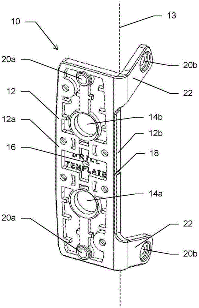
Referring to fig. 1, the guide 10 includes a body 12 having two apertures 14a, 14b, at least a marking indicator 16 and an alignment indicator 18. The two apertures 14a, 14b are for receiving the connector 400 of the latch assembly 500 therethrough, as will be described in more detail below. The body 12 further comprises a reference axis 13 which, in use, is arranged to be aligned in the direction of the door or post when the guide 10 facilitates installation of the latch assembly. Alignment indicator 18 and marking indicator 16 may be aligned in a plane substantially perpendicular to the reference axis. The reference axis 13 may be defined by at least a portion of an edge of the body 12.
Depending on the orientation of the latch 200 during the installation process, i.e., on either the left or right pivoting doors, only one of the two apertures 14a, 14b is required to allow the latch 200 to be operatively connected to the remote actuator unit 300. Details of the installation of the latch 100 will be described in more detail below. However, it is contemplated that two apertures 14a, 14b are provided so that a user may select according to their preference for either the left pivoting door or the right pivoting door.
As shown, two apertures 14a, 14b are located on the main portion 12a of the body 12, and the alignment indicator 18 is located on an edge 12b of the body 12, where the edge is formed on the main portion of the body 12. Each aperture 14a, 14b is spaced from the index indicator, and in the embodiment shown, each aperture 14a, 14b is positioned equidistant or symmetrically from the index indicator 16. In the embodiment shown, the two orifices 14a, 14b are located on the same vertical plane.
As shown, the marking indicator 16 is located on the main portion 12a of the body 12. In the illustrated embodiment, the indicia indicator 16 is located on the central longitudinal axis of the body 12 such that the positions of the two apertures 14a, 14b may be in mirror image orientations when the body is rotated substantially about 180 °.
As shown in fig. 1, the guide 10 further comprises at least one flange 22 turned from the main portion 12a of the body 12, wherein the at least one flange 22 comprises an inner surface and is arranged to be aligned with the reference axis 13 of the body 12 with respect to the column 100 in use by abutment of the inner surface against the column. In the illustrated embodiment, the guide 10 comprises two flanges extending substantially perpendicularly from the main portion 12a of the body 12, such that, in use, the reference axis 13 is aligned with one or more internal corners formed between the at least one flange 22 and the main portion 12a of the body 12. The main portion 12a and the flange 22 include apertures 20a, 20b, respectively, to allow the latch 100 to be secured to a door or post via the guide 10 using suitable fastening means, such as mechanical fasteners, including screws, bolts, rivets, etc. Details of the installation of the latch 200 will be described in more detail below.
Fig. 2 to 13d show method steps of installing the guide 10, which guide 10 is to be used as a guide for making at least one aperture 106, 108 in the post 100 for installing the latch 200 and the remote actuator unit 300.
As shown in fig. 2, the guide 10 is mounted to a corner of the post 100, whereby the body 12 abuts a front face 100a of the post 100 and the two flanges 22 abut a side face 100b of the post 100. As shown, the indicia indicator 16 is a preformed hole in the body 12 that allows for the formation of a position mark 102 on the front face 100a of the post 100. The position markings 102 may be generated using a suitable device such as a pen, pencil, or center-punch. Advantageously, if the post 100 is made of a soft material such as wood or PVC, the guide 10 may be temporarily secured to the post 100 by the marking indicator 16 using a nail.
Referring to FIG. 3, a temporary line 104 is depicted that extends from the alignment indicator 18 across the side 100b, such that the line 104 is substantially perpendicular to the front 100 a. A protractor or carpenter's ruler may be used to ensure that the line 104 is substantially perpendicular to the front face 100 a.
As shown in fig. 4, the guide 10 is inverted and mounted to the rear corner of the post 100, whereby the body 12 abuts the rear face 100c of the post 100 and the two flanges 22 abut the sides 100b of the post 100. As shown, with the alignment indicator 18 substantially aligned with the line 104, the second position indicia 102 is formed on the back side 100c of the post 100 such that the position indicia 102 on the front side 100a and the back side 100c lie substantially on a common axis. The combination of the position marker 102 and the line 104 allows the first aperture 106 and the second aperture 108 to lie substantially on a common axis.
As shown in fig. 5 and 6, the guide 10 is removed, showing the position markings 102 on the front and back sides 100a, 100c of the post 100. A first aperture 106 is drilled through the position mark 102 on the front face 100a of the post 100. A second aperture 108 is drilled through the location mark 102 on the back side 100c of the post 100. The combination of the position marker 102 and the line 104 may be used as a reference or reference point to improve the accuracy of the mounting by allowing the first and second apertures 106, 108 to lie substantially on a common axis extending horizontally through the column.
Once the first and second apertures 106, 108 are drilled into the column 100, the guide 10 is installed with one of a latch or a remote actuation unit to mount the assembly on the column 100. In the embodiment shown, the guide 10 is removed and mounted to the rear of the latch 200. As shown in fig. 7a and 7b, the guide 10 is mounted in the form of a base plate to the rear of the latch 200 to assemble the latch subassembly 500. Advantageously, the use of the guide as a base plate in conjunction with the latch eliminates the need for additional tools to mount the latch assembly and minimizes errors in human measurement.
The rear of the latch 100 receives a connector portion 202 that is substantially concentric with the first aperture 14 a. As shown in fig. 7b, the connector portion 202 protrudes through the guide 10, which will be described in more detail below. Advantageously, the rear of the latch 200 may be provided with locating means 204a, 204b to inter-engage with corresponding inter-engaging means provided on the guide 10 to ensure correct fitting/alignment. As shown in fig. 7a, the positioning device 204b is concentric with the second aperture 14 b.
Advantageously, suitable fastening means such as screws, snap-fits, friction fittings and the like may be used to secure the guide 10 to the rear of the latch 200.
Once the guide 10 is mounted to the rear of the latch 200, the user cuts the connector 400 to size. As shown in fig. 8a and 8b, the connector 400 includes a ball connector 402 at one end and a series of linear wire measurements 404, e.g., metric measurements on one face and english measurements on the other face, whereby the series of linear wire measurements 404 may begin with the ball connector 402. The user would measure the depth x of the post 100 and cut the length of the connector 400 to length x.
Once the connector 400 is cut to size, the connector 400 is connected to the female connector portion 302 of the remote actuator unit 300 via a connector 402, as shown in fig. 9a and 9 b. Advantageously, the connector portion 402 is snap-fit into the female connector portion 302. As shown in fig. 9c, the connector portion 402 may include a ball joint that allows the connector 400 to be pivotally connected to the female connector portion 302 to tilt or accommodate any misalignment or offset between the two apertures 106, 108, as will be described in more detail below.
Once the connector 400 is connected to the remote actuator unit 300, the remote actuator unit 300 is mounted to the back side 100c of the post 100, as shown in fig. 10 a. As shown, the connector 400 passes through both apertures 106, 108 such that the end of the connector 400 is located in the aperture 108. And, the latch 100 is mounted to the guide 10 to form a latch subassembly 500. As shown in fig. 10b, the button 306 on the remote actuator unit 300 is pressed to allow the end of the connector 400 to protrude from the front face 100a, presenting itself to the connector portion 202 of the latch 200. Fig. 11 shows the latch subassembly 500 and the remote actuator unit 300 mounted on the post 100, and the connector 400 is adapted to be inserted into the latch 200 and capable of mating with the remote actuator unit 300 via the apertures 106, 108. As described above, the ball joint 402 allows the connector 400 to be pivotably connected to the female connector portion 302 to accommodate any misalignment between the two apertures 106, 108 so that the latch 200 and the remote actuator unit 300 are still operatively connected by the connector 400.
Further, as shown in fig. 8a to 9b, the connector 400 has a cross-sectional profile 406, which cross-sectional profile 406 allows the profiles 206, 304 to engage with the respective connector portions 202, 302. This may provide a positive axial and/or rotational drive between the remote actuator unit 300 and the latch 200. Advantageously, the remote actuator unit 300 may be used to lock/unlock the latch 200 and to unlatch the latch 200.
Fig. 12a is an isometric view showing the latch subassembly 500 and the remote actuator unit 300 mounted on the post 100, whereby the latch 200 engages a striker (not shown) to hold a movable barrier or door (not shown) closed. Once installed, the wires 104 may be removed. Alternatively, the latch 200 and remote actuator unit 300 may be mounted to a movable barrier or door (not shown), while a striker (not shown) may be mounted to the post 100. As shown, both the guide 10 and the latch 200 are fixed to the post 100, whereby the flange 22 of the device forms a side fixing leg.
As shown in FIG. 12a, once installed, the alignment indicator 18 is offset from the line 104. However, as shown in fig. 10 a-10 c, the apertures 106, 108 lie substantially on a common axis to enable the latch subassembly 500 and the remote actuator unit to be operatively connected by the connector 400.
While fig. 2 to 12a show the guide 10 oriented to allow the latch 200 to be mounted on the right corner of the post 100, it is also contemplated that the guide 10 could be inverted to allow the latch 200 to be mounted on the left corner of the post 100, as shown in fig. 12 b. In this case, the latch assembly 500 may be configured to operate or be mounted on a left or right hand pivoting door. This arrangement is achieved by arranging or positioning the two apertures 14a, 14b equidistant or symmetrical to the indicia indicator 16.
As described above, once installed, the alignment indicator 18 is offset from the line 104. Fig. 12c shows another embodiment whereby a series of mounting indicia 50, 52 are provided on both the guide 10 and the remote actuator unit 300 to confirm that the latch subassembly 500 and the remote actuator unit 300 are properly mounted and aligned with the wire 104. As shown in fig. 12c, two mounting indicia 50 are provided on the guide 10 and they are equally spaced from the alignment indicator 18. Similarly, two mounting indicia 52 are provided on the guide 10 and are equally spaced from the centerline 54 of the remote actuator unit 300.
As shown in fig. 12c, the alignment indicator 18 is a recess, so advantageously, the series of mounting indicia 50, 52 may be protrusions or raised ribs to prevent confusion during the mounting process. If the alignment indicator 18 is a protrusion or raised rib, the series of mounting indicia 50, 52 may be recesses. Although the above embodiments disclose two sets of mounting indicia 50, 52 provided on the guide 10 and the remote actuator unit 300, respectively, it is also contemplated that only one set of mounting indicia may be required on the guide 10 or on the rear actuator unit 300.
Fig. 13a to 13d show an alternative method of mounting the latch 200 and remote actuator unit 300 to the post 100. As shown in fig. 13a, the connector 400 is connected to the remote actuator unit 300, wherein the remote actuator unit 300 is mounted to the back side 100c of the post 100. Fig. 13b shows the connector 400 sized so that the end connector 400 will be substantially flush with the front face 100a of the post 100. As shown in fig. 13c, the button 306 on the remote actuator unit 300 is pressed to allow the end of the connector 400 to protrude from the front face 100a to present itself to the connector portion 202 of the latch 200. As shown in fig. 13d, a latch subassembly 500 (including the guide 10 in the form of a back plate of the latch 200) and a remote actuator unit 300 are shown mounted to the post 100 and operatively connected by a connector 400.
Fig. 14 is an isometric view of a guide according to another embodiment of the invention, wherein the guide 10 includes a body 12 having two apertures 14a, 14b, two marking indicators 16a, 16b, and two alignment indicators 18a, 18b, wherein each alignment indicator 18a, 18b is located substantially on the same plane as its respective marking indicator 16a, 16 b. The guide shown in fig. 14 may also be mounted, for example, to form the base plate of a latch or remote actuating unit.
As shown, the body 12 includes a frangible portion 30a, 30b that covers each aperture 14a, 14b, which is removable from the body 12. Each frangible portion 30a, 30b has the indicia indicator 16a, 16b whereby each indicia indicator 16a, 16b and its respective aperture 14a, 14b lie on a common axis extending longitudinally along the body.
During installation, the frangible portions 30a, 30b can be removed to allow the latch 100 to be operatively connected to the remote actuator unit 200. As described above, depending on the orientation of the latch assembly 100 during the installation process, i.e., on the left or right pivoting doors, one of the two frangible portions 30a, 30b may be removed to allow the latch 200 to be operatively connected to the remote actuator unit 300.
As shown, the frangible portions 30a, 30b extend substantially across their respective apertures 14a, 14 b. Advantageously, the frangible portion 30a, 30b may be connected to the body by at least one snap tab or reduced portion to enable easy removal of the member 30a, 30b during installation.
In addition, each frangible portion 30a, 30b includes a second indicia indicator 32a, 32b, whereby the second indicia indicator 32a, 32b is offset from the first indicia indicator 16a, 16b by the thickness of the flange 22. It is contemplated that the second indicia indicators 32a, 32b allow a user to select to fold the flange 22 back into the door or post during installation.
As shown in fig. 15a and 15b, the ball-shaped connector 402 of the connector 400 is snap-fit into the female connector portion 302 of the connector 304. A flange 308 is provided in the female connector portion 302 to limit or prevent disconnection of the ball connector 402. The cross-sectional profile 406 of the connector 400 engages with the complementary profile 304 of the connector 304 to provide a positive axial and/or rotational drive between the remote actuator unit 300 and the latch 100. Further, the ball connector 402 allows the connector 400 to be pivotally connected to the female connector portion 302 to tilt or accommodate any misalignment or deviation between the two apertures 106, 108. As shown in fig. 15b, the female connector portion 302 is connected to a key cylinder 310 that is received in a push button 306, such that the push button 306 of the remote actuator unit 300 can be used to lock/unlock the latch 200, as well as to unlatch the latch 200.
Fig. 16-17 b schematically illustrate further embodiments of the present disclosure whereby electronic or electromechanical interfaces 312, 312a, 312b, 312c and 312d may be used on the remote actuator unit 300 instead of the buttons 306. As shown in fig. 16, connector 400 is connected to female connector portion 302 of remote actuator unit 300. Figures 17 a-17 d illustrate various embodiments of the electronic or electromechanical interfaces 312a, 312b, 312c, and 312 d.
In FIG. 17a, a contactless electronic interface is used, whereby wireless, Wi-Fi, RFID, NFC or wireless can be used
Communication to lock/unlock the
latch 200 and to unlatch the
latch 200. In this embodiment, at least one
status LED 314 is used to provide status of the
remote actuator unit 300, such as a low battery warning or positive or negative readings confirming the contactless device.
In fig. 17b, a combination contactless and PIN electronic interface 312a is used, whereby a PIN number is granted to a third party or guest for temporary access. In this embodiment, the homeowner will have permanent access, and this can be achieved by using a unique PIN or contactless device. Interface 312b includes a numeric keypad having at least a series of command buttons. The interface 310b may be a touch screen with a status indicator such as a battery (charge level) level or signal strength indicator.
In the embodiment of fig. 17a and 17b, the
electronic interfaces 312a, 312b of the
remote actuator unit 300 may be used to lock/unlock the latch 20 and unlatch the
latch 200 to allow keyless entry with minimal user interaction. In the embodiment of FIG. 17b, wireless, NFC or smart phone may be employed
Functions to lock/unlock the
latch 200 and to unlatch the
latch 200.
In the embodiment of fig. 17c and 17d, the release mechanism may be operated using the electronic interface 312c, 312d of the remote actuator unit 300 to allow the knob 216 to unlock the latch 200 and/or unlatch the latch 200.
In the embodiment of fig. 17 a-17 c, the electronic or electromechanical interfaces 312a, 312b, and 312c may be battery powered, and emergency power terminals (not shown) may be provided to "jump start" the remote actuator unit 300 when the battery is depleted. In the embodiment of fig. 17d, the knob 316 may further include a key cylinder that may be used to override the electromechanical interface 312d when the battery is depleted.
In the embodiment of fig. 16-17 d, the electronic or electromechanical interfaces 312, 312a, 312b, 312c, and 312d may be directly or indirectly wirelessly connected to the LAN.
Applications of
Although the embodiments disclose a latch and system for use on a door, it is contemplated that the latch and system may be used in other applications, such as security fences, area restraining fences, gates, security barriers, nursing homes, gardens, swimming pools, child care applications, and the like.
Alternative embodiments
Example 1: a latch assembly mountable to a structure including a latch, a remote actuation unit and a guide formed separately from the latch and the remote actuation unit, the latch and the remote actuation unit being arranged to be connected via at least one aperture formed in the structure, and wherein the guide is adapted to facilitate mounting of the latch assembly, wherein, upon mounting the assembly on the structure, the guide mounts one of the latch or the remote actuation unit.
Example 2: the latch assembly of embodiment 1 wherein the guide forms a base plate of the latch or remote actuation unit.
Example 3: the latch assembly of embodiment 1 or 2 wherein the guide comprises a body having at least one indicia indicator and at least one alignment indicator to facilitate forming the at least one aperture in the structure.
Example 4: the latch assembly of embodiment 3 wherein the body further comprises a reference axis arranged, in use, to be aligned in the direction of the structure when the guide facilitates installation of the latch or remote actuation unit.
Example 5: the latch assembly of embodiment 4, wherein the at least one indicia indicator and the at least one alignment indicator are aligned in a plane substantially perpendicular to the reference axis.
Example 6: a guide for mounting a latch assembly on a structure, the guide comprising a body having at least one indicia indicator and at least one alignment indicator, and the body comprising a reference axis, wherein the at least one indicia indicator and the at least one alignment indicator are aligned in a plane substantially perpendicular to the reference axis.
Example 7: the latch assembly or guide of any of embodiments 4 to 6 wherein, in use, the reference axis is arranged to be aligned on or substantially parallel to an edge of the structure.
Example 8: the latch assembly or guide of any of embodiments 4-7, wherein the reference axis is defined by at least a portion of an edge of the body.
Example 9: the latch assembly or guide of any of embodiments 4-8 wherein the body comprises a main portion and further comprising at least one flange turned from the main portion of the body, the at least one flange comprising an inner surface, wherein, in use, the at least one flange is arranged to align a reference axis of the body relative to the structure by the inner surface abutting the structure.
Example 10: the latch assembly or guide of embodiment 9, wherein the at least one flange extends substantially perpendicularly from the main portion of the body such that, in use, the reference axis is aligned with one or more interior corners formed between the at least one flange and the main portion of the body.
Example 11: the latch assembly or guide of any of embodiments 3-10, wherein the at least one alignment indicator is located on an edge of the body.
Example 12: the latch assembly or guide of embodiment 11, when dependent on embodiment 9, wherein the edge is formed on a main portion of the body.
Example 13: the latch assembly or guide of any of embodiments 3-12, wherein the at least one indicia indicator is defined by a preformed hole formed in the body.
Example 14: the latch assembly or guide of any of embodiments 3-13, wherein the body includes at least one aperture to receive a connector of the latch assembly therethrough.
Example 15: the latch assembly or guide of embodiment 14, when dependent on embodiment 13, wherein the at least one preformed hole is concentric with the at least one aperture.
Example 16: the latch assembly or guide of embodiment 15, further comprising a frangible portion comprising at least one preformed hole that covers the at least one aperture and is removable from the body.
Example 17: the latch assembly or guide of any of embodiments 16 wherein the body includes two apertures and each aperture is equally spaced from the central axis such that when the body is rotated substantially about 180 °, the positions of the two apertures are in a mirror image orientation.
Example 18: the latch assembly or guide of embodiment 14, when dependent on embodiment 13, wherein the preformed hole is spaced apart from the at least one aperture.
Example 19: the latch assembly or guide of embodiment 18, wherein the body includes two apertures and each aperture is equally spaced from the preformed hole such that when the body is rotated substantially about 180 °, the positions of the two apertures are in a mirror image orientation.
Example 20: the latch assembly of any preceding embodiment, further comprising a connector for connecting the latch to a remote actuation unit.
Example 21: the latch assembly of embodiment 20, wherein the connector is adapted to be inserted into the latch and is cooperable with the remote actuation unit via the at least one aperture.
Example 22: a latch assembly according to any preceding embodiment in which the remote actuation unit comprises a button and a key cylinder for locking/unlocking and/or unlatching the latch.
Example 23: the latch assembly of any of the preceding embodiments 1-21, wherein the remote actuation unit comprises an electronic or electromechanical interface for locking/unlocking and/or unlatching the latch.
Example 24: the latch assembly of embodiment 23 wherein the remote actuation unit is operable by a non-contact means.
Example 25: the latch assembly of embodiment 24 wherein the remote actuation unit may be wirelessly connected, directly or indirectly, to a LAN.
Example 26: a method of installing a latch assembly for a structure, the latch assembly including a latch, a remote actuating unit, and a guide formed separately from the latch and the remote actuating unit, the method comprising:
positioning a guide on the structure, wherein the guide is adapted to facilitate installation of the latch assembly;
the latch or remote actuating unit is mounted to the guide when the assembly is mounted to the structure.
Example 27: the method of embodiment 26, further comprising interconnecting the latch and the remote actuation unit via a connector extending through an aperture formed in the guide.
Example 28: the method of embodiment 27, further comprising: aligning apertures to be formed in opposing faces of the structure via the guides, wherein the aligned apertures are positioned along a common axis, wherein the apertures receive the connectors.
Example 29: a method of installing a latch assembly for a structure, the latch assembly including a latch, a remote actuating unit, and a guide formed separately from the latch and the remote actuating unit, the method comprising:
structurally positioning a guide defining a reference plane adapted to facilitate installation of the latch assembly;
a first aperture and a second aperture are formed on opposite sides of the structure, wherein the aligned apertures are located along a common axis, the apertures being arranged to align on a reference plane defined by the guide means.
Example 30: the method of embodiment 29, wherein the guide comprises a body having at least one marking indicator and at least one alignment indicator, and the body comprises a reference axis, wherein the at least one marking indicator and the at least one alignment indicator are aligned in a plane that is substantially perpendicular to the reference axis and defines a reference plane for mounting the latch assembly.
Example 31: the method of embodiment 30, further comprising aligning a reference axis of the guide with an edge of the structure.
Example 32: the method of embodiment 30, further comprising marking the first face of the structure with the at least one marking indicator and forming a first aperture at or near the marking.
Example 33: the method of embodiment 32, further comprising marking the second side of the structure using the at least one alignment indicator.
Example 34: the method of embodiment 33, further comprising: the guide is aligned on a third surface using the alignment mark, wherein the third surface is disposed opposite to the first surface.
Example 35: the method of embodiment 33, further comprising: marking a third face of the structure using the at least one marking indicator; and forming a second aperture at or near the indicia on the third face, wherein the first aperture and the second aperture are aligned in the reference plane and along the common axis to receive the connector.
Example 36: the latch assembly of embodiment 35, further comprising connecting a connector to the latch and the remote actuation unit via the aligned apertures.
Example 37: the method according to any one of embodiments 29-36, wherein the body comprises a main portion, and further comprising at least one flange turned from the main portion of the body, the at least one flange comprising an inner surface, and the method further comprises positioning the reference axis relative to the structure by abutting the inner surface against the structure.
Example 38: the method of embodiment 37, wherein the at least one flange extends substantially perpendicularly from the main portion of the body, and the method further comprises: the reference axis is defined by one or more interior corners formed between the at least one flange and the main portion of the body.
Example 39: a guide for mounting a latch assembly on a structure, the latch assembly comprising a latch, a remote actuating unit and being formed separately from the latch and the remote actuating unit, the guide being adapted to facilitate mounting of the latch assembly, wherein the guide is integrated as part of the latch or the remote actuating unit when the latch assembly is mounted on the structure.
Example 40: the guide of embodiment 39, wherein the guide forms a base plate of a latch or remote actuation unit.
Example 41: the guide of embodiment 38, further as defined in any one of embodiments 6-19.
In the appended claims and the preceding disclosure, unless the context requires otherwise due to express language or necessary implication, the word "comprise" or variations such as "comprises" or "comprising" is used in an inclusive sense, i.e. to specify the presence of the stated features but not to preclude the presence or addition of further features in various embodiments of the disclosure.
Thus, the present disclosure is not limited to the particular embodiments described herein, which are intended as illustrations of various aspects. As will be apparent to those skilled in the art, many modifications and variations are possible without departing from the scope thereof. Functionally equivalent methods and apparatuses within the scope of the disclosure, in addition to those enumerated herein, will be apparent to those skilled in the art from the foregoing descriptions. Such modifications and variations are intended to fall within the scope of the appended claims. The disclosure is to be limited only by the terms of the appended claims, along with the full scope of equivalents to which such claims are entitled. It will be understood that the present disclosure is not limited to a particular method, which can, of course, vary. It is also to be understood that the terminology used herein is for the purpose of describing particular embodiments only, and is not intended to be limiting.
From the foregoing, it will be appreciated that various embodiments of the disclosure have been described herein for purposes of illustration, and that various modifications may be made without deviating from the scope and spirit of the disclosure. Therefore, the various embodiments disclosed herein are not intended to be limiting, with the true scope being indicated by the following claims.