CN112710565A - Channel on-site shearing force experimental device and method for lossless concrete - Google Patents
Channel on-site shearing force experimental device and method for lossless concrete Download PDFInfo
- Publication number
- CN112710565A CN112710565A CN202011488638.6A CN202011488638A CN112710565A CN 112710565 A CN112710565 A CN 112710565A CN 202011488638 A CN202011488638 A CN 202011488638A CN 112710565 A CN112710565 A CN 112710565A
- Authority
- CN
- China
- Prior art keywords
- force
- bolt
- channel
- shear
- rectangular
- Prior art date
- Legal status (The legal status is an assumption and is not a legal conclusion. Google has not performed a legal analysis and makes no representation as to the accuracy of the status listed.)
- Granted
Links
- 238000010008 shearing Methods 0.000 title claims abstract description 71
- 238000000034 method Methods 0.000 title claims description 28
- 238000006073 displacement reaction Methods 0.000 claims abstract description 28
- 238000012360 testing method Methods 0.000 claims abstract description 27
- 230000001066 destructive effect Effects 0.000 claims abstract 2
- 238000006243 chemical reaction Methods 0.000 claims description 52
- 238000002474 experimental method Methods 0.000 claims description 16
- 230000007246 mechanism Effects 0.000 claims description 15
- 229910000831 Steel Inorganic materials 0.000 claims description 10
- 239000010959 steel Substances 0.000 claims description 10
- 230000008859 change Effects 0.000 claims description 5
- 230000008569 process Effects 0.000 claims description 5
- 239000010687 lubricating oil Substances 0.000 claims description 3
- 239000011248 coating agent Substances 0.000 claims 1
- 238000000576 coating method Methods 0.000 claims 1
- 230000035882 stress Effects 0.000 description 55
- 238000009434 installation Methods 0.000 description 7
- 238000010586 diagram Methods 0.000 description 5
- 238000005516 engineering process Methods 0.000 description 5
- 230000008878 coupling Effects 0.000 description 4
- 238000010168 coupling process Methods 0.000 description 4
- 238000005859 coupling reaction Methods 0.000 description 4
- 238000001514 detection method Methods 0.000 description 3
- 230000006355 external stress Effects 0.000 description 2
- 238000011065 in-situ storage Methods 0.000 description 2
- 230000000149 penetrating effect Effects 0.000 description 2
- 238000004873 anchoring Methods 0.000 description 1
- 230000009286 beneficial effect Effects 0.000 description 1
- 238000010276 construction Methods 0.000 description 1
- 238000005536 corrosion prevention Methods 0.000 description 1
- 238000012986 modification Methods 0.000 description 1
- 230000004048 modification Effects 0.000 description 1
- 238000009417 prefabrication Methods 0.000 description 1
- 238000007660 shear property test Methods 0.000 description 1
- 238000004088 simulation Methods 0.000 description 1
- 230000007704 transition Effects 0.000 description 1
Images




Classifications
-
- G—PHYSICS
- G01—MEASURING; TESTING
- G01N—INVESTIGATING OR ANALYSING MATERIALS BY DETERMINING THEIR CHEMICAL OR PHYSICAL PROPERTIES
- G01N3/00—Investigating strength properties of solid materials by application of mechanical stress
- G01N3/24—Investigating strength properties of solid materials by application of mechanical stress by applying steady shearing forces
-
- G—PHYSICS
- G01—MEASURING; TESTING
- G01N—INVESTIGATING OR ANALYSING MATERIALS BY DETERMINING THEIR CHEMICAL OR PHYSICAL PROPERTIES
- G01N3/00—Investigating strength properties of solid materials by application of mechanical stress
- G01N3/02—Details
-
- G—PHYSICS
- G01—MEASURING; TESTING
- G01N—INVESTIGATING OR ANALYSING MATERIALS BY DETERMINING THEIR CHEMICAL OR PHYSICAL PROPERTIES
- G01N2203/00—Investigating strength properties of solid materials by application of mechanical stress
- G01N2203/0014—Type of force applied
- G01N2203/0025—Shearing
-
- Y—GENERAL TAGGING OF NEW TECHNOLOGICAL DEVELOPMENTS; GENERAL TAGGING OF CROSS-SECTIONAL TECHNOLOGIES SPANNING OVER SEVERAL SECTIONS OF THE IPC; TECHNICAL SUBJECTS COVERED BY FORMER USPC CROSS-REFERENCE ART COLLECTIONS [XRACs] AND DIGESTS
- Y02—TECHNOLOGIES OR APPLICATIONS FOR MITIGATION OR ADAPTATION AGAINST CLIMATE CHANGE
- Y02E—REDUCTION OF GREENHOUSE GAS [GHG] EMISSIONS, RELATED TO ENERGY GENERATION, TRANSMISSION OR DISTRIBUTION
- Y02E30/00—Energy generation of nuclear origin
- Y02E30/30—Nuclear fission reactors
Landscapes
- Physics & Mathematics (AREA)
- Health & Medical Sciences (AREA)
- Life Sciences & Earth Sciences (AREA)
- Chemical & Material Sciences (AREA)
- Analytical Chemistry (AREA)
- Biochemistry (AREA)
- General Health & Medical Sciences (AREA)
- General Physics & Mathematics (AREA)
- Immunology (AREA)
- Pathology (AREA)
- Investigating Strength Of Materials By Application Of Mechanical Stress (AREA)
Abstract
The invention discloses a non-destructive concrete channel on-site shearing force experimental device and a testing method, which are mainly used for on-site shearing tests of channels without stressed supporting points, which are installed on concrete in a tunnel. The two displacement sensor fixed blocks are respectively contacted with one ends of the two shearing stress loading blocks. Utilize the channel body as shear test atress strong point, through driving force bolt, atress connecting bolt, shearing atress loading piece and the effective connection of rectangle power connection switching groove, become the inside shearing force of system through the rotatory fastening of power driving force bolt to the shearing force that originally needs outside atress to support just can the loading, rethread force sensor and displacement sensor and then record the shearing force of embedded channel or outward appearance channel.
Description
Technical Field
The invention belongs to the technical field of on-site detection of embedded channels and externally-hung channels, relates to a channel on-site shearing force experimental device and method for nondestructive concrete, and is particularly used for on-site shearing test of nondestructive concrete of embedded channels and externally-hung channels which are embedded and installed in tunnels.
Background
At present, the channel technology is mainly divided into a pre-buried channel technology and an externally-hung channel technology. The embedded chute technology is characterized in that C-shaped channel steel is embedded in concrete in the process of prefabricating the concrete in a tunnel, the external hanging channel technology is characterized in that a channel is externally hung and fixed on an embedded sleeve or an anchor bolt, and cables, pipelines, equipment and the like are fixed on a shield pipe piece through T-shaped bolts during later electromechanical installation.
In actual use, the channel is not only subjected to axial stretching acting force, but also longitudinal and transverse shearing acting forces, and due to the difference between the installation and anchoring conditions under laboratory conditions and on-site construction conditions, the channel is not only subjected to axial stretching acting force, but also subjected to longitudinal and transverse shearing acting forces. Therefore, in the later period, the embedded channel which is already installed in the concrete in the tunnel or the externally hung channel which is already installed in the tunnel needs to be detected on site.
At present, two situations generally exist in the prefabrication of an embedded channel in concrete, one is to directly embed in a pipe piece field, and the embedded channel is installed in a tunnel together with pipe pieces in the later period; the other method is that the concrete is directly cast in situ and installed in the concrete in the tunnel when the concrete is cast in situ in the tunnel. And the external hanging groove is directly externally hung on concrete in the tunnel.
There is provided a pre-buried channel device for shear test in utility model patent (CN208171764U), but the device buries the spout sample in advance in the concrete in the laboratory, only simulates pre-buried channel in-service operating mode, and the shearing force that its device surveyed can not represent the actual shearing force that receives of the pre-buried spout of on-the-spot shield segment more. But also is not suitable for on-site shearing of the externally hung channel.
Utility model (CN207779832U) provides a multi-functional buried channel shearing force test frock, and the device is only simulation T type bolt and the spout shearing force between the spout among the spout at T type bolt-up, and is not carried out the spout and is pre-buried among the concrete.
The invention provides a shearing test device of a pre-buried channel on a shield segment and a detection method thereof in the patent of invention (CN 110132759A), wherein the method and the shearing device are mainly applied to the channel pre-buried in the shield segment, the method mainly utilizes a grabbing and lifting head with threads on the segment as a supporting point of a reverse force, the supporting point is the key that the device can be fixedly arranged on the segment and provides a reverse acting force, and the core factor of the method is that an additional reverse force fixing point is required on the segment. Due to stray current and the requirements of corrosion prevention and attractiveness, the grabbing and lifting head can be closed after the duct piece enters the tunnel, so that the method is not suitable for detecting the pipe piece entering the pre-buried channel arranged in the tunnel. In addition, the rectangular tunnel made by cast-in-place concrete is not provided with a grabbing head, and no additional stressed supporting point exists in the tunnel, so that the method is not suitable for the shear test of the embedded channel in the cast-in-place tunnel. The hanging groove is not fixed, so the method is not suitable for the position without the fixed point of the reverse force.
In the prior art, the steel plate is arranged on one side of the width of the duct piece, the duct piece bolt holes and the duct piece are used for fixing the steel plate to be used as counter force, but the duct piece entering the tunnel is assembled, so that the method for fixing the steel plate to be used as the counter force by the duct piece bolt holes and the duct piece bolts becomes impossible.
At present, in the tunnel, the external stress supporting points can be obtained only by means of mechanical anchor bolts, and the method causes additional mechanical damage and damage to the tunnel concrete, so that the service life of the tunnel concrete is shortened. Under the condition of not damaging concrete, the existing method and device can only complete the field detection of the axial tensile bearing capacity of the embedded channel or the externally hung channel, and the method and device capable of completing the longitudinal and transverse shear bearing capacity of the embedded channel or the external channel are lacked. Therefore, there is an urgent need for a method and apparatus for field testing of longitudinal and transverse shearing of pre-buried channels or appearance channels in tunnels without damaging concrete.
Disclosure of Invention
The invention aims to solve the existing technical problems and provides a nondestructive concrete field test shear test method and device for an embedded channel and an externally-hung channel in a tunnel. The method is low in cost and high in cost performance, the problem of shearing test of the embedded channel and the externally hung channel without the stress supporting point on the concrete in the tunnel can be effectively solved, an anchor bolt drawing instrument can be omitted in the test process, and the method is simple in test and convenient to carry.
The invention is realized by the following technical scheme:
the utility model provides a harmless concrete's on-spot shearing force experimental apparatus of channel which characterized in that: the device comprises two shearing stress loading blocks, a driving force bolt, a stress connection conversion mechanism, a stress connecting bolt and a displacement sensor for measuring the position change of the two shearing stress loading blocks, wherein the two shearing stress loading blocks are fixed on a channel to be detected through a T-shaped bolt, the driving force bolt, the stress connection conversion mechanism and the stress connecting bolt are sequentially arranged between the two shearing stress loading blocks, one end of the driving force bolt is connected with the shearing stress loading block at the corresponding end through thread fit, the other end of the driving force bolt is connected with the stress connection conversion mechanism through a revolute pair, the stress connection conversion mechanism is connected with the shearing stress loading block at the corresponding end through the stress connecting bolt, the relative positions of the stress connection conversion mechanism and the shearing stress loading block at the two ends of the driving force bolt can be changed in the process of screwing the driving force bolt by external force, and the conversion, and a force sensor for detecting the shearing force is arranged between the stressed connection conversion mechanism and the stressed connecting bolt.
Further, the two shear stress loading blocks have the same structure and respectively comprise an internal threaded hole and a through hole for being installed on the channel, and the axes of the internal threaded hole and the through hole are perpendicular to each other.
Further, drive power bolt one end be equipped with cut the external screw thread that internal thread hole matches on the atress loading piece, the other end be with the connecting portion that the shifter links to each other is connected in the atress, drive power bolt middle part is equipped with the atress portion of being convenient for exert external force.
Further, the force receiving portion is a polygonal column coaxial with the driving force bolt.
Furthermore, the force-bearing connection conversion mechanism is a rectangular force-bearing connection conversion groove, connecting holes are formed in two ends of the rectangular force-bearing connection conversion groove, one connecting hole is connected with the driving force bolt, the connecting portion on the driving force bolt is a cylindrical head portion with the size larger than that of the connecting hole, and the other connecting hole is used for being connected with the force-bearing connecting bolt.
Further, atress connecting bolt one end is equipped with the rectangle head, and the other end is equipped with the external screw thread, rectangle head one end is installed at rectangle power and is connected the converting groove, and external screw thread one end links to each other with the internal thread hole on shearing atress loading piece, force transducer is gasket type pressure sensor, gasket type pressure sensor cover is located on the atress connecting bolt, and is located between the inboard tip of rectangle head and rectangle power connection converting groove.
Furthermore, the side face of the rectangular head is provided with a positioning screw hole, and the rectangular force connection conversion groove is provided with a corresponding fixing hole.
Furthermore, the rectangular force connection conversion groove is formed by detachably connecting four steel plates through bolts.
Further, lubricating oil for reducing friction is coated between the cylindrical head of the driving force bolt and the inner end of the rectangular force connection conversion groove.
The pressure sensor and the displacement sensor are respectively connected with the data acquisition unit, and the force and displacement data are recorded through the data acquisition unit.
A shear experiment method utilizing the channel field shear force experiment device is characterized by comprising the following steps:
and 5, screwing the driving force bolt through external force, collecting displacement data of the displacement sensor and pressure data detected by the gasket type pressure sensor, and finishing a shearing experiment.
The invention has the beneficial effects that:
the invention utilizes the channel body as a stress supporting point of a shear test, skillfully changes shear force which can be loaded only by external stress support into internal shear force of a system through the rotation and fastening of the force driving force bolt through the effective connection of the driving force bolt, the stress connecting bolt, the shear stress loading block, the rectangular force connection conversion groove, the pressure sensor and the displacement sensor, and then measures the shear force and displacement data of the embedded channel or the externally hung channel through the pressure sensor and the displacement sensor which are arranged in the system. The method perfectly solves the problem that the pre-buried channel and the appearance channel in the tunnel cannot be subjected to a shear force test without bearing points on concrete. In particular, the on-site shear force test of the cast-in-place type embedded channel under the condition of not damaging concrete becomes possible.
Drawings
Fig. 1 is an installation schematic diagram of a field shearing force experimental device for longitudinal shearing of a pre-buried channel.
Fig. 2 is an installation schematic diagram of a field shearing force experimental device for transverse shearing of a pre-buried channel.
FIG. 3 is an installation schematic diagram of a field shearing force experimental device for longitudinal shearing of an externally hung channel.
FIG. 4 is an installation schematic diagram of a field shearing force experimental device for transverse shearing of an externally hung channel.
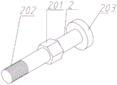
Fig. 5 is a schematic view of a driving force bolt.
FIG. 6 is a schematic view of a force coupling bolt.
FIG. 7 is a schematic view of a rectangular force coupling transition slot.
Fig. 8 is a schematic view of a force sensor.
FIG. 9 is a schematic view of a shear force loading block.
1-a first shear stress loading block, 101-a through hole, 102-an internal threaded hole, 103-a loading block body, 2-a driving force bolt, 201-a stress part, 202-an external threaded head part, 203-a cylindrical head part, 3-a rectangular force connection conversion groove, 301-a fixed hole, 302-a lower connecting hole, 303-an upper connecting hole, 304-a rectangular steel plate, 4-a force sensor, 401-a through hole, 5-a stress connecting bolt, 501-an external threaded head part, 502-a rectangular head part, 503-a positioning screw hole, 6-a displacement sensor, 7-a displacement sensor fixing block, 8-a data collector and 9-a second shear stress loading block.
Detailed Description
Referring to fig. 1 to 9, specific embodiments of the present invention are shown for further explanation of the method of the present invention.
Example 1
The installation schematic diagram of the method is shown in figure 1 (longitudinal shear test of the embedded channel), and the on-site shearing force experimental device for the channel of the lossless concrete comprises a first shearing stress loading block 1, a driving force bolt 2, a rectangular force connection conversion groove 3, a force sensor 4, a stress connection bolt 5, a second shearing stress loading block 9, a displacement sensor 6, a displacement sensor fixing block 7 and a data acquisition unit 8.
Two shearing stress loading blocks are fixed on a channel to be detected through a T-shaped bolt, as shown in figure 1, wherein a first shearing stress loading block 1 is fixed on the upper part of the channel to be detected through the T-shaped bolt, a second shearing stress loading block 9 is fixed on the lower part of the channel to be detected through the T-shaped bolt, a driving force bolt 2, a rectangular force connection conversion groove 3 and a stress connecting bolt 5 are sequentially arranged between the two shearing stress loading blocks, wherein the upper end of the driving force bolt 2 is connected with the first shearing stress loading block 1 through thread fit, the lower end of the driving force bolt is connected with the upper end of the rectangular force connection conversion groove 3 through a revolute pair, the lower end of the rectangular force connection conversion groove 3 is connected with the second shearing stress loading block 9 through the stress connecting bolt 5, and in the process of screwing the driving force bolt 2 by using external force, the relative position of the rectangular force connection conversion groove 3 and, the rectangular force connection conversion groove 3 is used for conversion, the tension change between the first shearing stress loading block 1 and the second shearing stress loading block 9 is changed, so that a shearing force test is carried out, and a force sensor 4 for detecting the shearing force is arranged between the rectangular force connection conversion groove 3 and the stressed connecting bolt 5.
The first shear force loading block 1 and the second shear force loading block 9 have the same structure, and the first shear force loading block 1 is taken as an example for illustration, as shown in fig. 9, the first shear force loading block comprises a rectangular loading block body 103, a through hole 101 for mounting a T-shaped bolt is arranged on the front side surface of the loading block body 103, and an internal thread hole 102 is arranged on the side surface perpendicular to the side surface.
As shown in fig. 5, one end of the driving force bolt 2 is provided with a cylindrical head 203, the other end is provided with an external thread head 202 matching with the internal thread hole 102 of the shear stress loading block, the middle part of the driving force bolt 2 is provided with a stress part 201 matching with the driving wrench, the stress part 201 can be a polygonal column coaxial with the driving force bolt 2, in this embodiment, a hexagonal column, and it should be noted that the size of the stress part 201 needs to be smaller than the upper connection hole 303 on the rectangular force connection conversion slot 3 so as to pass through the hole.
As shown in fig. 7, the rectangular force connection and conversion groove 3 is formed by splicing four rectangular steel plates 304 by bolts, and the upper and lower short steel plates of the rectangular force connection and conversion groove 3 are respectively provided with an upper connection hole 303 and a lower connection hole 302. Two fixing holes 301 are formed in the long steel plate on one side of the rectangular force connection conversion groove 3 and are used for being connected with positioning screw holes 503 of the stressed connecting bolts 5.
As shown in fig. 8, the force sensor 4 is a gasket type pressure sensor, and a through hole 401 for passing the force-receiving connecting bolt 5 is formed in the middle of the force sensor.
As shown in fig. 6, one end of the stressed connecting bolt 5 is provided with an external thread head 501 matched with the shearing stressed loading block, the other end of the stressed connecting bolt is provided with a rectangular head 502 matched with the inner size of the rectangular force connection conversion groove 3, and the side part of the rectangular head 502 is provided with a positioning screw hole 503 corresponding to the fixing hole 301. The displacement sensors 6 are fixed on the outer sides of the two shearing stress loading blocks through the displacement sensor fixing blocks 7, in the embodiment, the number of the displacement sensors 6 is two, the two displacement sensors are respectively located at the top of the first shearing stress loading block 1 and the bottom of the second shearing stress loading block 9, and the two displacement sensors are used for detecting the displacement of the two shearing stress loading blocks.
As shown in fig. 1, a method for testing the nondestructive concrete field test shear of a pre-buried channel in a tunnel, wherein the pre-buried channel is a channel C installed in the concrete in the tunnel, comprises the following steps:
firstly, the stressed connecting bolt 5 penetrates through a through hole 401 of the force sensor 4, then the stressed connecting bolt 5 with the force sensor 4 penetrates through a lower connecting hole 302 on the rectangular force connection conversion groove 3, and finally a fastening bolt penetrates through a fixing hole 301 on a side plate of the rectangular force connection conversion groove 3 and is fixedly connected with a positioning screw hole 503 on the stressed connecting bolt 5.
And (3) connecting and fixing the second shearing stress loading block 9 with the stress connecting bolt 5 (the external thread head part 501 of the stress connecting bolt 5 is connected with the internal thread hole of the second shearing stress loading block 9).
The male screw head 202 of the driving force bolt 2 is inserted through the upper coupling hole 303 of the rectangular force coupling conversion groove 3.
The first shear force loading block 1 is fixedly connected with the driving force bolt 2 (the external thread head 202 of the driving force bolt 2 is connected with the internal thread hole 102 of the first shear force loading block 1).
As shown in fig. 1, a first shear stress loading block 1 and a second shear stress loading block 9 are respectively fixed on an embedded channel C by using T-shaped bolts.
During the experiment, utilize drive spanner clockwise rotation drive power 201 positions on the bolt, along with drive power bolt tightening, drive power bolt to the 1 direction motion of first shearing atress loading piece and then transmit the pulling force for atress connecting bolt 5 and gasket formula pressure sensor through rectangle power connection converting groove 3 to by gasket formula pressure sensor collection atress data.
During the test, the first shearing stress loading block 1 and the second shearing stress loading block 9 are respectively subjected to downward tension and upward tension, and displacement data are collected by the displacement sensor 6. And finally, the displacement sensor 6 and the gasket type pressure sensor transmit the acquired data to the data acquisition unit 8.
Example 2: as shown in fig. 2, the steps of installing and implementing the transverse shear test of the embedded channel, the longitudinal shear test of the external hanging channel, and the transverse shear test are the same as those in embodiment 1, except that the first shear-stressed loading block 1 and the second shear-stressed loading block 9 are respectively installed on the two channels, and are not described again.
It should be noted that the length of the external thread of the driving force bolt 2 and the length of the internal thread of the shear force loading block are sufficient, and the length of the thread which is not screwed into the external thread of the driving force bolt and the internal part of the shear force loading block during the test is sufficient to meet the test requirements.
It should be noted that the cylindrical head 203 of the driving bolt 2 and one side of the rectangular force connection converting groove 3 should be coated with lubricating oil to reduce friction.
It should be noted that the rectangular force connection converting groove 3 must be designed to be rectangular, and the rectangular force connection converting groove 3 does not rotate when the cylindrical head 203 of the driving force bolt 2 rotates.
It should be noted that the head rectangle of the stressed connecting bolt 5 must have the same height and width inside the rectangular force connection conversion slot 3, and when the cylindrical head 203 of the driving bolt 2 rotates, the head rectangle of the stressed connecting bolt 5 perfectly fits with the rectangle inside the rectangular force connection conversion slot 3, and cannot rotate along with the head rectangle.
The above embodiments are merely illustrative of the present invention and are not to be construed as limiting the invention. Although the present invention has been described in detail with reference to the embodiments, it should be understood by those skilled in the art that various combinations, modifications or equivalents may be made to the technical solution of the present invention without departing from the spirit and scope of the technical solution of the present invention, and the technical solution of the present invention is covered by the claims of the present invention.
Claims (10)
Priority Applications (1)
| Application Number | Priority Date | Filing Date | Title |
|---|---|---|---|
| CN202011488638.6A CN112710565B (en) | 2020-12-16 | 2020-12-16 | Channel on-site shear force experimental device and method for nondestructive concrete |
Applications Claiming Priority (1)
| Application Number | Priority Date | Filing Date | Title |
|---|---|---|---|
| CN202011488638.6A CN112710565B (en) | 2020-12-16 | 2020-12-16 | Channel on-site shear force experimental device and method for nondestructive concrete |
Publications (2)
| Publication Number | Publication Date |
|---|---|
| CN112710565A true CN112710565A (en) | 2021-04-27 |
| CN112710565B CN112710565B (en) | 2023-05-23 |
Family
ID=75544002
Family Applications (1)
| Application Number | Title | Priority Date | Filing Date |
|---|---|---|---|
| CN202011488638.6A Active CN112710565B (en) | 2020-12-16 | 2020-12-16 | Channel on-site shear force experimental device and method for nondestructive concrete |
Country Status (1)
| Country | Link |
|---|---|
| CN (1) | CN112710565B (en) |
Cited By (3)
| Publication number | Priority date | Publication date | Assignee | Title |
|---|---|---|---|---|
| CN113959615A (en) * | 2021-11-29 | 2022-01-21 | 华侨大学 | In-situ self-reaction force testing device and method for axial shearing of embedded channel |
| CN113959616A (en) * | 2021-11-29 | 2022-01-21 | 华侨大学 | An in-situ self-reaction force testing device and testing method for transverse shearing of a pre-embedded channel |
| CN114199684A (en) * | 2021-12-23 | 2022-03-18 | 国家石油天然气管网集团有限公司 | Experimental device for be used for demarcating pipeline stress state under external load effect |
Citations (5)
| Publication number | Priority date | Publication date | Assignee | Title |
|---|---|---|---|---|
| JP2002131204A (en) * | 2000-10-27 | 2002-05-09 | Yamaguchi Technology Licensing Organization Ltd | Simple on-site shear test method and device |
| CN207779832U (en) * | 2018-01-26 | 2018-08-28 | 江苏睿中轨道交通装备有限公司 | Multi-functional pre-buried channel flow shearing test tooling |
| CN208171764U (en) * | 2018-05-22 | 2018-11-30 | 中铁检验认证中心 | A kind of pre-buried channel flow shearing test device |
| CN208736747U (en) * | 2019-03-11 | 2019-04-12 | 江苏城工建设科技有限公司 | Pre-buried channel flow and T-bolt shearing slip test device in a kind of tunnel |
| CN110132759A (en) * | 2019-05-29 | 2019-08-16 | 中建八局轨道交通建设有限公司 | The shearing test device and its detection method of pre-buried channel flow on shield duct piece |
-
2020
- 2020-12-16 CN CN202011488638.6A patent/CN112710565B/en active Active
Patent Citations (5)
| Publication number | Priority date | Publication date | Assignee | Title |
|---|---|---|---|---|
| JP2002131204A (en) * | 2000-10-27 | 2002-05-09 | Yamaguchi Technology Licensing Organization Ltd | Simple on-site shear test method and device |
| CN207779832U (en) * | 2018-01-26 | 2018-08-28 | 江苏睿中轨道交通装备有限公司 | Multi-functional pre-buried channel flow shearing test tooling |
| CN208171764U (en) * | 2018-05-22 | 2018-11-30 | 中铁检验认证中心 | A kind of pre-buried channel flow shearing test device |
| CN208736747U (en) * | 2019-03-11 | 2019-04-12 | 江苏城工建设科技有限公司 | Pre-buried channel flow and T-bolt shearing slip test device in a kind of tunnel |
| CN110132759A (en) * | 2019-05-29 | 2019-08-16 | 中建八局轨道交通建设有限公司 | The shearing test device and its detection method of pre-buried channel flow on shield duct piece |
Cited By (3)
| Publication number | Priority date | Publication date | Assignee | Title |
|---|---|---|---|---|
| CN113959615A (en) * | 2021-11-29 | 2022-01-21 | 华侨大学 | In-situ self-reaction force testing device and method for axial shearing of embedded channel |
| CN113959616A (en) * | 2021-11-29 | 2022-01-21 | 华侨大学 | An in-situ self-reaction force testing device and testing method for transverse shearing of a pre-embedded channel |
| CN114199684A (en) * | 2021-12-23 | 2022-03-18 | 国家石油天然气管网集团有限公司 | Experimental device for be used for demarcating pipeline stress state under external load effect |
Also Published As
| Publication number | Publication date |
|---|---|
| CN112710565B (en) | 2023-05-23 |
Similar Documents
| Publication | Publication Date | Title |
|---|---|---|
| CN112710565A (en) | Channel on-site shearing force experimental device and method for lossless concrete | |
| CN111595682B (en) | Large-scale complex surrounding rock condition anchoring and grouting integrated coupling effect test system and method | |
| CN107247020A (en) | A kind of reinforcing bar and concrete drawing experimental rig for eliminating high temperature influence | |
| CN101864845B (en) | Prestress steel rod intelligent anchoring system monitoring dynamic state of strengthening engineering preload | |
| WO2016173112A1 (en) | Multiphase and multi-field coupling anchoring assembly deformation test system and method | |
| WO2007137466A1 (en) | A random, nondestructiv and dynamic testing apparatus and method of the stressed state of a roof bolt | |
| CN114563273B (en) | Mechanical performance test system and evaluation method of bolt combination | |
| CN102928512A (en) | Test method of rock aging deterioration process | |
| CN106124321B (en) | A kind of detachable anchor rod anchored features Testbed | |
| CN110132759B (en) | Shearing test device for pre-buried channel on shield segment and detection method thereof | |
| CN201340385Y (en) | Anchorage body rheological drawing test device | |
| CN102980851B (en) | Cable-stayed bridge cable beam anchorage zone technical condition monitoring windows and observation method | |
| CN108279176B (en) | Apparatus for researching mechanical properties of bolt under impact force and its application method | |
| CN116754382B (en) | A Servo Test Device and Test Method for Energy-Absorbing Anchor Bolt Pull-Out | |
| CN108279107B (en) | Device for researching mechanical properties of dynamic bolt and surrounding rock and its application method | |
| CN105388210B (en) | Suspension cable damage detection apparatus and detection method based on temporary steel diagonal brace | |
| CN109580201B (en) | Testing device and testing method for variable-angle cable-stayed bolt | |
| CN207923406U (en) | Dynamic lower bolt and mechanical character of surrounding rock research device | |
| CN109946155B (en) | Steel bridge welding seam stress real-time monitoring device | |
| CN103104272B (en) | Lossless dynamic detection device of anchor stock preload and detection method thereof | |
| CN210154952U (en) | Shear test device for pre-buried channel on shield segment | |
| CN103868796B (en) | A kind of concrete core sample tensile test locking device | |
| CN201335746Y (en) | Concrete beam anchorage pre-stressing force detecting device | |
| CN203148657U (en) | Device for detecting comprehensive mechanical properties of anchor rods | |
| CN215572686U (en) | Pipeline stress-strain detection sensor and pipeline stress-strain monitoring device |
Legal Events
| Date | Code | Title | Description |
|---|---|---|---|
| PB01 | Publication | ||
| PB01 | Publication | ||
| SE01 | Entry into force of request for substantive examination | ||
| SE01 | Entry into force of request for substantive examination | ||
| GR01 | Patent grant | ||
| GR01 | Patent grant | ||
| CP01 | Change in the name or title of a patent holder | ||
| CP01 | Change in the name or title of a patent holder |
Address after: Two road 430030 in Hubei province in Qiaokou District of Wuhan city Baofeng No. 126 Patentee after: Wuhan Material Protection Research Institute Co., Ltd. of China National Machinery Engineering Corp. Address before: Two road 430030 in Hubei province in Qiaokou District of Wuhan city Baofeng No. 126 Patentee before: WUHAN RESEARCH INSTITUTE OF MATERIALS PROTECTION Co.,Ltd. |