CN112717618B - Dust removal device for flue gas treatment and dust removal method thereof - Google Patents

Dust removal device for flue gas treatment and dust removal method thereof Download PDF

Info

Publication number
CN112717618B
CN112717618B CN202110344173.5A CN202110344173A CN112717618B CN 112717618 B CN112717618 B CN 112717618B CN 202110344173 A CN202110344173 A CN 202110344173A CN 112717618 B CN112717618 B CN 112717618B
Authority
CN
China
Prior art keywords
dust
flue gas
device body
water
smoke
Prior art date
Legal status (The legal status is an assumption and is not a legal conclusion. Google has not performed a legal analysis and makes no representation as to the accuracy of the status listed.)
Active
Application number
CN202110344173.5A
Other languages
Chinese (zh)
Other versions
CN112717618A (en
Inventor
王小平
Current Assignee (The listed assignees may be inaccurate. Google has not performed a legal analysis and makes no representation or warranty as to the accuracy of the list.)
Lugu Jinshi Environmental Protection Engineering Technology Co.,Ltd.
Original Assignee
Hunan Hongtu Intelligent Technology Co ltd
Priority date (The priority date is an assumption and is not a legal conclusion. Google has not performed a legal analysis and makes no representation as to the accuracy of the date listed.)
Filing date
Publication date
Application filed by Hunan Hongtu Intelligent Technology Co ltd filed Critical Hunan Hongtu Intelligent Technology Co ltd
Priority to CN202110344173.5A priority Critical patent/CN112717618B/en
Publication of CN112717618A publication Critical patent/CN112717618A/en
Application granted granted Critical
Publication of CN112717618B publication Critical patent/CN112717618B/en
Active legal-status Critical Current
Anticipated expiration legal-status Critical

Links

Images

Classifications

    • BPERFORMING OPERATIONS; TRANSPORTING
    • B01PHYSICAL OR CHEMICAL PROCESSES OR APPARATUS IN GENERAL
    • B01DSEPARATION
    • B01D50/00Combinations of methods or devices for separating particles from gases or vapours
    • BPERFORMING OPERATIONS; TRANSPORTING
    • B01PHYSICAL OR CHEMICAL PROCESSES OR APPARATUS IN GENERAL
    • B01DSEPARATION
    • B01D46/00Filters or filtering processes specially modified for separating dispersed particles from gases or vapours
    • B01D46/0027Filters or filtering processes specially modified for separating dispersed particles from gases or vapours with additional separating or treating functions
    • B01D46/0035Filters or filtering processes specially modified for separating dispersed particles from gases or vapours with additional separating or treating functions by wetting, e.g. using surfaces covered with oil
    • BPERFORMING OPERATIONS; TRANSPORTING
    • B01PHYSICAL OR CHEMICAL PROCESSES OR APPARATUS IN GENERAL
    • B01DSEPARATION
    • B01D46/00Filters or filtering processes specially modified for separating dispersed particles from gases or vapours
    • B01D46/0027Filters or filtering processes specially modified for separating dispersed particles from gases or vapours with additional separating or treating functions
    • B01D46/0036Filters or filtering processes specially modified for separating dispersed particles from gases or vapours with additional separating or treating functions by adsorption or absorption
    • BPERFORMING OPERATIONS; TRANSPORTING
    • B01PHYSICAL OR CHEMICAL PROCESSES OR APPARATUS IN GENERAL
    • B01DSEPARATION
    • B01D50/00Combinations of methods or devices for separating particles from gases or vapours
    • B01D50/60Combinations of devices covered by groups B01D46/00 and B01D47/00

Landscapes

  • Chemical & Material Sciences (AREA)
  • Chemical Kinetics & Catalysis (AREA)
  • Oil, Petroleum & Natural Gas (AREA)
  • Filtering Of Dispersed Particles In Gases (AREA)

Abstract

The invention discloses a dust removal device for flue gas treatment and a dust removal method thereof, belonging to the field of flue gas dust removal, wherein the dust removal device for flue gas treatment can adsorb small-particle dust in flue gas before the flue gas reaches a semi-through filter plate through the arrangement of a plurality of dust-absorbing curtain cloth, so that the contact amount of the small-particle dust in the flue gas and the semi-through filter plate is effectively reduced, the condition frequency of the filter plate is obviously reduced, and the influence on the flue gas treatment efficiency is reduced, in addition, when the flue gas is treated, a transverse air flow can be formed in a device body by matching with the operation of introducing inert gas, on one hand, the transverse air flow can blow the dust-absorbing curtain cloth to ensure that the dust-absorbing curtain cloth is more fully contacted with the flue gas, on the other hand, the transverse air flow can effectively disperse rising flue gas, the time of the flue gas in the plurality of dust-absorbing curtain cloth is, the treatment efficiency of flue gas is obviously improved.

Description

Dust removal device for flue gas treatment and dust removal method thereof
Technical Field
The invention relates to the field of flue gas dust removal, in particular to a dust removal device for flue gas treatment and a dust removal method thereof.
Background
Flue gas is a mixture of gas and smoke dust and is the main cause of atmospheric pollution in residential areas. The components of the flue gas are complex, the gas comprises water vapor, sulfur dioxide, nitrogen, oxygen, carbon monoxide, carbon dioxide, hydrocarbons, nitrogen oxides and the like, and the smoke comprises ash, coal particles, oil drops, pyrolysis products and the like of the fuel. Therefore, the pollution of the flue gas to the environment is the composite pollution of various poisons. The harmfulness of smoke to human bodies is related to the size of particles, most of the harmfulness to human bodies is floating dust with the diameter smaller than 10um, and particularly the highest harmfulness is the floating dust with the diameter of 1-2.5 um. The harm to the human body depends on the composition, concentration, duration and site of action of the contaminating substances on the one hand and on the sensitivity of the human body on the other hand. High smoke concentration can cause acute poisoning, manifested as cough, pharyngalgia, chest distress, asthma, headache, eye stabbing pain, etc., and severe cases can die. The most common is chronic poisoning, which causes irritation to respiratory mucosa to cause chronic bronchitis and the like.
Often contain the dust of a large amount of tiny granules in the flue gas, when carrying out flue gas treatment, generally carry out the interception processing to this tiny particle dust through the filter screen, but the filter screen space is setting up when less to and is blockked up, lead to the staff higher to the cleaning frequency of filter screen, influence the treatment effeciency of flue gas.
Disclosure of Invention
1. Technical problem to be solved
Aiming at the problems in the prior art, the invention aims to provide a dust removal device for smoke treatment and a dust removal method thereof, which can adsorb small particle dust in smoke before the smoke reaches a semi-through filter plate through the arrangement of a plurality of dust collection curtain cloth, effectively reduce the contact amount of the small particle dust in the smoke and the semi-through filter plate, thereby obviously reducing the frequency of the situation on the filter plate and reducing the influence on the smoke treatment efficiency, and in addition, when the smoke is treated, the operation of introducing inert gas is matched, a transverse air flow can be formed in a device body, on one hand, the transverse air flow can blow the dust collection curtain cloth to ensure that the dust collection curtain cloth is more fully contacted with the smoke, on the other hand, the transverse air flow can effectively disperse the rising smoke, the shuttle time of the smoke in the dust collection curtain cloth is prolonged, and the small particle dust in the smoke is more fully adhered to the dust collection curtain cloth, the treatment efficiency of flue gas is obviously improved.
2. Technical scheme
In order to solve the above problems, the present invention adopts the following technical solutions.
A dust removal device for flue gas treatment comprises a device body, wherein a transparent sealing door is installed at the outer end of the device body, an air outlet and an air inlet are fixedly connected to the upper end and the lower end of the device body respectively, the air inlet and the air outlet are communicated with the device body, a raised air hood is fixedly connected to the inner bottom end of the device body, a semi-through filter plate is clamped in the device body, a water network pipe is fixedly connected to the lower end of the semi-through filter plate, a water inlet pipe is fixedly connected to the outer end of the device body, the water inlet pipe fixedly penetrates through the device body and is communicated with the water network pipe, a plurality of dust absorption curtain cloth is fixedly connected to the lower end of the water network pipe, the dust absorption curtain cloth is positioned on the outer side above the opening of the raised air hood, inflation openings are fixedly connected to the left outer end and the right outer end of the device body, the inflation openings are communicated with the interior of the device body, and are opposite to the dust absorption curtain cloth, through the arrangement of the plurality of dust absorption curtain cloth, small particle dust in smoke can be adsorbed before the smoke reaches the semi-through filter plate, the contact amount of the small particle dust in the smoke and the semi-through filter plate is effectively reduced, the condition frequency of the filter plate is obviously reduced, and the influence on the smoke treatment efficiency is reduced.
Furthermore, protruding gas hood cross-section is bilateral symmetry's parallel trapezoidal, and protruding gas hood is solid construction, makes protruding gas hood wholly present protruding form, makes the space that encloses between protruding gas hood surface and the device body can not blown by the flue gas, effectively avoids the dust of the great granule that drops from the dust absorption curtain cloth to be difficult for being blown by the flue gas.
Furthermore, half logical filter plate includes the gas layer of straining and the fixed sealing layer of inlaying in gas layer middle part, the sealing layer is located protruding gas cover oral area directly over.
Further, the gas filtering layer is a porous structure, the sealing layer is of a solid structure, so that the smoke cannot overflow from the sealing layer right opposite to the gas filtering layer when the smoke is introduced, the moving direction of the smoke is enabled to deviate outwards and overflow from the gas filtering layer, most of smoke can be effectively guaranteed to pass through the dust absorption curtain cloth, and the dust absorption effect is obviously improved.
Furthermore, the length of the dust absorption cord fabrics is longer and longer from the middle part to the outside, and the lower end parts of the dust absorption cord fabrics are positioned above the solid parts of the convex air hoods and are not contacted with the convex air hoods, so that the area of the dust absorption cord fabrics from the middle part to the outside is larger and larger, and the absorption efficiency of the dust absorption cord fabrics on small particle dust in smoke is higher.
Furthermore, the dust absorption curtain cloth comprises a dust absorption cloth sheet fixedly connected with the lower end of the water inlet pipe, a plurality of longitudinal water guide lines fixedly embedded in the dust absorption cloth sheet and a water absorption ball fixedly connected to the upper end of the longitudinal water guide lines, and the water absorption ball fixedly penetrates through the water passing net pipe and extends into the water passing net pipe.
Furthermore, the dust absorption cloth piece is of a double-layer net-shaped structure, the permeability of the dust absorption cloth piece is correspondingly better under the condition of better adsorbability of the dust absorption cloth piece, when inert gas is introduced into the device body through the inflation inlet, the airflow barrier property of the dust absorption cloth piece to the inert gas is smaller, the scattering effect of the transverse airflow to the smoke is better, and the high-efficiency dust absorption property is further effectively ensured, after more dust small particles are adsorbed, when the influence of the transverse airflow on the dust absorption curtain cloth is observed to be larger through the transparent sealing door, the introduction of the smoke is stopped, the introduction speed of the inert gas at the inflation inlet is increased, the transverse airflow enables the dust absorption curtain cloth pieces to float and rub with each other, larger particles adsorbed and dried on the surface of the dust absorption curtain cloth pieces fall off, the fallen dust is cleaned through the transparent sealing door, the longitudinal water guide line is positioned between the double-layer nets, and the dust absorption cloth piece is woven by water absorption materials, the longitudinal guide water line can absorb the clean water introduced into the water through the water inlet pipe into the dust collection curtain cloth and disperse the clean water to the surface of the dust collection cloth piece, so that the surface of the dust collection cloth piece is wet, and the absorption effect of the dust collection cloth piece on small particle dust in smoke is improved.
Further, a plurality of counter weight balls of dust absorption cloth piece lower extreme fixedly connected with, the coating of counter weight ball outer surface has the water to send the discoloration layer, and when dust absorption cloth piece adsorbed the clear water in the below, water can be infected with the counter weight ball surface, makes its surface discolour, is convenient for remind the moist condition on the staff's dust absorption cloth piece to the staff of being convenient for in time lets in the flue gas from air inlet department, carries out the processing of flue gas, thereby effectively guarantees the treatment effeciency of flue gas.
Furthermore, the outer surface of the dust collection cloth piece is fixedly connected with a plurality of dust collection wires which are uniformly distributed, the dust collection wires are made of water-absorbing hard materials, the adsorption area of the surface of the dust collection cloth piece on small particle dust in smoke dust is effectively increased, and the treatment efficiency of smoke is remarkably improved.
A dust removal device for flue gas treatment comprises the following steps:
s1, firstly, injecting clear water into the water network pipe through the water inlet pipe until the color of the counterweight ball is observed to change through the transparent sealing door, and introducing smoke into the device body from the air inlet;
s2, introducing inert gas into the device body through the inflation inlet, and forming transverse airflow in the device body, on one hand, blowing the dust absorption curtain cloth to enable the dust absorption curtain cloth to be more fully contacted with smoke, on the other hand, the transverse airflow can effectively disperse rising smoke, so that the time for the smoke to shuttle in a plurality of dust absorption curtain cloth is prolonged, small particle dust in the smoke is more fully adhered to the dust absorption curtain cloth, the contact amount of the small particle dust in the smoke and the semi-through filter plate is effectively reduced, the condition frequency of the filter plate is obviously reduced, and the influence on the smoke treatment efficiency is reduced;
and S3, discharging the smoke towards an exhaust port after passing through the half-through filter plate.
3. Advantageous effects
Compared with the prior art, the invention has the advantages that:
(1) according to the scheme, the dust-absorbing curtain cloth is arranged, small particle dust in smoke can be adsorbed before the smoke reaches the semi-through filter plate, the contact amount of the small particle dust in the smoke and the semi-through filter plate is effectively reduced, the frequency of the situation of the filter plate is obviously reduced, the influence on the smoke treatment efficiency is reduced, in addition, when the smoke is treated, the operation of introducing inert gas is matched, transverse air flow can be formed in the device body, on one hand, the transverse air flow can blow the dust-absorbing curtain cloth, so that the dust-absorbing curtain cloth is more fully contacted with the smoke, on the other hand, the transverse air flow can effectively disperse the rising smoke, the shuttle time of the smoke in the dust-absorbing curtain cloth is prolonged, the small particle dust in the smoke is more fully adhered to the dust-absorbing curtain cloth, and the smoke treatment efficiency is obviously improved.
(2) The cross section of the protruding gas hood is in a shape of a parallel trapezoid with bilateral symmetry, and the protruding gas hood is of a solid structure, so that the protruding gas hood is integrally protruded, the space enclosed by the outer surface of the protruding gas hood and the device body can not be blown by smoke, and the problem that dust of large particles falling from dust collection curtain cloth is not easily blown by smoke is effectively avoided.
(3) Half logical filter plate is including straining the gas layer and fixed the sealing layer of inlaying at gas layer middle part, and the sealing layer is located protruding gas hood oral area directly over, strains the gas layer and is porous structure, and the sealing layer is solid construction, makes the flue gas can not spill over rather than just right sealing layer department when letting in, makes the traffic direction of flue gas to outside skew overflow through filtering gas layer department, effectively guarantees most flue gas and can pass through the dust absorption curtain cloth, and then is showing and improves dust collection effect.
(4) The length of the dust absorption cord fabrics is longer and longer from the middle part to the outside, and the lower end parts of the dust absorption cord fabrics are positioned above the solid part of the convex air hood and are not contacted with the convex air hood, so that the area of the dust absorption cord fabrics from the middle part to the outside is larger and larger, and the absorption efficiency of the dust absorption cord fabrics on small particles in smoke is higher.
(5) The dust absorption curtain cloth comprises a dust absorption cloth sheet fixedly connected with the lower end of the water inlet pipe, a plurality of longitudinal water guide lines fixedly embedded in the dust absorption cloth sheet and a water absorption ball fixedly connected to the upper end of the longitudinal water guide lines, and the water absorption ball fixedly penetrates through the water passing net pipe and extends into the water passing net pipe.
(6) The dust absorption cloth piece is of a double-layer net-shaped structure, the permeability of the dust absorption cloth piece is relatively good under the condition of good adsorptivity of the dust absorption cloth piece, when inert gas is introduced into the device body through the inflation inlet, the airflow barrier property formed by the dust absorption cloth piece to the inert gas is small, the scattering effect of transverse airflow to smoke is better, and high-efficiency dust absorption property is further effectively ensured, after a large number of small dust particles are absorbed, when the dust absorption cloth piece is greatly influenced by the transverse airflow through a transparent sealing door, the introduction of the smoke is stopped, the introduction speed of the inert gas at the inflation inlet is increased, the transverse airflow enables a plurality of dust absorption cloth pieces to float and rub with each other, larger particles absorbed and dried on the surface of the dust absorption cloth pieces fall off, the dropped dust is cleaned through the transparent sealing door, the longitudinal water guide line is arranged between the double-layer nets, the dust absorption cloth piece is woven by water absorption materials, the longitudinal water guide line can absorb clean water introduced into the water guide net pipe through the water inlet pipe into the dust absorption net, and the dust is dispersed to the surface of the dust absorption cloth piece, so that the surface of the dust absorption cloth piece is wet, and the adsorption effect of the dust absorption cloth piece on small particle dust in smoke is increased.
(7) Dust absorption cloth piece lower extreme fixedly connected with a plurality of counter weight balls, the coating of counter weight ball outer surface has the water to send the discoloration layer, and when dust absorption cloth piece adsorbed the clear water in the below, water can be infected with the counter weight ball surface, makes its surface discolour, is convenient for remind the moist condition on the staff's dust absorption cloth piece to the staff of being convenient for in time lets in the flue gas from air inlet department, carries out the processing of flue gas, thereby effectively guarantees the treatment effeciency of flue gas.
(8) The outer surface of the dust collection cloth piece is fixedly connected with a plurality of dust collection wires which are uniformly distributed, the dust collection wires are made of water-absorbing hard materials, the adsorption area of the surface of the dust collection cloth piece to small particle dust in smoke dust is effectively increased, and the treatment efficiency of smoke is remarkably improved.
Drawings
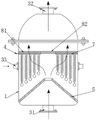
FIG. 1 is a schematic front view of the present invention;
FIG. 2 is a schematic structural view of a cross section of the present invention;
FIG. 3 is a schematic three-dimensional structure of the dust-absorbing cord fabric of the present invention;
FIG. 4 is a schematic cross-sectional view of a dust-absorbing cord according to the present invention;
FIG. 5 is a schematic view of the structure at A in FIG. 4;
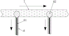
FIG. 6 is a schematic structural view of the joint between the water network pipe and the dust-absorbing curtain cloth.
The reference numbers in the figures illustrate:
the device comprises a device body 1, a transparent sealing door 2, an air inlet 31, an air outlet 32, an air charging port 33, a water inlet pipe 4, a convex air hood 5, a dust collection cloth piece 6, a longitudinal water guide line 61, a water absorption ball 62, a water through net pipe 7, an air filtering layer 81, a sealing layer 82, a counterweight ball 9 and a dust collection wire 10.
Detailed Description
The drawings in the embodiments of the invention will be combined; the technical scheme in the embodiment of the invention is clearly and completely described; obviously; the described embodiments are only some of the embodiments of the invention; but not all embodiments, are based on the embodiments of the invention; all other embodiments obtained by a person skilled in the art without making any inventive step; all fall within the scope of protection of the present invention.
In the description of the present invention, it should be noted that the terms "upper", "lower", "inner", "outer", "top/bottom", and the like indicate orientations or positional relationships based on those shown in the drawings, and are only for convenience of description and simplification of description, but do not indicate or imply that the referred device or element must have a specific orientation, be constructed in a specific orientation, and be operated, and thus should not be construed as limiting the present invention. Furthermore, the terms "first" and "second" are used for descriptive purposes only and are not to be construed as indicating or implying relative importance.
In the description of the present invention, it should be noted that, unless otherwise explicitly specified or limited, the terms "mounted," "disposed," "sleeved/connected," "connected," and the like are to be construed broadly, e.g., "connected," which may be fixedly connected, detachably connected, or integrally connected; can be mechanically or electrically connected; they may be connected directly or indirectly through intervening media, or they may be interconnected between two elements. The specific meanings of the above terms in the present invention can be understood in specific cases to those skilled in the art.
Example 1:
referring to fig. 1, a dust removing device for flue gas treatment comprises a device body 1, a transparent sealing door 2 is installed at the outer end of the device body 1, an air outlet 32 and an air inlet 31 are fixedly connected to the upper end and the lower end of the device body 1 respectively, and the air inlet 31 and the air outlet 32 are communicated with the device body 1.
Referring to fig. 2, a raised air hood 5 is fixedly connected to the inner bottom end of the device body 1, the cross section of the raised air hood 5 is in a shape of a parallel trapezoid which is bilaterally symmetrical, and the raised air hood 5 is of a solid structure, so that the raised air hood 5 is integrally raised, a space enclosed between the outer surface of the raised air hood 5 and the device body 1 can be prevented from being blown by smoke, and dust of larger particles falling from the dust collection curtain cloth is effectively prevented from being blown by the smoke; the device body 1 is internally clamped with a semi-through filter plate, the semi-through filter plate comprises an air filtering layer 81 and a sealing layer 82 fixedly embedded in the middle of the air filtering layer 81, the sealing layer 82 is positioned right above the opening part of the raised air hood 5, the air filtering layer 81 is of a porous structure, the sealing layer 82 is of a solid structure, so that smoke cannot overflow from the sealing layer 82 right opposite to the air filtering layer when the smoke is introduced, the running direction of the smoke deviates outwards and overflows from the air filtering layer 81, and most of smoke can effectively pass through the dust collection curtain cloth, the lower end of the semi-through filter plate is fixedly connected with a water network pipe 7, the outer end of the device body 1 is fixedly connected with a water inlet pipe 4, the water inlet pipe 4 fixedly penetrates through the device body 1 and is communicated with the water network pipe 7, the left outer end and the right outer end of the device body 1 are fixedly connected with an inflation inlet 33, the inflation inlet 33 is communicated with the interior of the device body 1, and the opening part of the inflation inlet 33 is opposite to the dust collection curtain cloth;
the lower end of the water pipe network 7 is fixedly connected with a plurality of dust absorption cord fabrics, the dust absorption cord fabrics are positioned on the outer side above the opening part of the convex air hood 5, the length of the dust absorption cord fabrics is gradually increased from the middle part to the outside, and the lower end part of the dust absorption cord fabric is positioned above the solid part of the convex air hood 5 and is not contacted with the convex air hood 5, so that the area of the dust absorption cord fabric is gradually increased from the middle part to the outside, and the absorption efficiency of the dust absorption cord fabric on small particles in smoke is higher.
Referring to fig. 3, the dust-absorbing cord fabric comprises a dust-absorbing cloth 6 fixedly connected with the lower end of a water inlet pipe 4, a plurality of longitudinal water guide lines 61 fixedly embedded in the dust-absorbing cloth 6, and water-absorbing balls 62 fixedly connected with the upper ends of the longitudinal water guide lines 61, referring to fig. 6, the water-absorbing balls 62 fixedly penetrate through the water network pipe 7 and extend into the water network pipe 7, referring to fig. 4-5, the dust-absorbing cloth 6 is a double-layer net structure, the permeability of the dust-absorbing cloth 6 is correspondingly good under the condition of good adsorptivity of the dust-absorbing cloth 6, when inert gas is introduced into the device body 1 through the inflation inlet 33, the air flow barrier property of the dust-absorbing cloth 6 to the inert gas is small, the effect of scattering the transverse air flow to the smoke gas is better, and the efficient dust absorption is effectively ensured, after a large amount of small dust particles is absorbed, when the dust-absorbing cord fabric is greatly influenced by the transverse air flow through the transparent sealing door 2, stopping the introduction of the smoke, increasing the introduction speed of the inert gas at the inflation inlet 33, enabling the transverse airflow to enable a plurality of dust-absorbing curtain cloth to float and rub with each other, enabling the surface of the dust-absorbing curtain cloth to absorb the dry particles to fall off, and cleaning the falling dust through the transparent sealing door 2, wherein the longitudinal guide assembly line 61 is positioned between the double-layer nets, the dust-absorbing cloth piece 6 is woven by a water-absorbing material, the longitudinal guide assembly line 61 can absorb the clear water introduced into the water-passing net pipe 7 through the water inlet pipe 4 into the dust-absorbing curtain cloth and disperse the clear water to the surface of the dust-absorbing cloth piece 6, so that the surface of the dust-absorbing cloth piece 6 is wet, and the absorption effect of the dust-absorbing.
Dust absorption cloth 6 a plurality of counter weight balls of lower extreme fixedly connected with 9, the coating of counter weight ball 9 surface has the water to send the colour layer, when dust absorption cloth 6 adsorbs the clear water in the below, water can be infected with counter weight ball 9 surface, make its surface discolour, be convenient for remind the moist condition on the staff dust absorption cloth 6, thereby be convenient for the staff in time lets in the flue gas from air inlet 31, carry out the processing of flue gas, thereby effectively guarantee the treatment effeciency of flue gas, 6 outer fixed surface of dust absorption cloth is connected with a plurality of evenly distributed's dust absorption silk 10, dust absorption silk 10 is made for absorbent hard material, effectively increase the adsorption area of 6 surfaces of dust absorption cloth to the middle and small granule dust in the smoke and dust, show the treatment effeciency of improvement to the flue gas.
A dust removal device for flue gas treatment comprises the following steps:
s1, firstly, injecting clean water into the water passing pipe network 7 through the water inlet pipe 4 until the color of the counterweight ball 9 is observed to change through the transparent sealing door 2, and starting to introduce smoke into the device body 1 from the air inlet 31;
s2, introducing inert gas into the device body 1 through the inflation inlet 33, and forming transverse airflow in the device body 1, so that on one hand, the dust absorption curtain cloth is blown to enable the dust absorption curtain cloth to be more fully contacted with smoke, on the other hand, the transverse airflow can effectively disperse rising smoke, the time length of the smoke in the dust absorption curtain cloth is prolonged, small particle dust in the smoke is more fully adhered to the dust absorption curtain cloth, the contact amount of the small particle dust in the smoke and the semi-through filter plate is effectively reduced, the condition frequency of the filter plate is obviously reduced, and the influence on the smoke treatment efficiency is reduced;
and S3, the smoke passes through the half-through filter plate and then is discharged towards the exhaust port 32.
Through the arrangement of the dust absorption curtain cloth, small particle dust in smoke can be adsorbed before the smoke reaches the semi-through filter plate, the contact amount of the small particle dust in the smoke and the semi-through filter plate is effectively reduced, the condition frequency of the filter plate is obviously reduced, and the influence on the smoke treatment efficiency is reduced.
The above; but are merely preferred embodiments of the invention; the scope of the invention is not limited thereto; any person skilled in the art is within the technical scope of the present disclosure; the technical scheme and the improved concept of the invention are equally replaced or changed; are intended to be covered by the scope of the present invention.

Claims (7)

1. The utility model provides a dust collector for flue gas treatment, includes device body (1), transparent sealing door (2) are installed to device body (1) outer end, both ends are fixedly connected with gas vent (32) and air inlet (31) respectively about device body (1), air inlet (31) and gas vent (32) all communicate with each other its characterized in that with device body (1): the device is characterized in that a protruding air hood (5) is fixedly connected to the inner bottom end of the device body (1), a half-through filter plate is clamped inside the device body (1), a water pipe network (7) is fixedly connected to the lower end of the half-through filter plate, a water inlet pipe (4) is fixedly connected to the outer end of the device body (1), the water inlet pipe (4) fixedly penetrates through the device body (1) and is communicated with the water pipe network (7), a plurality of dust-absorbing curtain cloths are fixedly connected to the lower end of the water pipe network (7) and are located on the outer side above the opening of the protruding air hood (5), inflation ports (33) are fixedly connected to the left outer end and the right outer end of the device body (1), the inflation ports (33) are communicated with the inside of the device body (1), the opening of the inflation ports (33) is opposite to the dust-absorbing curtain cloths, and the dust-absorbing curtain cloths comprise dust-absorbing cloth sheets (6) fixedly connected to the lower end of the water inlet pipe (4), A plurality of fixed vertical guide waterline (61) and the ball (62) of absorbing of fixed connection in vertical guide waterline (61) upper end of inlaying in dust absorption cloth piece (6), it is fixed to run through in water network management pipe (7) and extend to water network management pipe (7) to absorb water ball (62), dust absorption cloth piece (6) are double-deck netted structure, vertical guide waterline (61) are located between the double-deck net, and dust absorption cloth piece (6) weave for absorbent material and form, a plurality of counter weight balls (9) of dust absorption cloth piece (6) lower extreme fixedly connected with, the coating of counter weight ball (9) surface has water to send the discoloration layer.
2. The dust removing device for flue gas treatment according to claim 1, wherein: the cross section of the convex gas hood (5) is in a shape of a parallel trapezoid with bilateral symmetry, and the convex gas hood (5) is of a solid structure.
3. The dust removing device for flue gas treatment according to claim 2, wherein: half logical filter plate includes gas filtering layer (81) and fixed seal layer (82) of inlaying in gas filtering layer (81) middle part, seal layer (82) are located protruding gas hood (5) oral area directly over.
4. The dust removing device for flue gas treatment according to claim 3, wherein: the gas filtering layer (81) is of a porous structure, and the sealing layer (82) is of a solid structure.
5. The dust removing device for flue gas treatment according to claim 2, wherein: the length of the dust absorption curtain cloth is gradually longer from the middle part to the outside, and the lower end part of the dust absorption curtain cloth is positioned above the solid part of the convex air hood (5) and is not contacted with the convex air hood (5).
6. The dust removing device for flue gas treatment according to claim 1, wherein: the outer surface of the dust collection cloth piece (6) is fixedly connected with a plurality of dust collection wires (10) which are uniformly distributed, and the dust collection wires (10) are made of water-absorbing hard materials.
7. The dust removing device for flue gas treatment according to any one of claims 1 to 6, wherein: the dust removal method comprises the following steps:
s1, firstly, injecting clear water into the water passing pipe network (7) through the water inlet pipe (4) until the color of the counterweight ball (9) is observed to change through the transparent sealing door (2), and introducing smoke into the device body (1) from the air inlet (31);
s2, introducing inert gas into the device body (1) through the inflation inlet (33), and forming transverse airflow in the device body (1), so that on one hand, the dust absorption curtain cloth is blown to enable the dust absorption curtain cloth to be more fully contacted with smoke, on the other hand, the transverse airflow can effectively disperse rising smoke, the shuttle time of the smoke in the dust absorption curtain cloth is prolonged, and small-particle dust in the smoke is more fully adhered to the dust absorption curtain cloth;
and S3, the smoke passes through the half-through filter plate and then is discharged towards the exhaust port (32).
CN202110344173.5A 2021-03-31 2021-03-31 Dust removal device for flue gas treatment and dust removal method thereof Active CN112717618B (en)

Priority Applications (1)

Application Number Priority Date Filing Date Title
CN202110344173.5A CN112717618B (en) 2021-03-31 2021-03-31 Dust removal device for flue gas treatment and dust removal method thereof

Applications Claiming Priority (1)

Application Number Priority Date Filing Date Title
CN202110344173.5A CN112717618B (en) 2021-03-31 2021-03-31 Dust removal device for flue gas treatment and dust removal method thereof

Publications (2)

Publication Number Publication Date
CN112717618A CN112717618A (en) 2021-04-30
CN112717618B true CN112717618B (en) 2021-07-23

Family

ID=75596171

Family Applications (1)

Application Number Title Priority Date Filing Date
CN202110344173.5A Active CN112717618B (en) 2021-03-31 2021-03-31 Dust removal device for flue gas treatment and dust removal method thereof

Country Status (1)

Country Link
CN (1) CN112717618B (en)

Citations (6)

* Cited by examiner, † Cited by third party
Publication number Priority date Publication date Assignee Title
EP0134297A2 (en) * 1983-07-16 1985-03-20 Intensiv-Filter GmbH & Co KG Wet filter for separating solids and adsorbing toxic gases and odorous substances
KR20050015466A (en) * 2003-08-06 2005-02-21 한국기계연구원 Air cleaner with self cleaning function
CN202427310U (en) * 2011-12-30 2012-09-12 河北卓亿线路器材有限公司 Water curtain type dust and waste gas treatment device
CN104027991A (en) * 2014-06-20 2014-09-10 张可然 Convection type spray dryer
CN106731371A (en) * 2016-11-18 2017-05-31 江苏智石科技有限公司 A kind of air cleaner
CN109402852A (en) * 2017-08-17 2019-03-01 泰州博远科技咨询有限公司 A kind of dust protected water spray woven fabric machine

Patent Citations (6)

* Cited by examiner, † Cited by third party
Publication number Priority date Publication date Assignee Title
EP0134297A2 (en) * 1983-07-16 1985-03-20 Intensiv-Filter GmbH & Co KG Wet filter for separating solids and adsorbing toxic gases and odorous substances
KR20050015466A (en) * 2003-08-06 2005-02-21 한국기계연구원 Air cleaner with self cleaning function
CN202427310U (en) * 2011-12-30 2012-09-12 河北卓亿线路器材有限公司 Water curtain type dust and waste gas treatment device
CN104027991A (en) * 2014-06-20 2014-09-10 张可然 Convection type spray dryer
CN106731371A (en) * 2016-11-18 2017-05-31 江苏智石科技有限公司 A kind of air cleaner
CN109402852A (en) * 2017-08-17 2019-03-01 泰州博远科技咨询有限公司 A kind of dust protected water spray woven fabric machine

Also Published As

Publication number Publication date
CN112717618A (en) 2021-04-30

Similar Documents

Publication Publication Date Title
CN105951412A (en) Nap absorber
CN210645712U (en) Multistage bag collector of industry
CN107676832A (en) A kind of replaceable cleaning device of lampblack absorber
CN107321150B (en) A solid-state flue gas treatment device for chemical laboratories
CN205287996U (en) Microcirculation industrial dust clarifier
CN112717618A (en) Dust removal device for flue gas treatment and dust removal method thereof
CN204786864U (en) Kitchen air purifier of family
CN208018386U (en) A kind of industrial waste gas dedusting equipment
CN206965376U (en) A kind of sand prevention is dust-proof to use airstrainer
CN214132209U (en) Air dryer device capable of removing dust
CN213433669U (en) Waste gas treatment and equipment for dust removal
CN105688545B (en) Ball film dust-remover
CN206621912U (en) A kind of exhaust dust device with bag in flue gas purification system
CN206560735U (en) A kind of automobile air conditioner filter with sealing device
CN206449771U (en) A kind of Novel air purification device
CN108543391A (en) A kind of novel ecological antibacterial air-purification filter device and use technique
CN208742224U (en) A kind of novel ecological antibacterial air-purification filter device
CN108716734A (en) A kind of device of formaldehyde adsorption
CN209501959U (en) A kind of electrostatic precipitation flue dust pretreatment unit
CN210544136U (en) Car light glass processing piece collection device
CN207137661U (en) A kind of solid-state flue gas processing device for Chemical Engineering Laboratory
CN120155010B (en) A dust and toxic substance synergistic high-efficiency cartridge dust collector and its application method
CN209317330U (en) A kind of clarifying smoke all-in-one machine
CN221999304U (en) Tail gas treatment device for mortar fineness negative pressure screen analysis instrument
CN205948549U (en) Pneumatic whirl parallel combination PM2. 5 removing device

Legal Events

Date Code Title Description
PB01 Publication
PB01 Publication
SE01 Entry into force of request for substantive examination
TA01 Transfer of patent application right

Effective date of registration: 20210618

Address after: 421100 Yunji Industrial Park, Yunji Avenue, Yunji Town, Hengnan County, Hengyang City, Hunan Province

Applicant after: Hunan Hongtu Intelligent Technology Co.,Ltd.

Address before: 410000 room 1201, building C4, luguyuyuan, No.27 Wenxuan Road, high tech Development Zone, Changsha City, Hunan Province

Applicant before: Lugu Jinshi Environmental Protection Engineering Technology Co.,Ltd.

GR01 Patent grant
GR01 Patent grant
TR01 Transfer of patent right

Effective date of registration: 20210908

Address after: 410000 room 1201, building C4, luguyuyuan, No.27 Wenxuan Road, high tech Development Zone, Changsha City, Hunan Province

Patentee after: Lugu Jinshi Environmental Protection Engineering Technology Co.,Ltd.

Address before: 421100 Yunji Industrial Park, Yunji Avenue, Yunji Town, Hengnan County, Hengyang City, Hunan Province

Patentee before: Hunan Hongtu Intelligent Technology Co.,Ltd.