Intelligent robot track capable of being deployed rapidly
Technical Field
The invention relates to the technical field of intelligent robot tracks, in particular to an intelligent robot track capable of being deployed quickly.
Background
An intelligent mobile robot is a comprehensive system integrating multiple functions of environment perception, dynamic decision and planning, behavior control and execution and the like. The method integrates the research results of multiple subjects such as sensor technology, information processing, electronic engineering, computer engineering, automatic control engineering, artificial intelligence and the like, represents the highest achievement of mechanical-electrical integration, and is one of the most active fields of scientific and technical development at present. With the continuous improvement of the performance of the robot, the application range of the mobile robot is greatly expanded, and the mobile robot is widely applied to industries such as industry, agriculture, medical treatment, service and the like, and is well applied to harmful and dangerous occasions such as the fields of urban safety, national defense, space detection and the like.
The movable shooting robot can be used when movie shooting is carried out, the moving track of the robot needs to be erected at different places, the erecting process is troublesome, meanwhile, the smooth track is long normally when the robot moves for ensuring that the robot is inconvenient to transport, and meanwhile, the shooting quality of the robot in the moving process can be influenced if foreign matters exist on the track.
Disclosure of Invention
Aiming at the problems in the prior art, the invention provides an intelligent robot track capable of being deployed rapidly.
The technical scheme adopted by the invention for solving the technical problems is as follows: the utility model provides an intelligent robot track that can deploy fast, includes mount pad, dismouting structure, regulation structure, bearing structure, clean structure and drive structure for the top side of the mount pad that supports intelligent robot is equipped with and is used for wholly carrying out quick assembly disassembly to the slide rail dismouting structure, be equipped with on the mount pad and be used for adjusting the distance between the guide rail adjust the structure, the bottom side of mount pad is equipped with and is used for carrying out the whole bearing structure that supports of guide rail, mount pad top side is equipped with and is used for carrying out the cleanness to the guide rail clean structure, the inside promotion that is equipped with of clean structure clean effect drive structure.
Specifically, the dismouting structure includes guide rail body, connecting block, first block pole, draw-in groove and first spring, adjacent two parallel between the mount pad is equipped with two the guide rail body, the tip of guide rail body with sliding connection between the connecting block, the inside sliding connection of connecting block has first block pole, the tip of guide rail body has been seted up the draw-in groove, the one end of first block pole is passed through the draw-in groove with the guide rail body block mutually with, the top of first block pole with fixedly connected with between the connecting block first spring.
It is specific, adjust the structure and include first regulation pole, worm wheel, first pivot, first gear and first rack, the inboard of mount pad is equipped with two relatively first rack, the inboard of connecting block is rotated and is connected with two first pivot, the one end fixedly connected with of first pivot first gear, first gear and homonymy first rack meshes mutually, the top fixedly connected with of first pivot the worm wheel, two the meshing has between the worm wheel the worm, the middle part fixedly connected with of worm the first regulation pole, the both ends of first regulation pole respectively with rotate between the mount pad and connect.
Specifically, the supporting structure comprises a first supporting rod, a second supporting rod, a sliding block, a second clamping rod, a second spring, a third spring, a touch block, a hook rod and a slot, two sliding blocks are respectively connected to two ends of the bottom side of the mounting seat in a sliding manner, the bottom ends of the two sliding blocks on the same side are respectively connected with the first supporting rod and the second supporting rod in a rotating manner, the first supporting rod and the second supporting rod are rotatably connected in an X-shaped manner, the touch block is abutted against one side of the sliding block, the third spring is fixedly connected between the other side of the touch block and the mounting seat, the hook rod is fixedly connected to the other side of the touch block, the slot is formed in one side of the sliding block of the mounting seat, the second clamping rod is arranged between the two touch blocks, and the second clamping rod is rotatably connected with the mounting seat, and the second spring is fixedly connected between the top end of the second clamping rod and the mounting seat.
Specifically, the cleaning structure comprises push blocks, connecting rods, sliding grooves, fourth springs, pulleys, a cleaning brush, an extrusion block, a fifth spring and a second rotating shaft, the sliding grooves are formed in the side surfaces of the guide rail body and the connecting block, the pulleys are rotatably connected to the side surfaces of the push blocks, the pulleys arranged on the side surfaces of the push blocks are slidably connected with the guide rail body through the sliding grooves arranged on the same side, the connecting rods are slidably connected between the two push blocks, the fourth springs are fixedly connected between the two ends of the connecting rods and the push blocks on the same side respectively, the second rotating shaft is rotatably connected to the inner sides of the push blocks, the extrusion block is slidably connected to the bottom end of the second rotating shaft, the fifth springs are fixedly connected between the extrusion block and the second rotating shaft, and the cleaning brush is fixedly connected to the bottom side of the extrusion block, the cleaning brush is abutted against the top side of the guide rail body on the same side.
Specifically, the drive structure includes second rack, third pivot, second gear, third gear and fourth gear, the guide rail body with the equal fixedly connected with in side of connecting block the second rack, the inboard rotation of ejector pad is connected with the third pivot, third pivot fixedly connected with have the second gear, the second gear with the second rack meshes mutually, the side of second gear is equipped with the third gear, the third gear with third pivot fixed connection, fixedly connected with in the second pivot the fourth gear, the fourth gear with perpendicular meshing between the third gear.
The invention has the beneficial effects that:
(1) according to the intelligent robot track capable of being deployed quickly, the rapid disassembly and assembly of the installation slide rail of the robot can be realized through the disassembly and assembly structure, so that the guide rail is deployed quickly and transported conveniently, and the space between the guide rails can be adjusted through the adjusting structure, so that the intelligent robot track is suitable for the moving requirements of different camera robots; namely: when the installation of carrying out the guide rail, at first need insert one side of connecting block with the tip of guide rail body, make the tip of guide rail body align with the lateral surface of connecting block, guarantee the gliding smoothness nature of robot, the inboard of connecting block is equipped with first block pole, first block pole can block mutually with the draw-in groove of this tip of guide rail when guide rail body inlays completely with, thereby fix between connecting block and the guide rail body, the user then only need when needing to demolish the exposure part that the first block pole that lies in the connecting block side of sliding can, to the robot of different specifications, the user can be through rotating first regulation pole, because the worm reverse setting that first regulation pole both sides set up, make along with the rotation of first regulation pole can drive first pivot through the worm wheel and begin to rotate, thereby promote two connecting blocks and remove in opposite directions or relatively, and the meshing between the first gear of first pivot bottom side and the first rack makes the removal of connecting block more stable and flow Smoothly, the function of changing the distance between the parallel guide rail bodies is achieved.
(2) According to the intelligent robot track capable of being deployed quickly, the guide rail can be stably supported through the supporting structure, meanwhile, the supporting rod is convenient to disassemble and assemble, and the guide rail is convenient to install; namely: when carrying out arranging of guide rail, the bottom side of mount pad is equipped with first bracing piece and the second bracing piece that is "X" form setting, two sets of bracing pieces can play stable supporting role to the mount pad, and for convenient transportation, the user is when carrying out the dismouting, can rotate first bracing piece and second bracing piece, make to take place to slide between the slider that the bottom set up and the mount pad, slide to slot position until the slider, the user can directly take out slider and first bracing piece and second bracing piece this moment, simultaneously along with the removal of slider, conflict piece can be promoted to the inboard inconsistent with the mount pad, the tip of the hook bar of conflict piece side can take place the block with second block pole side this moment, thereby the position of conflict piece is fixed when to this, make things convenient for the slider to install.
(3) According to the intelligent robot track capable of being deployed quickly, foreign matters on the surface of the guide rail can be removed through the cleaning structure, the stability of the camera robot in the moving process is ensured, the robot is prevented from bumping in the moving process, the cleaning structure can be driven through the driving structure, and therefore the foreign matters on the slide rail can be swept; namely: the top side of the guide rail body is provided with the push block, the connecting rod and the fourth spring between the two push blocks can ensure the attaching degree between the push block and the guide rail body, foreign matters on the surface of the guide rail body can be timely cleared away through the cleaning brush arranged inside by sliding the push block to avoid obstructing the normal and stable movement of the camera robot, the top side of the cleaning brush is provided with the fifth spring to ensure that the cleaning brush can be tightly abutted against the top side of the guide rail body to play a good cleaning effect, in order to timely clear away the foreign matters, the side surfaces of the guide rail body and the connecting block are also provided with the second rack which is meshed with the second gear on the inner side of the push block, along with the sliding of the push block, the third rotating shaft can start to rotate, then the second rotating shaft is driven to start to rotate through the transmission effect of the third gear and the fourth gear, so that the cleaning brush can rotate in the sliding process, the foreign bodies are timely swept away from the surface of the guide rail body, and the stable movement of the robot is guaranteed.
Drawings
The invention is further illustrated with reference to the following figures and examples.
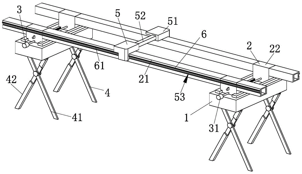
Fig. 1 is a schematic structural diagram of an overall structure of a preferred embodiment of a rapidly deployable intelligent robot track provided in the present invention;
FIG. 2 is a schematic view of the connection structure between the disassembly and assembly structure and the support structure shown in FIG. 1;
FIG. 3 is an enlarged view of the structure A shown in FIG. 2;
FIG. 4 is an enlarged view of the structure B shown in FIG. 2;
FIG. 5 is a schematic view of a coupling structure of the disassembling structure and the cleaning structure shown in FIG. 1;
fig. 6 is a schematic view of a coupling structure of the cleaning structure and the driving structure shown in fig. 1.
In the figure: 1. a mounting seat, 2, a dismounting structure, 21, a guide rail body, 22, a connecting block, 23, a first clamping rod, 24, a clamping groove, 25, a first spring, 3, an adjusting structure, 31, a first adjusting rod, 32, a worm, 33, a worm wheel, 34, a first rotating shaft, 35, a first gear, 36, a first rack, 4, a supporting structure, 41, a first supporting rod, 42, a second supporting rod, 43, a sliding block, 44, a second clamping rod, 45, a second spring, 46, a third spring, 47, an abutting block, 48, a second clamping rod, 49, a slot, 5, a cleaning structure, 51, a pushing block, 52, a connecting rod, 53, a sliding groove, 54, a fourth spring, 55, a pulley, 56, a cleaning brush, 57, an extrusion block, 58, a fifth spring, 59, a second rotating shaft, 6, a driving structure, 61, a second rack, 62, a third rotating shaft, 63, a second gear, 64, a third gear, 65. a fourth gear.
Detailed Description
In order to make the technical means, the creation characteristics, the achievement purposes and the effects of the invention easy to understand, the invention is further described with the specific embodiments.
As shown in fig. 1-6, the intelligent robot rail capable of being deployed quickly according to the present invention includes an installation base 1, a dismounting structure 2, an adjusting structure 3, a supporting structure 4, a cleaning structure 5, and a driving structure 6, where the dismounting structure 2 for quickly dismounting and mounting the entire slide rail is disposed on the top side of the installation base 1 for supporting the intelligent robot, the adjusting structure 3 for adjusting the distance between the guide rails is disposed on the installation base 1, the supporting structure 4 for supporting the entire guide rail is disposed on the bottom side of the installation base 1, the cleaning structure 5 for cleaning the guide rail is disposed on the top side of the installation base 1, and the driving structure 6 for improving the cleaning effect of the cleaning structure 5 is disposed inside the cleaning structure 5.
Specifically, the dismounting structure 2 includes a guide rail body 21, a connecting block 22, a first engaging rod 23, a locking groove 24 and a first spring 25, two adjacent guide rail bodies 21 are arranged in parallel between the two mounting seats 1, an end of each guide rail body 21 is slidably connected with the connecting block 22, the first engaging rod 23 is slidably connected inside the connecting block 22, the locking groove 24 is formed in an end of each guide rail body 21, one end of each first engaging rod 23 is engaged with the corresponding guide rail body 21 through the locking groove 24, the first spring 25 is fixedly connected between a top end of each first engaging rod 23 and the corresponding connecting block 22, when the guide rail is mounted, the end of each guide rail body 21 needs to be inserted into one side of the corresponding connecting block 22, so that the end of each guide rail body 21 is aligned with an outer side of the corresponding connecting block 22, guarantee the gliding fluency of robot, the inboard of connecting block 22 is equipped with first block pole 23, first block pole 23 can be in when guide rail body 21 imbeds completely with guide rail body 21 tip draw-in groove 24 block mutually with, thereby will connecting block 22 with fix between the guide rail body 21, the user then only need slide when needing to demolish to be located the connecting block 21 side the exposure part of first block pole 23 can.
Specifically, the adjusting structure 3 includes a first adjusting rod 31, a worm 32, a worm wheel 33, a first rotating shaft 34, a first gear 35 and a first rack 36, two first racks 36 are oppositely disposed on the inner side of the mounting base 1, two first rotating shafts 34 are rotatably connected to the inner side of the connecting block 22, one end of each first rotating shaft 34 is fixedly connected with the first gear 35, the first gear 35 is engaged with the first rack 36 on the same side, the top end of each first rotating shaft 34 is fixedly connected with the worm wheel 33, the worm 32 is engaged between the two worm wheels 33, the middle of the worm 32 is fixedly connected with the first adjusting rod 31, two ends of the first adjusting rod 31 are rotatably connected with the mounting base 1, for robots of different specifications, a user can rotate the first adjusting rod 31, because the worms 32 disposed on two sides of the first adjusting rod 31 are reversely disposed, so that the first adjusting rod 31 can rotate to drive the first rotating shaft 34 to rotate through the worm gear 33, thereby pushing the two connecting blocks 22 to move towards or towards each other, and the engagement between the first gear 35 at the bottom side of the first rotating shaft 34 and the first rack 36 makes the movement of the connecting blocks 22 more stable and smooth, achieving the function of changing the distance between the parallel guide rail bodies 21.
Specifically, the supporting structure 4 includes a first supporting rod 41, a second supporting rod 42, a sliding block 43, a second engaging rod 44, a second spring 45, a third spring 46, a contact block 47, a hook rod 48 and a slot 49, two sliding blocks 43 are respectively connected to two ends of the bottom side of the mounting base 1 in a sliding manner, the bottom ends of the two sliding blocks 43 on the same side are respectively connected to the first supporting rod 41 and the second supporting rod 42 in a rotating manner, the first supporting rod 41 and the second supporting rod 42 are connected in an X-shaped rotating manner, the contact block 47 is abutted to one side of the sliding block 43, the third spring 46 is fixedly connected between the other side of the contact block 47 and the mounting base 1, the hook rod 48 is further fixedly connected to the other side of the contact block 47, the slot 49 is formed in one side of the sliding block 43 of the mounting base 1, the second engaging rod 44 is arranged between the two contact blocks 47, the second engaging rod 44 is rotatably connected to the mounting base 1, and the second spring 45 is fixedly connected between the top end of the second engaging rod 44 and the mounting base 1, when the guide rail is arranged, the first support rod 41 and the second support rod 42 are arranged in an "X" shape at the bottom side of the mounting base 1, two sets of support rods can stably support the mounting base 1, and when the user carries out the dismounting, the user can rotate the first support rod 41 and the second support rod 42 to make the slider 43 arranged at the bottom end slide with the mounting base 1 until the slider 43 slides to the slot 49 position, at this time, the user can directly take out the slider 43 and the first support rod 41 and the second support rod 42, and simultaneously along with the movement of the slider 43, the contact block 47 is pushed to abut against the inner side of the mounting base 1, and at this time, the end of the hook rod 48 on the side surface of the contact block 47 is engaged with the side surface of the second engaging rod 44, so that the position of the contact block 47 is fixed, and the slider 43 is convenient to mount.
Specifically, the cleaning structure 5 includes a push block 51, a connecting rod 52, a sliding groove 53, a fourth spring 54, a pulley 55, a cleaning brush 56, an extrusion block 57, a fifth spring 58 and a second rotating shaft 59, the sliding groove 53 is formed on the side surfaces of the guide rail body 21 and the connecting block 22, the pulley 55 is rotatably connected to the side surface of the push block 51, the pulley 55 arranged on the side surface of the push block 51 is slidably connected to the guide rail body 21 through the sliding groove 53 arranged on the same side, the connecting rod 52 is slidably connected between the two push blocks 51, the fourth spring 54 is fixedly connected between the two ends of the connecting rod 52 and the push block 51 on the same side, the second rotating shaft 59 is rotatably connected to the inner side of the push block 51, the extrusion block 57 is slidably connected to the bottom end of the second rotating shaft 59, and the fifth spring 58 is fixedly connected between the extrusion block 57 and the second rotating shaft 59, the bottom side fixedly connected with of extrusion piece 57 clean brush 56, clean brush 56 with the homonymy the top side of guide rail body 21 is inconsistent, is located the top side of guide rail body 21 is equipped with ejector pad 51, two between ejector pad 51 connecting rod 52 and the fourth spring can guarantee ejector pad 51 with the laminating degree between the guide rail body 21, through sliding ejector pad 51, can be through inside setting clean brush 56 carries out timely clearance to the foreign matter on guide rail body 21 surface, avoids hindering camera robot's normal steady movement, and the top side of clean brush 56 is equipped with fifth spring 58 for clean brush 56 can with the top side of guide rail body 21 closely contradicts, plays good clean effect.
Specifically, the driving structure 6 includes a second rack 61, a third rotating shaft 62, a second gear 63, a third gear 64 and a fourth gear 65, the side surfaces of the guide rail body 21 and the connecting block 22 are fixedly connected with the second rack 61, the inner side of the push block 51 is rotatably connected with the third rotating shaft 62, the third rotating shaft 62 is fixedly connected with the second gear 63, the second gear 63 is engaged with the second rack 61, the side surface of the second gear 63 is provided with the third gear 64, the third gear 64 is fixedly connected with the third rotating shaft 62, the second rotating shaft 59 is fixedly connected with the fourth gear 65, the fourth gear 65 is vertically engaged with the third gear 64, in order to timely sweep away foreign matters, the side surfaces of the guide rail body 21 and the connecting block 22 are further provided with the second rack 61, the second rack 61 is meshed with the second gear 62 on the inner side of the push block 51, along with the sliding of the push block 51, the third rotating shaft 63 can rotate, and then the second rotating shaft 62 is driven to rotate by the transmission effect of the third gear 64 and the fourth gear 65, so that the cleaning brush 56 rotates in the sliding process, foreign matters are swept away on the surface of the guide rail body 21 in time, and the smooth movement of the robot is guaranteed.
When the invention is used, when the guide rail is installed, firstly, the end part of the guide rail body 21 needs to be inserted into one side of the connecting block 22, so that the end part of the guide rail body 21 is aligned with the outer side surface of the connecting block 22, and the smoothness of the sliding of the robot is ensured, the inner side of the connecting block 22 is provided with the first clamping rod 23, the first clamping rod 23 can be clamped with the clamping groove 24 at the end part of the guide rail body 21 when the guide rail body 21 is completely embedded, so that the connecting block 22 and the guide rail body 21 are fixed, when the robot needs to be dismounted, a user only needs to slide the exposed part of the first clamping rod 23 positioned on the side surface of the connecting block 21, for robots of different specifications, the user can rotate the first adjusting rod 31, because the worms 32 arranged at the two sides of the first adjusting rod 31 are reversely arranged, so that the first rotating shaft 34 can be driven, thereby pushing the two connecting blocks 22 to move oppositely or relatively, and the engagement between the first gear 35 and the first rack 36 at the bottom side of the first rotating shaft 34 makes the movement of the connecting blocks 22 more stable and smooth, and achieves the function of changing the distance between the parallel guide rail bodies 21, when the guide rails are arranged, the bottom side of the mounting base 1 is provided with the first support rod 41 and the second support rod 42 which are arranged in an "X" shape, two sets of support rods can play a stable supporting role for the mounting base 1, and for convenient transportation, when a user carries out disassembly and assembly, the first support rod 41 and the second support rod 42 can be rotated, so that the sliding between the sliding block 43 arranged at the bottom end and the mounting base 1 occurs, until the sliding block 43 slides to the position of the slot 49, at this time, the user can directly take out the sliding block 43 and the first support rod 41 and the second support rod 42, and simultaneously along with the movement of the sliding block 43, the contact block 47 can be pushed to abut against the inner side of the mounting base 1, at the moment, the end of a hook rod 48 on the side surface of the contact block 47 can be clamped with the side surface of a second clamping rod 44, so that the position of the contact block 47 is fixed at the moment, the sliding block 43 is convenient to mount, a push block 51 is arranged on the top side of the guide rail body 21, a connecting rod 52 and a fourth spring between the two push blocks 51 can ensure the joint degree between the push block 51 and the guide rail body 21, foreign matters on the surface of the guide rail body 21 can be timely cleared through a cleaning brush 56 arranged inside by sliding the push blocks 51, the normal and stable movement of the camera robot is prevented from being hindered, a fifth spring 58 is arranged on the top side of the cleaning brush 56, so that the cleaning brush 56 can be tightly contacted with the top side surface of the guide rail body 21, a good cleaning effect is achieved, in order to timely clear the foreign matters, a second rack 61 is further arranged on the side surfaces of the guide rail body, second rack 61 meshes with the inboard second gear 62 of ejector pad 51 mutually, along with the slip of ejector pad 51, can make third pivot 63 begin to rotate, then drives second pivot 62 through the transmission effect of third gear 64 and fourth gear 65 and begins to rotate for cleaning brush 56 rotates at gliding in-process, sweeps away the timely surface by guide rail body 21 of foreign matter, guarantees the even movement of robot.
It will be evident to those skilled in the art that the invention is not limited to the details of the foregoing illustrative embodiments, and that the present invention may be embodied in other specific forms without departing from the spirit or essential attributes thereof. The present embodiments are therefore to be considered in all respects as illustrative and not restrictive, the scope of the invention being indicated by the appended claims rather than by the foregoing description, and all changes which come within the meaning and range of equivalency of the claims are therefore intended to be embraced therein. Any reference sign in a claim should not be construed as limiting the claim concerned.
Furthermore, it should be understood that although the present description refers to embodiments, not every embodiment may contain only a single embodiment, and such description is for clarity only, and those skilled in the art should integrate the description, and the embodiments may be combined as appropriate to form other embodiments understood by those skilled in the art.