Double-layer three-section guide rail type planar robot with revolute pairs
Technical Field
The invention relates to the technical field of robots, in particular to a double-layer three-section guide rail type plane robot with a revolute pair.
Background
The parallel robot has the characteristics of high rigidity, high bearing capacity, high precision, small motion load, easiness in inverse solution and the like, so that the parallel robot is widely applied to the aspects of motion simulators, virtual axis machine tools, somatosensory simulators, medical equipment, agricultural operation robots and the like.
For the research of the three-degree-of-freedom robot, a lot of scholars do a lot of work. The Yuesheng provides a plane parallel robot experimental device with 3 flexible hinges based on a 3-RRR parallel robot, and the device can enable a motion platform of a mechanism to realize movement along the direction of an axis X, Y and rotation around the direction of an axis Z. Herve successfully synthesizes a three-degree-of-freedom translational parallel robot, such as a 3-RRC parallel robot, based on lie group and lie algebra theory. The Huangzhen provides a comprehensive method of a parallel robot type with less degrees of freedom including a plurality of translational parallel robots with three degrees of freedom based on the principle of a spiral theory. Liqichuan utilizes a spiral theory to carry out symmetrical three-degree-of-freedom parallel robot type synthesis of the system. The peak integrates a plurality of symmetrical and asymmetrical three-freedom-degree translation parallel robots with novel structures based on GF set theory. In 2011, chenfengming et al provides a novel two-translation one-rotation RRR-URR-RR parallel robot, analyzes the motion output characteristics of the mechanism, calculates the degree of freedom, and establishes a positive and negative solution equation of the position of the parallel robot. In 2016, Jurwei et al, university of Changzhou invented a two-translation and one-rotation parallel robot, which realizes two-dimensional translation motion and one-dimensional rotation motion in space by driving a movable platform to move through three actively-driven moving pairs. In 2018, Yanshan university Liyangxi et al propose a two-translation and one-rotation 2RRR-CRR parallel robot, the mechanism only comprises a moving pair and a rotating pair (a cylindrical pair is formed by combining the moving pair and the rotating pair), and most of the mechanism is the rotating pair, so that the mechanism is simple in structure and the axis relation is easy to satisfy.
Although scholars at home and abroad provide more three-degree-of-freedom robot configuration schemes, the planar three-degree-of-freedom robot has different performance requirements in different application fields, so that the robot configuration types with two translational degrees of freedom and one rotational degree of freedom are provided as many as possible, and the method has important significance for the type selection of researchers in the field.
Disclosure of Invention
The invention aims to solve the technical problem that the prior art has the defects, and provides a double-layer three-section guide rail type planar robot with a revolute pair, which is novel in structure and has two translational freedom degrees and one rotational freedom degree.
The scheme is realized by the following technical measures: a double-layer three-section guide rail type planar robot with a revolute pair comprises a fixed platform, a moving platform and three branched chains which are connected between the fixed platform and the moving platform and have the same structure, wherein three sections of planar curve guide rails I are arranged on the fixed platform, the moving platform is fixedly connected with three sections of planar curve guide rails II, each section of planar curve guide rail I is connected with one section of planar curve guide rail II corresponding to the section of planar curve guide rail I through one branched chain, each branched chain comprises a sliding block I, a connecting rod and a sliding block II, the sliding block I is connected with the planar curve guide rails I in a sliding mode, the sliding block I is connected with one end of the connecting rod in a rotating mode through the revolute pair, the other end of the connecting rod is fixedly connected with the sliding block II; the axes of the three revolute pairs are parallel to each other and are perpendicular to a motion plane I of the sliding block I relative to the plane curve guide rail I and a motion plane II of the sliding block II relative to the plane curve guide rail II, and the three revolute pairs are main driving joints or the three sliding blocks I are driving parts; the three sections of plane curve guide rails I are arc-shaped guide rails with different circle centers, and the three sections of plane curve guide rails II are arc-shaped guide rails with different circle centers.
Preferably, the length of the plane curve guide rail I is larger than that of the plane curve guide rail II, and the width of the plane curve guide rail I is larger than that of the plane curve guide rail II.
Preferably, the motion platform is fixedly connected with three sections of plane curve guide rails II through three fixing rods.
Preferably, the three sliding blocks I are in the same plane or parallel planes relative to the movement plane I of the planar curve guide rail I.
Preferably, the three sliding blocks II are in the same plane or parallel planes relative to the motion plane II of the planar curve guide rail II.
Compared with the prior art, the invention has the advantages that: the three-section guide rail structure is simultaneously introduced into the fixed platform and the moving platform and is matched with the revolute pair for use, so that the robot is guaranteed to have the moving characteristics of two translational degrees of freedom and one rotational degree of freedom, the working space can be increased in a specific degree of freedom by independently increasing the length of each section of guide rail, the flexibility of robot design is improved, meanwhile, the three revolute pairs can be used as main driving joints, the three sliding blocks I can also be used as driving parts, and the flexibility of robot driving mode selection is improved.
Therefore, compared with the prior art, the invention has prominent substantive features and remarkable progress, and the beneficial effects of the implementation are also obvious.
Drawings
In order to more clearly illustrate the technical solution of the present invention, the drawings used in the description will be briefly introduced, and it is obvious that the drawings in the following description are only some embodiments of the present invention, and it is obvious for those skilled in the art that other drawings can be obtained based on these drawings without creative efforts.
FIG. 1 is a schematic structural view of the present invention;
FIG. 2 is a first schematic structural view of a fixed platen;
FIG. 3 is a second schematic structural view of the fixing platform;
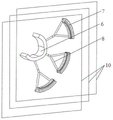
FIG. 4 is a schematic view I of a connection structure of a motion platform and a plane curve guide rail II;
fig. 5 is a schematic view of a connection structure of the motion platform and a plane curve guide rail ii.
In the figure: 1-fixed platform, 1.1-plane curve guide rail I, 2-slide block I, 3-revolute pair, 4-connecting rod, 5-slide block II, 6-moving platform, 7-plane curve guide rail II, 8-fixed rod, 9-moving plane I, 10-moving plane II.
Detailed Description
In order to make the objects, features and advantages of the present invention more obvious and understandable, the technical solutions of the present invention will be clearly and completely described below with reference to specific embodiments and drawings. All other embodiments, which can be derived by a person skilled in the art from the embodiments given herein without making any creative effort, shall fall within the scope of protection of this patent.
As shown in figure 1, a double-layer three-section guide rail type plane robot containing a revolute pair comprises a fixed platform 1, a moving platform 6 and three branched chains with the same structure connected between the fixed platform 1 and the moving platform 6, the fixed platform 1 is provided with three sections of plane curve guide rails I1.1, the moving platform 6 is fixedly connected with three sections of plane curve guide rails II7, each section of plane curve guide rail I1.1 is connected with a section of plane curve guide rail II7 corresponding to the section of plane curve guide rail I through a branched chain, each branched chain comprises a sliding block I2, a connecting rod 4 and a sliding block II 5, one end of the sliding block I2 is connected to the plane curve guide rail I1.1 to realize relative sliding, the other end of the sliding block I2 is connected with one end of the connecting rod 4 through the revolute pair 3, the other end of the connecting rod 4 is fixedly connected with a sliding block II 5, and the sliding block II 5 is connected to a plane curve guide rail II7 to realize relative sliding; the axes of the three revolute pairs 3 are parallel to each other and are perpendicular to a motion plane I9 of the sliding block I2 relative to the plane curve guide rail I1.1 and a motion plane II 10 of the sliding block II 5 relative to the plane curve guide rail II7, and the three revolute pairs 3 are main driving joints or the three sliding blocks I2 are driving links; the three sections of plane curve guide rails I1.1 are arc guide rails with different centers of circles, and the three sections of plane curve guide rails II7 are arc guide rails with different centers of circles. Preferably, the three sections of plane curve guide rails I1.1 are arc guide rails with different centers of circles, and the three sections of plane curve guide rails II7 are arc guide rails with different centers of circles.
The length of plane curve guide rail I1.1 is greater than the length of plane curve guide rail II7, the width of plane curve guide rail I1.1 is greater than the width of plane curve guide rail II 7.
The motion platform 6 is fixedly connected with three sections of plane curve guide rails II7 through three fixing rods 8.
In the technical scheme, the three branched chains with the same structure mean that components contained in the three branched chains and the connection relationship among the components are the same, but the sizes of the same components in the three branched chains can be different.
As shown in fig. 2 to 3, the three sliding blocks I2 are respectively the same plane or parallel planes with respect to the three movement planes I9 of the three-section plane curve guide rail I1.1.
As shown in fig. 4-5, the three sliding blocks II 5 are respectively the same plane or parallel planes with respect to the three motion planes II 10 of the three-section plane curve guide rail II 7.
In the technical scheme, a plane curve guide rail I1.1 is characterized in that a sliding block I2 does plane curve motion along the guide rail as the name implies; the plane curve guide rail II7 is characterized in that the sliding block II 5 does plane curve motion along the guide rail as the name implies.
The embodiments in the present description are described in a progressive manner, each embodiment focuses on differences from other embodiments, and the same and similar parts among the embodiments are referred to each other.
The previous description of the disclosed embodiments is provided to enable any person skilled in the art to make or use the present invention. Various modifications to these embodiments will be readily apparent to those skilled in the art, and the generic principles defined herein may be applied to other embodiments without departing from the spirit or scope of the invention. Thus, the present invention is not intended to be limited to the embodiments shown herein but is to be accorded the widest scope consistent with the principles and novel features and inventive features disclosed herein.