CN1127247C - Termination of coded or uncoded modulation with path-oriented decoder - Google Patents
Termination of coded or uncoded modulation with path-oriented decoder Download PDFInfo
- Publication number
- CN1127247C CN1127247C CN00803586.5A CN00803586A CN1127247C CN 1127247 C CN1127247 C CN 1127247C CN 00803586 A CN00803586 A CN 00803586A CN 1127247 C CN1127247 C CN 1127247C
- Authority
- CN
- China
- Prior art keywords
- signal points
- signal
- constellation
- receiver
- points
- Prior art date
- Legal status (The legal status is an assumption and is not a legal conclusion. Google has not performed a legal analysis and makes no representation as to the accuracy of the status listed.)
- Expired - Fee Related
Links
Images


Classifications
-
- H—ELECTRICITY
- H04—ELECTRIC COMMUNICATION TECHNIQUE
- H04L—TRANSMISSION OF DIGITAL INFORMATION, e.g. TELEGRAPHIC COMMUNICATION
- H04L1/00—Arrangements for detecting or preventing errors in the information received
- H04L1/004—Arrangements for detecting or preventing errors in the information received by using forward error control
- H04L1/0056—Systems characterized by the type of code used
- H04L1/007—Unequal error protection
-
- H—ELECTRICITY
- H04—ELECTRIC COMMUNICATION TECHNIQUE
- H04L—TRANSMISSION OF DIGITAL INFORMATION, e.g. TELEGRAPHIC COMMUNICATION
- H04L1/00—Arrangements for detecting or preventing errors in the information received
- H04L1/0001—Systems modifying transmission characteristics according to link quality, e.g. power backoff
- H04L1/0002—Systems modifying transmission characteristics according to link quality, e.g. power backoff by adapting the transmission rate
- H04L1/0003—Systems modifying transmission characteristics according to link quality, e.g. power backoff by adapting the transmission rate by switching between different modulation schemes
-
- H—ELECTRICITY
- H04—ELECTRIC COMMUNICATION TECHNIQUE
- H04L—TRANSMISSION OF DIGITAL INFORMATION, e.g. TELEGRAPHIC COMMUNICATION
- H04L1/00—Arrangements for detecting or preventing errors in the information received
- H04L1/004—Arrangements for detecting or preventing errors in the information received by using forward error control
- H04L1/0045—Arrangements at the receiver end
- H04L1/0054—Maximum-likelihood or sequential decoding, e.g. Viterbi, Fano, ZJ algorithms
-
- H—ELECTRICITY
- H04—ELECTRIC COMMUNICATION TECHNIQUE
- H04L—TRANSMISSION OF DIGITAL INFORMATION, e.g. TELEGRAPHIC COMMUNICATION
- H04L1/00—Arrangements for detecting or preventing errors in the information received
- H04L1/004—Arrangements for detecting or preventing errors in the information received by using forward error control
- H04L1/0056—Systems characterized by the type of code used
- H04L1/0059—Convolutional codes
- H04L1/006—Trellis-coded modulation
-
- H—ELECTRICITY
- H04—ELECTRIC COMMUNICATION TECHNIQUE
- H04L—TRANSMISSION OF DIGITAL INFORMATION, e.g. TELEGRAPHIC COMMUNICATION
- H04L25/00—Baseband systems
- H04L25/02—Details ; arrangements for supplying electrical power along data transmission lines
- H04L25/03—Shaping networks in transmitter or receiver, e.g. adaptive shaping networks
- H04L25/03006—Arrangements for removing intersymbol interference
- H04L25/03178—Arrangements involving sequence estimation techniques
- H04L25/03203—Trellis search techniques
- H04L25/03235—Trellis search techniques with state-reduction using feedback filtering
-
- H—ELECTRICITY
- H04—ELECTRIC COMMUNICATION TECHNIQUE
- H04L—TRANSMISSION OF DIGITAL INFORMATION, e.g. TELEGRAPHIC COMMUNICATION
- H04L27/00—Modulated-carrier systems
- H04L27/32—Carrier systems characterised by combinations of two or more of the types covered by groups H04L27/02, H04L27/10, H04L27/18 or H04L27/26
- H04L27/34—Amplitude- and phase-modulated carrier systems, e.g. quadrature-amplitude modulated carrier systems
- H04L27/3405—Modifications of the signal space to increase the efficiency of transmission, e.g. reduction of the bit error rate, bandwidth, or average power
- H04L27/3416—Modifications of the signal space to increase the efficiency of transmission, e.g. reduction of the bit error rate, bandwidth, or average power in which the information is carried by both the individual signal points and the subset to which the individual points belong, e.g. using coset coding, lattice coding, or related schemes
- H04L27/3427—Modifications of the signal space to increase the efficiency of transmission, e.g. reduction of the bit error rate, bandwidth, or average power in which the information is carried by both the individual signal points and the subset to which the individual points belong, e.g. using coset coding, lattice coding, or related schemes in which the constellation is the n - fold Cartesian product of a single underlying two-dimensional constellation
- H04L27/3438—Modifications of the signal space to increase the efficiency of transmission, e.g. reduction of the bit error rate, bandwidth, or average power in which the information is carried by both the individual signal points and the subset to which the individual points belong, e.g. using coset coding, lattice coding, or related schemes in which the constellation is the n - fold Cartesian product of a single underlying two-dimensional constellation using an underlying generalised cross constellation
-
- H—ELECTRICITY
- H04—ELECTRIC COMMUNICATION TECHNIQUE
- H04L—TRANSMISSION OF DIGITAL INFORMATION, e.g. TELEGRAPHIC COMMUNICATION
- H04L1/00—Arrangements for detecting or preventing errors in the information received
- H04L1/12—Arrangements for detecting or preventing errors in the information received by using return channel
- H04L1/16—Arrangements for detecting or preventing errors in the information received by using return channel in which the return channel carries supervisory signals, e.g. repetition request signals
- H04L1/18—Automatic repetition systems, e.g. Van Duuren systems
Landscapes
- Engineering & Computer Science (AREA)
- Computer Networks & Wireless Communication (AREA)
- Signal Processing (AREA)
- Power Engineering (AREA)
- Artificial Intelligence (AREA)
- Quality & Reliability (AREA)
- Digital Transmission Methods That Use Modulated Carrier Waves (AREA)
- Error Detection And Correction (AREA)
- Compression, Expansion, Code Conversion, And Decoders (AREA)
- Detection And Prevention Of Errors In Transmission (AREA)
Abstract
Description
技术领域technical field
本发明涉及数据通信,并且在特定实施例中,涉及在出现码间干扰的信道上进行的数据通信。The present invention relates to data communications, and in particular embodiments, to data communications over channels in which intersymbol interference occurs.
发明背景Background of the invention
码间干扰(ISI)信道是由信道中的失真造成的,在一个信令间隔中传输的信号点的信号能量被分散到许多相邻的信令间隔中。分散的能量与相邻间隔中传输的信号点相组合,这样就在那些其他间隔中构成了一个噪声源。当ISI的电平很低时,一个所谓的线性均衡器就能有效的将其减弱。然而,如果ISI很严重,那么就需要使用功能更强的技术。通常这些技术都使用了一个判定反馈均衡器(DFE)。DFE对在给出的被接收信号中的ISI数值进行估算,并将该ISI估算从接收信号中减去,以获取一个ISI被补偿的信号点,从该点作出有关对被发射的信号点识别的判定。Intersymbol Interference (ISI) channels are caused by distortions in the channel where the signal energy of a signal point transmitted in one signaling interval is spread over many adjacent signaling intervals. The scattered energy combines with signal points transmitted in adjacent intervals, thus constituting a noise source in those other intervals. When the ISI level is low, a so-called linear equalizer can effectively reduce it. However, if ISI is severe, then more powerful techniques need to be used. Typically these techniques use a decision feedback equalizer (DFE). The DFE estimates the ISI value in a given received signal and subtracts the ISI estimate from the received signal to obtain an ISI-compensated signal point from which relevant identification of the transmitted signal point is made judgment.
其中一种这样的技术在我于1998年3月27日提交,申请序列号为09/049268,题为“使用精选的接收机网格图的面向路径的解码器”的待审美国专利申请中给出。ISI现象被证明是由于信令间隔中传输的信号点能量的一部分被分散到了相邻信令间隔中所造成的。该份专利申请中所描述的技术使用了一个所谓的面向路径的联合解码器/DFE,它具有一个精选的接收机网格图,来有效地将被分散到其他信令间隔中的信号能量的至少一部分,返回到每个信号点。这就提供了对被称为“变换增益”的抗误码能力的改进。One such technique is described in my pending U.S. Patent Application Serial No. 09/049268, filed March 27, 1998, entitled "Path-Oriented Decoder Using a Selected Receiver Trellis Graph" given in. The phenomenon of ISI is proved to be caused by the fact that a part of the signal point energy transmitted in a signaling interval is dispersed into adjacent signaling intervals. The technique described in this patent application uses a so-called path-oriented joint decoder/DFE with a carefully selected receiver trellis map to efficiently disperse signal energy into other signaling intervals At least part of , returned to each signal point. This provides an improvement in bit error immunity known as "conversion gain".
发明概要Summary of the invention
上述变换增益并没有在任意给定的传输中的最后几个信号点中充分实现。这方面的原因是后续的信令间隔数量较少,而只有通过这些信令间隔才能将被分散的最后几个信号点的信号能量加以集中并返回到相应的信号点。实际上,这个较少的数量在涉及到极为靠后的信号点时,可能会为零。因此对这些末端信号点的解码不如那些变换增益得到确保的信号点可靠。这个问题可以通过传输虚假信号点,人工创建附加的信令间隔而加以克服,由此为实际数据信号点的分散能量提供了一个机会,使之能够如上面所讨论的那样被集中。The conversion gain described above is not fully realized in the last few signal points in any given transmission. The reason for this is that the number of subsequent signaling intervals is small, and only through these signaling intervals can the scattered signal energy of the last few signal points be concentrated and returned to the corresponding signal points. In fact, this small amount may be zero when it comes to very late signal points. The decoding of these end signal points is therefore less reliable than those for which the transformation gain is ensured. This problem can be overcome by transmitting false signal points, artificially creating additional signaling intervals, thereby providing an opportunity for the scattered energy of the actual data signal points to be concentrated as discussed above.
上述技术在一个连续传输的环境中——其中可能传输数百万比特的流量——是切实可行的——因为由此造成的带宽效率上的降低(平均每个信令间隔中有用数据的比特数)是可以忽略不计的。然而,对信号点在离散的分组中传输,分组中包含数目相对较少的信号点(通常是几百个的数量级)的分组传输来说,虚假信号点的导入可能会对带宽效率产生过于巨大的影响。另一方面,不发送虚假信号点意味着对最后不多的几个信号点所进行的解码将不如先前信号点的解码可靠。这在分组传输环境中是非常不利的,因为涉及其他信号点的末端信号点性能将会对总的误码性能施加决定性的影响,即使只有一个信号点的解码出错,通常整个分组都会被标记为出错。The above technique is feasible in a continuous transmission environment - where millions of bits of traffic may be transmitted - because of the resulting loss in bandwidth efficiency (average bits of useful data per signaling interval number) is negligible. However, for packet transmission where signal points are transmitted in discrete packets containing a relatively small number of signal points (usually on the order of hundreds), the introduction of false signal points may have too much impact on bandwidth efficiency. Impact. On the other hand, not sending spurious signal points means that the decoding of the last few signal points will be less reliable than the decoding of the previous signal points. This is very unfavorable in a packet transmission environment, because the performance of the end signal point involving other signal points will exert a decisive influence on the overall bit error performance. Even if only one signal point is decoded incorrectly, usually the entire packet will be marked as error.
本发明针对一种在数据通信环境中使用的技术,其中,按照上面的讨论,信号点流量中的一部分信号点受益于抗误码能力增强的一种特定形式——例如上述的变换增益——而其他信号点则较少从中受益,其中包括一点都不受益。根据本发明的原理,在信号点流量中预定位置出现的,从抗误码能力增强中受益较少的信号点,以这样一种方式被传输,使得它们对抗误码的稳健性至少与从其中受益更多的信号点一样强。这样本发明排除了对例如一个分组传输信令方案的整个误码率性能起决定性影响的末端信号点的上述问题。The present invention is directed to a technique for use in a data communications environment where, as discussed above, a fraction of the signal point traffic benefits from a specific form of error robustness enhancement—such as the above-mentioned conversion gain— Other signal points benefited less from it, including none at all. In accordance with the principles of the present invention, signal points occurring at predetermined positions in the signal point traffic, which would benefit less from enhanced error resistance, are transmitted in such a way that they are at least as robust against bit errors as those from which Benefit from more signal points as strong. The invention thus eliminates the above-mentioned problem of the end signal point which has a decisive influence on the overall bit error rate performance of eg a packet transmission signaling scheme.
在本发明所公开的示范性的分组传输实施例中,分组的末端信号点使用一个信号点星座图来进行传输,该星座图所具有的信号点比那些用于在它们之前的信号点的星座图少,以便末端信号点在信号空间上可以进一步相互远离。结果,可以耐受更多的噪声并且末端信号点的总的误码性能可以不比其他信号点的差。这样,实质上可以为分组传输实现与连续传输相同的总的分组误码率,因为(a)分组中出现较早的信号点受益于转换增益(b)为不受益于转换增益的末端信号点提供了其他形式的增强的抗误码能力。此外,本发明显著地改进了如上所述的使用虚假信号点,而可能引起的带宽效率上的降低。In the exemplary packet transmission embodiment disclosed in the present invention, the terminal signal points of the packet are transmitted using a signal point constellation having more signal points than those used for the signal points preceding them. There are fewer graphs, so that the terminal signal points can be further apart from each other in the signal space. As a result, more noise can be tolerated and the overall bit error performance of the end signal point can be no worse than that of other signal points. In this way, essentially the same overall packet error rate can be achieved for packet transmission as for continuous transmission, because (a) signal points occurring earlier in the packet benefit from conversion gain (b) are end signal points that do not benefit from conversion gain Other forms of enhanced error immunity are provided. In addition, the present invention significantly improves the reduction in bandwidth efficiency that may result from the use of false signal points as described above.
本发明可被用于使用了编码调制,例如卷积编码的信令方案。当这样的编码被用于分组传输环境中(或是其他环境,其中数据是在连续的、分离的通信中传输的)时,终止该编码是有益的。这意味着发射机编码器被引导到一个预定的终结状态,以避免接收机中出现重大的解码延迟,而它为分组中所有信号点保持由编码提供的抗误码能力。然而编码终结并不单独提供给上述变换增益。因此,在结合本发明的编码调制传输系统的最佳实施方案中,首先编码被终结,然后如上所述,许多末端信号点按照本发明的原理被传输。The invention can be used for signaling schemes that use coded modulation, such as convolutional coding. Termination of such encodings is beneficial when such encodings are used in a packet transmission environment (or other environments where data is transmitted in successive, separate communications). This means that the transmitter encoder is directed to a predetermined termination state to avoid significant decoding delays in the receiver, while it maintains the error immunity provided by the encoding for all signal points in the packet. Coding termination, however, does not alone provide the above-mentioned transformation gain. Thus, in a preferred embodiment of a coded modulation transmission system incorporating the present invention, first the code is terminated and then, as described above, a number of terminal signal points are transmitted in accordance with the principles of the present invention.
本发明的原理也可以用于一个连续传输环境中,尤其适用于那些在调制方案中使用了面向路径的联合解码器/DFE的装置,其中调制方案使用了相对巨大(例如大于16QAM或32QAM)的星座图。在这种装置中,ISI成分要远远强于星座图中只有较少信号点的时候,其结果是一旦在解码中产生了一个误码,误码的传播将更为严重。因此,为了限制误码的传播,将连续传输分成分组,然后将本发明的原理应用到每一个分组中。The principles of the present invention can also be used in a continuous transmission environment, especially for those devices that use a path-oriented joint decoder/DFE in a modulation scheme that uses a relatively large (for example, greater than 16QAM or 32QAM) Constellation. In such an arrangement, the ISI component is much stronger than when there are fewer signal points in the constellation diagram. As a result, once a bit error occurs in decoding, the propagation of the bit error will be more serious. Therefore, in order to limit the propagation of bit errors, the continuous transmission is divided into packets and the principles of the present invention are then applied to each packet.
本发明公开了一种用于将信号点流传送到接收机的方法,包括下列各步骤:向接收机发送一个信号点流的第一部分,所述第一部分信号点选自一个第一信号点星座图,接收机使得第一部分信号点受益于特定形式的抗误码能力增强,以达到一个抗误码能力级别,该抗误码能力增强是与任何发射机编码不同的,并且向所述接收机发送所述信号点流的第二部分,所述第二部分信号点选自第二信号点星座图,所述第二部分信号点出现在所述信号点流中的预定位置,接收机使得所述第二部分信号点受益于所述特定形式的抗误码能力增强的程度要比所述第一部分信号点低,所述第二部分信号点使得它们实质上也达到所述抗误码能力级别。The invention discloses a method for sending a stream of signal points to a receiver, comprising the steps of: sending to the receiver a first part of a stream of signal points, said first part of signal points being selected from a first constellation of signal points Fig. 1, the receiver causes a first portion of signal points to benefit from a specific form of error-resistance enhancement to achieve a level of error-resistance enhancement that is distinct from any transmitter code, and to the receiver sending a second portion of the stream of signal points, the second portion of signal points selected from a second constellation of signal points, the second portion of signal points occurring at a predetermined position in the stream of signal points, the receiver causing the said second portion of signal points benefit from said particular form of error robustness enhancement to a lesser extent than said first portion of signal points such that they also substantially achieve said level of error robustness .
本发明还公开了一种对信号点分组进行解码的方法,包括下列各步骤:对所述分组中的第一部分信号点,以能够为这些信号点得到第一等级可靠性的方式进行解码,所述第一等级至少部分地是通过向所述第一部分信号点提供特定形式的抗误码能力增强而得到的,所述第一部分信号点选自一个第一信号点星座图,并且解码所述分组中的第二部分信号点,所述第二部分信号点使得允许这个解码步骤能够为所述第二部分信号点得到第二等级的可靠性,所述第二部分信号点选自一个第二信号点星座图,所述第二等级实质上不比所述第一等级低,但至少是部分地通过向所述第二部分信号点提供较少数量的所述特定形式的抗误码能力增强而得到的。The present invention also discloses a method for decoding a group of signal points, which includes the following steps: decoding the first part of signal points in the group in such a way that the reliability of the first level can be obtained for these signal points, so said first level is obtained at least in part by providing a particular form of error robustness enhancement to said first portion of signal points selected from a first signal point constellation, and decoding said packet A second portion of signal points in that allows this decoding step to obtain a second level of reliability for said second portion of signal points selected from a second signal point constellation, said second level being substantially no lower than said first level, but obtained at least in part by providing said second portion of signal points with a lesser amount of said particular form of error robustness enhancement of.
本发明还公开了一种用于数据通信系统中的方法,其中信号点的分组被送往一个解码器,所述解码器能为每个分组中的初始部分信号点提供特定形式的抗误码能力增强,但对分组中剩下的信号点提供较弱的这种抗误码能力增强,该方法包括下列各步骤:以向每个分组中的初始部分信号点提供第一等级的抗误码能力的方式向解码器传输每个分组中的初始部分信号点,所述初始部分信号点选自一个第一信号点星座图,并且以能为每个分组中的剩余部分信号点提供比所述第一等级足够高的第二等级的抗误码能力的方式向解码器传输每个所述分组中的剩余部分信号点,相对于所述剩余信号点来说,所述解码器的误码率性能至少要与用于所述初始部分信号点的一样强,所述剩余部分信号点选自一个第二信号点星座图。The invention also discloses a method for use in a data communication system, wherein packets of signal points are sent to a decoder capable of providing a specific form of error-resistant coding for an initial portion of signal points in each packet capability enhancement, but providing weaker such error-resistance enhancement to the remaining signal points in the grouping, the method comprises the steps of: providing a first level of error-resistance to an initial portion of the signal points in each grouping The initial part of the signal points in each packet is transmitted to the decoder in a capable manner, the initial part of the signal points is selected from a first signal point constellation, and the remaining part of the signal points in each group can provide a ratio of the The remaining part of the signal points in each of the packets is transmitted to the decoder in a manner with a first level of high enough error resistance of the second level, relative to the remaining signal points, the bit error rate of the decoder The performance is at least as strong as for said initial partial signal points, said remaining partial signal points being selected from a second constellation of signal points.
附图的简要描述Brief description of the drawings
图1是示范性地使用本发明的通信系统的概括性框图。Fig. 1 is a generalized block diagram of a communication system exemplarily using the present invention.
图2显示的是用于图1所示通信系统中的网格编码器的示范性实施例。FIG. 2 shows an exemplary embodiment of a trellis encoder used in the communication system shown in FIG. 1 .
图3是被划分为8个传输子集的,具有32个信号点的示范性星座图。Figure 3 is an exemplary constellation diagram with 32 signal points divided into 8 transmission subsets.
图4是描述图2中网格编码器运作的发射机网格图。FIG. 4 is a transmitter trellis diagram illustrating the operation of the trellis encoder of FIG. 2. FIG.
图5是对应于图4中网格图的网格的一部分。FIG. 5 is a portion of a grid corresponding to the grid diagram in FIG. 4 .
图6所示是图3中的星座图,其中8个发射机子集中的每一个都被进一步划分为2个接收机子集。Figure 6 shows the constellation diagram in Figure 3, where each of the 8 transmitter subsets is further divided into 2 receiver subsets.
图7是基于图6中16子集划分的精选的接收机网格图。FIG. 7 is a refined receiver trellis diagram based on the 16-subset division in FIG. 6 .
图8是为在一个特定时间点上的,用于图1中通信系统的M路联合解码器/DFE(判定反馈均衡器)所提供的功能图。FIG. 8 is a functional diagram provided for the M-way joint decoder/DFE (Decision Feedback Equalizer) used in the communication system in FIG. 1 at a specific point in time.
图9显示的是根据本发明原理的分组传输环境中,用于编码调制系统的发射机网格的主数据、编码终结以及路径终结部分。Figure 9 shows the main data, code termination and path termination portions of a transmitter grid for a coded modulation system in a packet transmission environment in accordance with the principles of the present invention.
图10显示了根据本发明原理的分组传输环境中,用于编码调制系统的接收机网格的主数据、编码终结以及路径终结部分。Figure 10 shows the main data, code termination and path termination portions of a receiver trellis for a coded modulation system in a packet transmission environment in accordance with the principles of the present invention.
图11显示了一个作为示例的,基于图9中路径终结部分的2QAM信号点星座图。FIG. 11 shows an exemplary 2QAM signal point constellation diagram based on the path termination part in FIG. 9 .
图12是示范性对应于图9中发射机网格的路径终结的发射机网格图。FIG. 12 is a diagram of a transmitter grid exemplary corresponding to path termination in the transmitter grid of FIG. 9 .
图13显示了一个16信号点星座图。Figure 13 shows a 16-signal point constellation.
图14是基于图15的路径终结部分的,示范性的2QAM信号点星座图。FIG. 14 is an exemplary 2QAM signal point constellation diagram based on the path termination part in FIG. 15 .
图15是发射机网格的各个主数据和路径终结部分以及在根据本发明原理的分组传输环境中,用于非编码调制的接收机网格。Figure 15 is a diagram of the various main data and path termination portions of the transmitter grid and receiver grid for non-coded modulation in a packet transmission environment in accordance with the principles of the present invention.
图16显示的是被划分成8个接收机子集的图13中的星座图。Figure 16 shows the constellation diagram in Figure 13 divided into 8 receiver subsets.
图17是图1中M路联合解码器/DFE的组合的方框图/功能描述图。FIG. 17 is a block diagram/functional description diagram of the M-way joint decoder/DFE combination in FIG. 1 .
图18显示的是有或没有路径终结的,具有基于图16中划分的图1的12路联合DFE/解码器的图13非编码16QAM特定的ISI信道的性能。Figure 18 shows the performance of the non-coded 16QAM specific ISI channel of Figure 13 with and without path termination with the 12-way joint DFE/decoder of Figure 1 based on the partition in Figure 16 .
图19是有或没有路径终结的,图2-3中非编码32QAM的特定ISI信道的性能,其中具有一个基于图6的划分的,图1的16路联合DFE/解码器。Figure 19 is the performance of a specific ISI channel of non-coded 32QAM in Figures 2-3 with and without path termination, with a 16-way joint DFE/decoder of Figure 1 based on the partitioning of Figure 6 .
详细描述A detailed description
首先讨论在我的待审申请中公开的,为码间干扰(ISI)信道提供改进的解码可靠性的方法,这有助于更好地理解本发明。A better understanding of the invention will be facilitated by first discussing the method disclosed in my co-pending application to provide improved decoding reliability for intersymbol interference (ISI) channels.
图1显示了一个示范性地使用这种方法以及本发明的通信系统。从信源100(例如一台PC或一个计算机终端)产生的比特序列,被输入到一个发送调制解调器101中,尤其是输入到其中的一个加扰器102中,该加扰器以常规方式使比特随机化。从扰码器102输出的串行比特流被提供到一个串-并(S/P)变换器104。在变换器104的输出端,并行的比特被施加到网格编码器106,它对这些比特以将要描述的一种方式进行处理,并向星座图映射部件108提供许多网格编码输出比特。(下面将要进一步详细描述的,在非编码调制的装置中,没有使用网格编码器106。)Figure 1 shows a communication system exemplary using this method and the present invention. A bit sequence generated from a source 100 (such as a PC or a computer terminal) is input to a transmit modem 101 and, in particular, to a scrambler 102 therein, which scrambles the bits in a conventional manner. randomize. The serial bit stream output from the scrambler 102 is supplied to a serial-to-parallel (S/P) converter 104 . At the output of the transformer 104, the parallel bits are applied to a trellis encoder 106, which processes the bits in a manner to be described and provides a number of trellis encoded output bits to a constellation mapping component 108. (As will be described in further detail below, trellis encoder 106 is not used in non-coded modulation arrangements.)
如下文中将要进一步详细描述的那样,在持续T秒的第n次所谓的信令间隔中,星座图映射部件108向调制器110提供信道信号点Pn。它是通过从预定的信号点星座图,例如图3的星座图中选出信号点来完成的。选定的信号点被提供到一个常规的脉冲整形滤波器(未示出)中,然后再送到调制器110中。调制器110对选定信号点序列进行调制并将调制解调器输出信号送入通信信道112中。As will be described in further detail below, the constellation mapping component 108 provides the modulator 110 with the channel signal point Pn during an nth so-called signaling interval lasting T seconds. It is done by selecting signal points from a predetermined constellation of signal points, such as the constellation of FIG. 3 . The selected signal points are provided to a conventional pulse shaping filter (not shown) before being sent to modulator 110 . Modulator 110 modulates the selected sequence of signal points and sends a modem output signal into communication channel 112 .
在信道112中,发送信号遭遇到码间干扰,或者ISI,以及所谓的附加高斯噪声。由此得到的被噪声和ISI污染的信号,最终被送到接收调制解调器200。In channel 112, the transmitted signal suffers from inter-symbol interference, or ISI, and so-called additive Gaussian noise. The resulting signal contaminated with noise and ISI is finally sent to the receiving modem 200 .
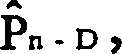
在接收调制解调器200中,接收信号以常规方式由均衡器/解调器201进行处理,产生一个被污染的信号点


图2是一个N态网格编码器106的示范性实施方案,其中N=8。S/P变换器104到网格编码器106的输入包括4个在信令间隔n中接收的数据比特I1n到I4n。网格编码器106示范性地是一个系统编码器,这意味着它的每个输入数据比特经过编码器传递,不加改变地成为它的一个输出比特。网格编码器106具有一个附加的输出比特Y0n——也就是所谓的冗余比特。特别是,编码器106是一个有限状态机,其中编码器状态W1nW2nW3n由当前存储在它的三个T秒延迟元件中的比特值来定义。从图中可以看出,比特Y0n的值是当前编码器状态的函数。FIG. 2 is an exemplary implementation of an N-state trellis encoder 106, where N=8. The input of the S/P converter 104 to the trellis encoder 106 comprises the 4 data bits I1 n to I4 n received in the signaling interval n. Trellis encoder 106 is exemplary a systematic encoder, meaning that each of its input data bits passes through the encoder, unchanged, becoming one of its output bits. Trellis encoder 106 has an additional output bit Y0 n —the so-called redundancy bit. In particular, encoder 106 is a finite state machine, where the encoder state W1 n W2 n W3 n is defined by the bit values currently stored in its three T-second delay elements. As can be seen from the figure, the value of bit Y0 n is a function of the current encoder state.
更为特别的是,三个T秒延迟元件通过所示的两个异或门相互连接。由于在任何时间点上,三个延迟元件中的每一个都可以包含一个二进制比特“0”或“1”,因此网格编码器具有N=23=8种所谓的状态,实际上它被叫做8态编码器。当得到用于每个新的信令间隔的新的一组I1n和I2n的值的时候,存储在延迟元件中的比特值被更新,由此使编码器前进或转移到新的状态W1n+1W2n+2W3n+3。该过程不断被重复,用于使信令间隔保持连续,编码器则沿着一个状态序列转移。More specifically, the three T-second delay elements are connected to each other through the two XOR gates shown. Since each of the three delay elements can contain a binary bit "0" or "1" at any point in time, the trellis encoder has N=2 3 =8 so-called states, which are actually It is called an 8-state encoder. When a new set of values for I1 n and I2 n is obtained for each new signaling interval, the bit values stored in the delay elements are updated, thereby causing the encoder to advance or transition to a new state W1 n+1 W2 n+2 W3 n+3 . This process is repeated continuously to keep the signaling intervals continuous and the encoder transitions along a sequence of states.
星座图映射部件108使用比特Y0n到Y4n的值,来判定预定的32个信号点的星座图中,哪一个信号点应被当作信号点Pn来传输。这个星座图在图3中给出。该星座图包括信号点A到H的8个发射机子集,每一个依次包括4个信号点,如图所示。比特Y0n到Y2n确定从8个发射机子集中的哪一个来得到信号点Pn。比特Y3n和Y4n的值在被确认的发射机子集中的4个信号点中选择特定的一个作为Pn。编码器106的结构使得实际上并非所有的状态序列都会出现。因此,实际上并非所有的三比特组合序列Y2nY1nY0n都会出现。总的结论是图3的星座图的信号点被允许只能从一定的发射机子集序列中获得。这种约束使得在一个网格编码系统中接收到的信号以这样一种方式被解码,该方式提供了对噪声和其它信道损伤的增强了的抗御能力。The constellation mapping part 108 uses the values of the bits Y0 n to Y4 n to determine which signal point should be transmitted as the signal point P n in the predetermined constellation of 32 signal points. This constellation diagram is given in Figure 3. The constellation diagram includes 8 transmitter subsets of signal points A to H, each of which in turn includes 4 signal points, as shown. Bits Y0 n to Y2 n determine from which of the 8 subsets of transmitters the signal point P n is derived. The value of bits Y3 n and Y4 n selects a specific one as P n among the 4 signal points in the identified subset of transmitters. The structure of encoder 106 is such that not all sequences of states occur in practice. Therefore, not all three-bit combination sequences Y2 n Y1 n Y0 n will appear in practice. The general conclusion is that the signal points of the constellation diagram of Fig. 3 are allowed to be obtained only from a certain sequence of transmitter subsets. This constraint enables signals received in a trellis coding system to be decoded in a manner that provides increased resilience to noise and other channel impairments.
图4的8态网格图从另一个方面说明了网格编码器106的运作。网格编码器106的八种状态以0到7表示。图4中由点所构成的两条垂线分别代表可能的当前和下一个编码器状态。网格图为每个当前编码器状态限定编码器被允许转移的下一个状态。连接不同状态对的线或分支表示被允许的状态转移。例如,编码器可以从当前状态0转移到下一个状态0,1,2,3中的任何一个,但却不能转移到其他任何状态。The 8-state trellis diagram of FIG. 4 illustrates the operation of the trellis encoder 106 from another aspect. The eight states of trellis encoder 106 are denoted 0-7. The two vertical lines formed by dots in Fig. 4 represent possible current and next encoder states, respectively. The trellis diagram defines for each current encoder state the next state the encoder is allowed to transition to. Lines or branches connecting different pairs of states represent permitted state transitions. For example, an encoder can transition from the
图4中每条分支都标有一个标签,用于表示正在产生的的信号点是来自发射机子集A到H中的哪一个。至于状态0,标记被显示为邻近于对应的分支。但为了绘图简单,其他状态所发出的分支,其标签只在网格左边的栏中显示。因此,举例来说,连接状态1到状态4、5、6、7的分支被分别标记为E、G、F、H。Each branch in Fig. 4 is marked with a label, which is used to indicate which of the transmitter subsets A to H the signal point is being generated from. As for
假定编码器当前状态是0,并且在接收了一对新的输入比特Y1n和Y2n之后,现在编码器处于状态1。这意味着将要输出的下一个信号点来自发射机子集C,因为将左栏中状态0连到右栏中状态1的线被标记为C。由于现在编码器处于状态1(编码器当前新的状态),编码器可以转移到状态4、5、6、7中的任何一个,因此下一个信号点被限制为来自发射机子集E、F、G或H中的一个,这取决于编码器已经转移到这些状态中的哪一个。Suppose the current state of the encoder is 0, and after receiving a new pair of input bits Y1 n and Y2 n , the encoder is now in
与一个特定的网格编码相关的网格图的连锁序列中包括一个网格结构。例如图5所显示的对应于图4中网格图的网格结构。特别是,图5表示网格编码器可能的连续状态转移。一个从任意互联分支序列中选出的信号点序列是一条通过该网格结构的所谓的路径。A trellis structure is included in the concatenation sequence of trellis diagrams associated with a particular trellis code. For example, the grid structure shown in FIG. 5 corresponds to the grid diagram in FIG. 4 . In particular, Fig. 5 shows the possible successive state transitions of a trellis encoder. A sequence of signal points selected from any sequence of interconnected branches is a so-called path through the lattice structure.
传统的网格编码信号的Viterbi解码使用与在发射机中所使用的相同的子集划分和网格图。在实施本发明原理的设备中所进行的解码,也可以使用相同于与发射机中所使用的子集划分和网格图,就如我在98年2月12日提交的,申请号为09/023063,题为“用于依赖于信号的噪声的面向路径的解码器”的待审美国专利申请中所描述的那样。这种装置将提供对变换增益的一定测量。然而,图1中的系统示范性地遵循我在上面引证的‘268待审申请中给出的更为成熟的方法。在这种方法中,接收到的网格编码信号点使用一个精选的接收机网格图来进行解码,尽管在发射机中它们已被分成了比它们实际更好的编码子集——称为接收机子集。使用一个精选的接收机网格,而不是先前的技术方法,就能够为信号点实际发送的内容提供更好的估算,并且与下文中将要详细描述的面向路径的方法相联合,就能够实现甚至更高程度的转换增益。获得转换增益的方式可以参见图6、7、8。Conventional Viterbi decoding of trellis coded signals uses the same subset division and trellis diagram as used in the transmitter. The decoding performed in the device implementing the principles of the present invention can also use the same subset division and trellis as used in the transmitter, as I filed on February 12, 98, application number 09 /023063, as described in pending US patent application entitled "Path-Oriented Decoder for Signal-Dependent Noise". Such a device will provide some measure of conversion gain. However, the system in Figure 1 exemplarily follows the more sophisticated approach I have given in the '268 co-pending application cited above. In this approach, the received trellis coded signal points are decoded using a carefully selected receiver trellis map, although at the transmitter they have been divided into better coded subsets than they actually are - called for the receiver subset. Using a well-chosen grid of receivers, rather than prior art approaches, can provide better estimates of what a signal point is actually transmitting, and in conjunction with the path-oriented approach described in detail below, enables even higher degrees of conversion gain. See Figures 6, 7, and 8 for ways to obtain conversion gain.
如图6所示,图3的8个发射机子集A到H中的每一个进一步被示范性地划分为两个接收机子集,A1和A2,B1和B2及其它。划分是以这样一种方式进行,在任意接收机子集中,信号点间的最小距离要大于任意发射机子集中信号点间的最小距离。在每个接收机子集中并不需要具有相同数目的信号点。因此,举例来说,接收机子集A1和A2分别具有一个和三个信号点。另一方面,接收机子集B1和B2中的每一个都具有两个信号点。如果希望,发射机被划分成的接收机子集的数目可以与信道条件相适配。As shown in FIG. 6, each of the eight transmitter subsets A to H of FIG. 3 is further exemplarily divided into two receiver subsets, A1 and A2 , B1 and B2 and others. The partitioning is done in such a way that the minimum distance between signal points in any subset of receivers is greater than the minimum distance between signal points in any subset of transmitters. It is not necessary to have the same number of signal points in each receiver subset. So, for example, receiver subsets Al and A2 have one and three signal points, respectively. On the other hand, each of receiver subsets B1 and B2 has two signal points. The number of receiver subsets into which the transmitter is divided can be adapted to the channel conditions, if desired.
图7表示了前面提到的精选的接收机网格图。精选的接收机网格图具有与发射机网格图的状态转移相对应的状态转移,并且与图4的发射机网格图是相同的,除了它对每一个状态转移都具有两个分支这一点之外,其中每个分支与较好的接收机子集中的一个相关联,该较好的接收机子集是与状态转移相关联的发射机子集的一部分。因此,举例来说,图4中与连接当前状态0到下一状态1的子集C相关联的状态转移,在图7中被两条分别与接收机子集C1和C2相关联的平行分支所替代。Figure 7 shows a selection of receiver trellis diagrams mentioned above. The selected receiver trellis diagram has state transitions corresponding to the state transitions of the transmitter trellis diagram, and is identical to the transmitter trellis diagram of Figure 4, except that it has two branches for each state transition In addition, each branch is associated with one of the better subset of receivers that is part of the subset of transmitters associated with the state transition. Thus, for example, the state transition in Figure 4 associated with subset C connecting the
如前面指出的,接收机200中的联合DFE/解码器202在对一个接收到的信号点Pn进行解码前,先对其进行判定反馈均衡。图8详细显示了这一点。As noted earlier, the joint DFE/decoder 202 in the receiver 200 performs decision feedback equalization on a received signal point Pn before decoding it. Figure 8 shows this in detail.
特别是,图8显示了一个M路联合DFE/解码器,其中形成了M=16的

图8中对解码器830的描述显示了16个经过树状结构扩展的所谓的存在路径#1到#16其中的4个,所示的这4个路径是路径#1、#2、#3和#16。为了绘图简单,其他12个存在路径没有被表示出。沿着每条路径的信号点构成了一个假定信号点判决序列。每条存在路径都保留一个度量,并且如下所述,当前均衡信号Xn (第1路)到Xn (第16路)被用于判定具有被更新的路径度量的新的存在路径。在其上产生一个最终判决
DFE820中的每一个都与存在路径#1到#16中特定的一个相关联。尤其每个DFE产生前面提到的各个估算所得的ISI成分,或ISI估算,作为在沿着相关的存在路径上的假定信号点判定的一个函数。这时,沿着每条存在路径的假定信号点判定整体地被应用到相关的DFE中,为应用到加法器810的ISI估算的生成做准备。特别是,众所周知,DFE是通过形成判定的组合(例如线性组合)来形成其ISI估算的,这些判定是使用一个其值通常是自适应地更新的系数整体来输入到DFE中的。因此,均衡信号Xn (第1路)到Xn (第16路)中的每一个都与一个特定的存在路径相关联,这是因为用于形成均衡信号的ISI估算是被作为相关的存在路径的函数而产生的。Each of DFE 820 is associated with a specific one of
上面提到的使用当前均衡信号Xn (第1路)到Xn (第16路)来判定具有更新的路径度量的新的存在路径的过程,是通过解码器830中的更新单元831来完成的。为了得到根据图7的接收机网格图,从M=16条存在路径中发出的,当前到下一个状态的128条分支,对所谓的分支度量加以计算(简单起见,仅有几条这样的分支在图8中被表示)。每条分支的支的度量被均衡信号Xn (第1路)到Xn (第16路)中的一个和与该分支相关的接收机子集中最近的信号点之间的欧几里德距离的平方所给出。用于计算任意给定分支度量之一的均衡信号Xn (第1路)到Xn (第 16路)中特定的一个,是与分支发出的存在路径相关联的均衡信号。在该点有128条候选路径,其中有8条是从16条存在路径中的每一个引出的。每条候选路径都具有一个关联的度量,该度量是由对应于存在路径的当前路径度量和对应分支的分支度量之和所给出的。The above-mentioned process of using the current equalized signals Xn (No. 1) to Xn (No. 16) to determine a new existing path with an updated path metric is completed by the update unit 831 in the decoder 830 of. In order to obtain the receiver trellis diagram according to Fig. 7, the 128 branches from the current to the next state sent out from M=16 existing paths, the so-called branch metrics are calculated (for simplicity, there are only a few such branches are represented in Figure 8). The branch of each branch measures the Euclidean distance between one of the equalized signals X n (way 1) to X n (way 16) and the nearest signal point in the receiver subset associated with that branch given by the square. A particular one of the equalized signals Xn (way 1) to Xn (way 16) used to calculate one of the metrics for any given branch is the equalized signal associated with the existing path from which the branch originated. At this point there are 128 candidate paths, 8 of which emanate from each of the 16 existing paths. Each candidate path has an associated metric given by the sum of the current path metric corresponding to the existing path and the branch metric of the corresponding branch.
在用于Viterbi解码器的传统的面向状态的方法中,只有一条进入一个状态的路径可以被称为是一条存在路径。然而,联合DFE/解码器202使用了在我前面提到的待审‘268和‘063专利申请中的“面向路径”的方法。也就是说,被保留作为存在路径的路径是那些具有最小更新路径度量的M条候选路径,即使这意味着引入相同的下一编码器状态的两条候选路径都被保留。如上面所指出的,由每个DFE所产生的ISI估计是经过网格的各条存在路径的一个函数。因此,每一个ISI已被补偿的信号Xn (第1路)到Xn (第16路)也是某一存在路径的函数。分支度量又是每一个ISI已被补偿的信号的函数。那么最终,从任意给出路径延伸出的分支,其分支度量本身是路径本身的一个函数。因此,在一个特定时间点具有最小度量的路径,一旦被延伸之后,就可能不具有最小路径度量,因为每条分支的分支度量——即使是从相同状态延伸出的——都是取决于路径的并因此不同。In the traditional state-oriented approach for Viterbi decoders, only one path into a state can be said to be an existential path. However, the joint DFE/decoder 202 uses the "path-oriented" approach in the co-pending '268 and '063 patent applications I mentioned earlier. That is, the paths that are kept as existing paths are those M candidate paths with the smallest updated path metric, even if this means that both candidate paths that introduce the same next encoder state are kept. As noted above, the ISI estimate produced by each DFE is a function of the existing paths through the grid. Therefore, each ISI-compensated signal Xn (1st path) to Xn (16th path) is also a function of an existing path. The branch metric is in turn a function of each ISI-compensated signal. Ultimately, then, the branch metric of a branch from any given path is itself a function of the path itself. Thus, a path with the minimum metric at a particular point in time, once extended, may not have the minimum path metric, since the branch metric of each branch—even if extended from the same state—depends on the path and therefore different.
如前面提到的,解码过程得到一个最终判定 作为在D个信令间隔之前传输的信号点的值。通过提供将该ISI成分作为存在路径的函数,较早收到的信号点的分散信号能量被返回给该信号点。因此,变换增益得以实现,并且得到了更为准确的解码。As mentioned earlier, the decoding process results in a final decision as the value of the signal point transmitted before D signaling intervals. Dispersed signal energy from earlier received signal points is returned to the signal point by providing this ISI component as a function of the existing path. Therefore, transformation gain is realized and more accurate decoding is obtained.
上述的解码过程对在所谓的连续传输环境中的应用来说是非常合适的,该环境中有大量信号点被传输。在这样的应用中,除了最后少数几个接收信号点,在较早收到的信号点之后都有信号点,通过这些信号点较早收到的信号点的信号能量可以被集中,以实现解码过程所提供的转换增益。况且,许多虚假信号点可以随着数据信号点的传输而被发送,以便于能够集中末端有用数据信号点的ISI成分——并因此提供与之相关的转换增益——通过相对地不显著的开销,给出大量的被传输的有用数据信号点。The decoding process described above is very suitable for applications in so-called continuous transmission environments, where a large number of signal points are transmitted. In such applications, except for the last few received signal points, there are signal points after the earlier received signal points, through which the signal energy of the earlier received signal points can be concentrated for decoding The conversion gain provided by the process. Moreover, many spurious signal points can be sent along with the transmission of data signal points in order to be able to concentrate the ISI component of the end useful data signal point - and thus provide the conversion gain associated therewith - with relatively insignificant overhead , giving a large number of useful data signal points to be transmitted.
上述解码过程也可以被用在分组传输环境中,其中信号点在连续的分离的分组或通信中传输,分组或通信中的每一个都包括一个数量上相对较少的信号点(通常大约是几百个)。然而,在一个分组传输环境中,这种解码过程的优点并没有得到充分实现。特别是只有较少数目的后续信令间隔,通过这些信令间隔被传输信号点的分散ISI能量可以被集中,并返回到各个信令间隔中,其中,在一个分组中最后少数几个信号点被传输。此外,跟随数据信号点的虚假信号点的传输将使带宽效率(平均每个信令间隔中的有用数据比特数)降低到一个由分组中包含的相对数目较少的信号点所给出的,非常不利的程度。因此,转换增益至少没有为这些“末端”信号点实现,并且因此末端信号点的解码可靠性要比那些转换增益得到确保的信号点的差。涉及其他信号点的末端各信号点的不可靠性将会对总体性能造成决定性的影响,这是很不利的,因为在一些应用中,即使分组中只有一个信号点出错,那么整个分组都会被标记为出错并且必须重传。The decoding process described above can also be used in a packet transmission environment, where signal points are transmitted in successive separate packets or communications, each of which includes a relatively small number of signal points (typically on the order of several hundred). However, in a packet transmission environment, the advantages of this decoding process are not fully realized. In particular there are only a small number of subsequent signaling intervals through which the scattered ISI energy of the transmitted signal points can be concentrated and returned to the individual signaling intervals where the last few signal points in a packet is transmitted. Furthermore, the transmission of false signal points following data signal points will reduce the bandwidth efficiency (average number of useful data bits per signaling interval) to a value given by the relatively small number of signal points contained in the packet, very unfavorable degree. Consequently, conversion gain is not realized at least for these "end" signal points, and the decoding reliability of the end signal points is therefore worse than those for which the conversion gain is ensured. The unreliability of the signal points at the end of other signal points will have a decisive impact on the overall performance, which is very disadvantageous, because in some applications, even if only one signal point in the group is wrong, the entire group will be marked An error occurred and must be retransmitted.
克服上面的问题要根据本发明的原理,通过使出现在信号点流量中预定位置,较少受益于抗误码能力增强的信号点以这样一种方式传输,使得在这种方式中其对抗误码的稳健性至少跟从抗误码能力增强的特定形式受益更多的信号点一样强。也就是说,对较少受益于特定形式的抗误码能力增强的信号点所进行解码的出错概率,实质上与对其他信号点所进行解码的出错概率是一样的。因此,本发明排除了末端信号点会对例如分组传输信令方案的总误码率起决定性影响的上述问题。Overcoming the above problems is based on the principles of the present invention, by having signal points less likely to benefit from enhanced error resistance by appearing at predetermined positions in the signal point traffic to be transmitted in such a way that they are resistant to error The robustness of the code is at least as strong as the signal points that benefit more from a particular form of error robustness enhancement. That is, the probability of error in decoding signal points that benefit less from a particular form of error robustness enhancement is substantially the same as the probability of error in decoding other signal points. Thus, the invention excludes the above-mentioned problem that the end signal point can have a decisive influence on the overall bit error rate of eg a packet transmission signaling scheme.
在本发明公开的示范性的分组传输实施例中,分组的末端信号点是使用一个具有比用于那些在它们之前的信号点的星座图中信号点少的星座图来进行传输的,使得末端信号点可以进一步从信号空间中彼此分开。这样就可以承受更多的噪声,使得末端信号点的总体误码性能不比其它信号点的差。这样,实质上可以使分组传输总的分组误码率与连续传输时相同,因为(a)分组中较早出现的信号点受益于转换增益,并且(b)其他形式的增强的抗误码能力被提供给那些没有受益于转换增益的末端信号点。此外,本发明显著地改进了如上所述使用虚假信号点所引起的带宽效率的降低。In the exemplary packet transmission embodiment disclosed in the present invention, the terminal signal points of the packet are transmitted using a constellation having fewer signal points than the constellation used for those signal points preceding them, such that the terminal Signal points can be further separated from each other in signal space. In this way, more noise can be tolerated, so that the overall bit error performance of the end signal point is not worse than that of other signal points. In this way, the overall packet error rate for packet transmission can be substantially the same as for continuous transmission, because (a) signal points occurring earlier in the packet benefit from conversion gain, and (b) other forms of enhanced error immunity are provided for those end signal points that do not benefit from conversion gain. Furthermore, the present invention significantly improves the reduction in bandwidth efficiency caused by the use of false signal points as described above.
因此在示范性的实施例中,发射机101产生一个在Q个信号间隔中具有Q=(J+K+L)个信号点的分组,如图9的发射机网格所说明的那样。特别是,网格编码器106从“开始状态”到“终止状态”的连续状态转移代表前J+K个信令间隔,如上面所提到的,编码器106的状态是由存储在其三个T秒延迟元件中的比特值来定义的——这些比特值被称作状态变量W1n,W2n和W3n。在图9中,编码器开始状态示范性地为零状态(也就是状态变量的初始值为0)。对前J个信令间隔中的每一个来说,如图2所示,4个数据比特被提供到网格编码器106中,并以上述方式进行处理。Thus in the exemplary embodiment, transmitter 101 generates a packet with Q=(J+K+L) signal points in Q signal intervals, as illustrated by the transmitter grid of FIG. 9 . In particular, the successive state transitions of the trellis encoder 106 from the "start state" to the "end state" represent the first J+K signaling intervals, as mentioned above, the state of the encoder 106 is determined by the state stored in its three defined by bit values in delay elements of T seconds - these bit values are called state variables W1 n , W2 n and W3 n . In FIG. 9 , the start state of the encoder is exemplarily the zero state (that is, the initial value of the state variable is 0). For each of the first J signaling intervals, as shown in FIG. 2, 4 data bits are provided to trellis encoder 106 and processed in the manner described above.
在使用了本发明的没有网格编码的系统中,按照本发明的原理,使用比末端信号点之前的信号点的星座图小的信号点星座图,来完成上述末端信号的传输,这是一件直截了当的事。然而本实施例中使用了编码。因此,为了使编码的信号点能被准确地解码,而不需要足够多的虚假信号点传输来覆盖编码深度,网格编码应被引导到一种已知状态,或者以已知方式终结。此后本发明将被应用到那些用于终结的信号点之后的信令点上。In the system without trellis coding using the present invention, according to the principle of the present invention, the signal point constellation diagram smaller than the constellation diagram of the signal point before the terminal signal point is used to complete the transmission of the above-mentioned terminal signal, which is a A straightforward matter. However, encoding is used in this embodiment. Therefore, in order for coded signal points to be accurately decoded without requiring enough spurious signal point transmissions to cover the coded depth, trellis codes should be steered to a known state, or terminated in a known manner. Hereafter the present invention will be applied to signaling points following those signaling points for termination.
更为特殊的,编码终结通常是通过提供一定的附加或混合到最后几个数据比特中的输入比特来得到的,这几个数据比特是通过使用这样一种方式,使编码器在接收机已知的预定状态中被终结。(对终结编码器状态的认识使得接收机能够立即判定极佳存在路径——通过该路径产生对信号点的判定——因为在该状态中没有终结的存在路径可以不予考虑。因此,通过沿着极佳存在路径进行反向追溯,就能立即作出对信号点的判定。)可以从图9中看出,在第(J+K)个信令间隔的末端,编码器已经从它的开始状态转移到其终止状态,示范性地为零状态。(开始和终止状态并不必须为零状态,实际上并不必是同一种状态。然而开始和终止状态对解码器来说必须是已知的。)编码器进入其终止状态——也就是说,终止编码——是在经过K个信令间隔之后才实现的,举例来说,K等于2。它的完成是通过(a)对第(J+1)个信令间隔来说,仅向网格编码器106提供3个数据比特,I2n到I4n,I1n被设置成与W2n的值相等,以及(b)对后续的第(J+K)个信令间隔——也就是第(J+2)个信令间隔来说,——仅向网格编码器106提供2个数据比特I3n和I4n,I1n和I2n的值被分别设置成等于W2n和W1n的值。More specifically, code termination is usually achieved by providing certain input bits that are appended or mixed into the last few data bits in such a way that the coder terminated in a known predetermined state. (Knowledge of the terminating encoder state enables the receiver to immediately determine the best existing path - the path through which the decision to the signal point is made - because an existing path that has no termination in this state can be disregarded. Therefore, by following can immediately make a decision on the signal point.) It can be seen from Fig. 9 that at the end of the (J+K)th signaling interval, the encoder has started from its beginning A state transitions to its terminal state, illustratively the zero state. (The start and end states do not have to be the zero state, and indeed do not have to be the same state. However, the start and end states must be known to the decoder.) The encoder enters its end state—that is, Termination coding—is implemented after K signaling intervals, for example, K is equal to 2. It is accomplished by (a) providing only 3 data bits, I2 n to I4 n , for the (J+1)th signaling interval, to trellis encoder 106, with I1 n being set to be equal to W2 n values are equal, and (b) for the subsequent (J+K)th signaling interval—that is, for the (J+2)th signaling interval—only 2 data are provided to the trellis encoder 106 The values of bits I3 n and I4 n , I1 n and I2 n are set equal to the values of W2 n and W1 n , respectively.
对前(J+K)个信令间隔中的每一个来说,5个编码器的输出比特,Y0n-Y4n,被提供到星座图映射部件108,如上所述,该部件使用它们来判定图3中示范性星座图的信号点,哪一个应被作为信号点Pn来传输。在前J个信令间隔中产生的信号点,在这里被称作主数据信号点在其后的K=2的后继信令间隔中,作为编码终结过程的一部分而产生的各信号点被称为编码终结信号点。For each of the first (J+K) signaling intervals, the output bits of the 5 encoders, Y0n-Y4n, are provided to the constellation mapping block 108, which uses them to determine the constellation mapping block 108 as described above. Which of the signal points of the exemplary constellation diagram in 3 should be transmitted as the signal point Pn . The signal points generated in the first J signaling intervals are referred to here as main data signal points. In the following K=2 subsequent signaling intervals, the signal points generated as part of the coding termination process are called Signal point for encoding termination.
后续的L个信令间隔中的数据比特是根据本发明的原理来进行处理的。特别是,在本示范性的实施例中,在那些较少受益于转换增益的信令间隔中传输的信号点,以这样一种方法进行传输,使得它们对抗误码的稳健性至少与从其中受益更多的(J+K)个先前的信号点的一样强。更具体地说,在这里被称作路径终结信号点的这些信号点,示范性地是从一个更小的星座中选出的,也就是该星座图比用于先前的信令间隔的星座图具有更少的信号点。举例来说,这个更小的星座图是一个图11的2QAM星座图。在优选实施例中,这个预定的更小星座图遵循下面将要讨论的一定的设计原则。图11中的星座图是由两个信号点r1和r2组成的,构成了一个单独的发射机子集R。The data bits in the subsequent L signaling intervals are processed according to the principle of the present invention. In particular, in this exemplary embodiment, signal points transmitted in those signaling intervals that benefit less from conversion gain are transmitted in such a way that they are at least as robust against bit errors as from which Benefit more (J+K) previous signal points as strong. More specifically, these signal points, referred to herein as path termination signal points, are exemplarily selected from a smaller constellation, i.e. the constellation is smaller than the constellation used for the previous signaling interval has fewer signal points. For example, this smaller constellation is a 2QAM constellation of FIG. 11 . In a preferred embodiment, this predetermined smaller constellation follows certain design principles discussed below. The constellation diagram in Fig. 11 is composed of two signal points r1 and r2 forming a single subset R of transmitters.
对第(J+K+1)个到第Q个信令间隔中的每一个来说,星座映射程序108使用了一个数据比特来选择两个信号点中的一个。编码器继续保持终结状态,并且如图12所示,对应的发射机网格图包括一个单独节点,用于每一个具有一条连接单独当前状态到下一状态的分支的信令间隔。该分支被标记为R,表示每个将要传输的信号点都是子集R中的一员。因此如图9所示,从第(J+K+1)个信令间隔延伸到第Q个信令间隔的网格是图12的单独分支的网格图的一个连锁。因此路径终结信号点中的每一个都是由同一个子集R中选出的。For each of the (J+K+1)th through Qth signaling intervals, the constellation mapping procedure 108 uses one data bit to select one of two signal points. The encoder continues to hold the terminal state, and as shown in Figure 12, the corresponding transmitter trellis diagram includes a single node for each signaling interval with a branch connecting a single current state to the next state. This branch is marked R, indicating that each signal point to be transmitted is a member of the subset R. Thus, as shown in FIG. 9 , the trellis extending from the (J+K+1)th signaling interval to the Qth signaling interval is a concatenation of the trellis diagram of the individual branches of FIG. 12 . Therefore, each of the path termination signal points is selected from the same subset R.
概括起来,一个具有Q个信号点的分组被传输。分组中包括主数据信号点,编码终结信号点以及路径终结信号点,所有这些都是携带数据的。(对下文将要更为详细描述的未编码应用来说,不需要编码终结信号点,因此路径终结信号点紧随主数据信号点。)一个受到噪声和ISI污染的信号点被接收机200接收,并且特别是,由恢复被传输的各信号点的M路联合DFE/解码器202接收。To summarize, a packet with Q signal points is transmitted. Packets include main data signal points, end-of-code signal points, and end-of-path signal points, all of which carry data. (For unencoded applications, described in more detail below, the end signal point does not need to be encoded, so the path end signal point immediately follows the main data signal point.) A signal point contaminated by noise and ISI is received by the receiver 200, And in particular, received by the M-way joint DFE/decoder 202 recovering the transmitted signal points.
图10显示了用于对传输的信号点分组进行解码的接收机网格。可以看出,对路径终结信号点来说,接收机网格与发射机网格相对应,因为只有一种状态和一条从当前状态到下一状态的分支。对主数据信号点和编码终结信号点来说,接收机网格示范性的是由图7中精选的接收机网格图的连锁序列所构成的。也就是说,对这些信号点来说,尽管发射机网格基于星座图的8子集划分,但被联合DFE/解码器所使用的接收机网格则是基于16子集划分。Figure 10 shows the receiver grid used to decode the transmitted signal point packets. It can be seen that for path termination signal points, the receiver grid corresponds to the transmitter grid, since there is only one state and one branch from the current state to the next state. For the main data signal point and the code termination signal point, the receiver trellis is exemplarily formed by a concatenated sequence of the selected receiver trellis diagrams in FIG. 7 . That is, for these signal points, while the transmitter grid is based on an 8-subset partition of the constellation, the receiver grid used by the joint DFE/decoder is based on a 16-subset partition.
如前面所描述的,响应于接收的主数据和编码终结信号点,经过精选的接收机网格的连续几组M条存在信号点被识别,使得至少一条对应于各个发射机信号点的一个具体序列的路径能被确认为存在路径之一。在第(J+K)个信令间隔中,终结于编码终结状态(例如状态0)的M条存在路径,以相同于上述方式的方式被扩展——其中ISI成分作为存在路径的函数——当受到污染的信号点被接收时。具有路经终结信号点这个事实保证了所有先前的各信令点都能充分地享受由面向路径的联合解码器/DFE所提供转换增益的好处。As previously described, in response to the received main data and coded termination signal points, consecutive sets of M presence signal points through a carefully selected receiver grid are identified such that at least one corresponds to one of each transmitter signal point A specific sequence of paths can be identified as one of the existing paths. In the (J+K)th signaling interval, the M existence paths terminating in a coded termination state (e.g. state 0) are expanded in the same manner as above—with the ISI component as a function of the existence paths— When a tainted signal point is received. The fact of having a path-terminating signal point ensures that all previous signaling points can fully benefit from the conversion gain provided by the path-oriented joint decoder/DFE.
被传输的各信号点以常规方式,经过接收机网格,沿着极佳存在路径反向追溯得以恢复。特别是,对在第D个信令间隔之后的一个信令间隔(除了第Q个信令间隔之外)来说,其中D是解码深度,联合DFE/接收机提供一个对在D个信令间隔之前接收的信号点的最终判定。在第Q个信令间隔中,当最后一个信号点被接收之后,通过沿着终止于该第Q个信令间隔的M条存在路径中的极佳路径反向追溯到判定停止处对未能产生判定的信号点作出最终判定。在一些分组传输应用中,任何判定的作出都被延迟到分组中最后一个信号点被接收。那时,所有沿极佳路径追溯到分组开始而得到的各信号点都同时被宣布为传输的信号点。The transmitted signal points are recovered in a conventional manner by tracing backwards along the path of existence through the receiver grid. In particular, for a signaling interval (except for the Qth signaling interval) after the D signaling interval, where D is the decoding depth, the joint DFE/receiver provides a pair of Final decision on signal points received before the interval. In the Qth signaling interval, after the last signal point is received, trace back to where the decision stopped by following the optimal path among the M existing paths that terminated in the Qth signaling interval. The signal point that produces the decision makes the final decision. In some packet transmission applications, any decision making is delayed until the last signal point in the packet is received. At that time, all signal points obtained along the optimal path back to the beginning of the packet are simultaneously declared as signal points for transmission.
如前面指出的,在优选实施例中,用于路径终结信号点传输的较小星座图遵循一定的设计规则。首先,这个较小星座的平均功率应该不大于用于主数据和数据终结信号点传输的较大星座图的平均功率,因为如果不这样的话,总的传输的平均功率将会增加。然而,单独违反这条规则并不会损害本发明的优越性。As noted earlier, in the preferred embodiment, the smaller constellations used for path termination signal point transmission follow certain design rules. First, the average power of this smaller constellation should not be greater than the average power of the larger constellation used for main data and data termination signal point transmissions, because otherwise the average power of the overall transmission will increase. Violation of this rule alone, however, does not detract from the superiority of the present invention.
其次,较小星座图的信号点之间的最小距离应该不小于每个接收机子集(例如A1、A2、B1、B2及其他)的信号点间的最小距离,也就是较大星座图的接收机子集的子集内部最小距离。如果后一个要求得不到满足,那么对路径终结信号点解码的精确度将不如其它信号点那样可靠,由此使本发明的一个目标失败。Second, the minimum distance between the signal points of the smaller constellation should not be smaller than the minimum distance between the signal points of each receiver subset (such as A1, A2, B1, B2 and others), that is, the receiver of the larger constellation The minimum distance within a subset of machine subsets. If the latter requirement is not met, then the accuracy of decoding the end-of-path signal points will not be as reliable as other signal points, thereby defeating one of the objectives of the present invention.
任何满足上述要求的星座都可以被用作路径终结信号点的较小星座图。构成较小星座图的信号点数目是许多因素的一个函数,这些因素诸如信道条件和用于主数据和编码终结信号点的较大星座图的尺寸。随着后一个星座图尺寸的增长,用作较小星座图的星座图的尺寸也会随之增长。例如,如果较大星座图是一个编码的64QAM,则较小的星座图可能是一个4QAM星座图。此外,尽管本实施例中的较小星座图可以包括,举例来说,在一个如B2这样的特定接收机子集中的信号点,但这样做会引入一个直流成分,这通常是不理想的。尽管并非必需的,然而从一个可执行性的角度来说,选择从较大星座图中选出的信号点作为较小星座图中的信号点是很方便的。Any constellation that meets the above requirements can be used as a smaller constellation of path termination signal points. The number of signal points making up the smaller constellation is a function of factors such as channel conditions and the size of the larger constellation for the main data and code termination signal points. As the latter constellation grows in size, the constellation used as the smaller constellation also grows in size. For example, if the larger constellation is a coded 64QAM, the smaller constellation may be a 4QAM constellation. Furthermore, although the smaller constellations in this embodiment may include, for example, signal points in a particular receiver subset such as B2 , doing so introduces a DC component, which is generally undesirable. Although not required, it is convenient from an implementability point of view to select selected signal points from the larger constellation as signal points in the smaller constellation.
如上面所指出的,本发明不仅适用于实现编码调制(其中N态发射机被使用,N大于1)的装置中,还可用于非编码调制(其中N为1)的装置中。在后一种装置中,发射机网格图仅具有N=1的状态,并且只有一种状态转移。图13-16举例说明了这种方法。As indicated above, the present invention is applicable not only in devices implementing coded modulation (where N-state transmitters are used, N greater than 1), but also in devices without coded modulation (where N is 1). In the latter arrangement, the transmitter trellis has only N=1 states, and there is only one state transition. Figures 13-16 illustrate this approach.
在非编码调制系统中的本发明的实施方案中,发射机101在Q’个信令间隔上产生具有Q’个信号点的分组,这Q’个信号点包括J个主数据信号点和L个路径终结信号点,也就是说,Q’=(J+L)。(由于这是一个非编码系统,因此不需要具有编码终结信号点,因为这里没有必须被终结的编码。)特别是,在变换器104输出端的并行比特被提供到星座图映射部件108,它转而使用这些比特来选择一个信道信号点(在非编码调制系统中,没有网格编码器)。In an embodiment of the invention in a non-coded modulation system, the transmitter 101 generates a packet with Q' signal points over Q' signaling intervals, the Q' signal points including J main data signal points and L path termination signal points, that is, Q'=(J+L). (Since this is a non-coded system, there is no need to have a code termination signal point, since there is no code that has to be terminated.) In particular, the parallel bits at the output of the transformer 104 are provided to the constellation map block 108, which in turn Instead, use these bits to select a channel signal point (in an uncoded modulation system, there is no trellis encoder).
更具体地说,对J个主数据信号点当中的每一个来说,转换器输出比特中的4个被星座图映射部件108用来选择一个来自预定信号点星座图的信号点作为一个主数据信号点,示范性的是从图3中的16-QAM星座图中选出的。由于该系统是非编码的,因此在网格编码方面没有星座图子集。然而,星座图中的所有16个信号点可以被认为是构成了一个单独的子集T。More specifically, for each of the J main data signal points, 4 of the converter output bits are used by the constellation map component 108 to select a signal point from a predetermined signal point constellation as a main data The signal points are exemplarily selected from the 16-QAM constellation diagram in FIG. 3 . Since the system is non-coded, there is no subset of constellations in terms of trellis coding. However, all 16 signal points in the constellation diagram can be considered as forming a single subset T.
对L个路径终结信号点中的每一个来说,一个转换器输出比特被星座映射部件108所使用,来从第二预定信号点星座图中选出一个信号点作为路径终结信号点,示范性地来自图14的2-QAM星座图。在优选实施例中,该第二预定信号点星座图遵循上述设计规则。图14中的星座图是由两个信号点s1和s2构成的,组成了一个单独发射机子集S。For each of the L path termination signal points, one converter output bit is used by the constellation mapping component 108 to select a signal point from the second predetermined signal point constellation as the path termination signal point, exemplary The ground comes from the 2-QAM constellation diagram of FIG. 14 . In a preferred embodiment, the second predetermined signal point constellation follows the above design rules. The constellation diagram in Fig. 14 is formed by two signal points s 1 and s 2 forming a subset S of individual transmitters.
在图15的发射机网格中对发射机101的运作加以说明。由于有可能要传输前J个信令间隔中从16-QAM星座图中所选出的任意信号点,以及在后L个信号间隔中,从2-QAM星座图中选出的信号点中的任意一个,因此发射机只有一种状态,这样网格是由一个单独分支的序列构成的。连接单个当前状态到单个下一状态的一个分支在前J个信令间隔的被标记为T,在这个间隔中,产生主数据信号点,这说明要在这些信令间隔中传输的下一个信号点是子集T的一员。类似地,将单个当前状态连到单个的下一状态的分支在后L个信令间隔被标记为S,表示将要在这些信令间隔中传输的下一信号点是子集S的一员。The operation of transmitter 101 is illustrated in the transmitter grid of FIG. Since it is possible to transmit any signal point selected from the 16-QAM constellation diagram in the first J signaling intervals, and any signal point selected from the 2-QAM constellation diagram in the next L signal intervals Either one, so the transmitter has only one state, such that the grid is formed from a sequence of individual branches. A branch connecting a single current state to a single next state is denoted T for the first J signaling intervals, during which the main data signal point is generated, which describes the next signal to be transmitted in these signaling intervals A point is a member of the subset T. Similarly, the branch connecting a single current state to a single next state is marked S in the last L signaling intervals, indicating that the next signal point to be transmitted in these signaling intervals is a member of subset S.
在接收机中,单独的发射机子集T示范性地被划分为8个精选的接收机子集T1到T8,如图16所示。图15的精选的接收机网格反映了这种划分,因为用于前J个信令间隔的单独分支中的每一个都由8条分支所替代,每一个都对应于8个接收机子集中的一个。用于对最终L个路径终结信号进行解码的网格部分保持与发射机网格中对应的部分相同。也就是说,对于这些信令间隔,在当前和下一状态之间只有一条分支,并且该分支与整个2QAM星座图相关联。解码以相同于上述编码情况的方式进行。In the receiver, the individual transmitter subset T is exemplarily divided into 8 selected receiver subsets T 1 to T 8 , as shown in FIG. 16 . The selected receiver grid of Fig. 15 reflects this division, as each of the individual branches for the first J signaling intervals is replaced by 8 branches, each corresponding to one of. The part of the trellis used to decode the final L path termination signals remains the same as the corresponding part in the transmitter trellis. That is, for these signaling intervals, there is only one branch between the current and next state, and this branch is associated with the entire 2QAM constellation. Decoding is performed in the same manner as in the encoding case described above.
图17提供了上述的网格编码分组传输环境中的M路联合DFE/解码器的组合框图/功能描述图。接收到的信号点
在部件1501中被处理,产生与M条存在路径中每一条相关联的均衡信号。也就是说,一个均衡信号Xn (第K路)是使用一个DFE来形成的,该DFE的输出是沿着第K条存在路径所作出的假定的过去判定,其中K为1,2,3,……,M。Fig. 17 provides a combined block diagram/functional description diagram of the M-way joint DFE/decoder in the trellis-coded packet transmission environment described above. Signal points received Processed in
在部件1503处,均衡信号Xn (第k路)被用来找出:a)与每条分支相关联的接收机子集中最接近的信号点,b)从与在当前第n个信令间隔中基于接收机网格(例如示范性的图10和图15中的接收机网格)的第k条存在路径相关联的状态发出的每条分支的分支度量。然后,在部件1505,M条最佳存在路径及其路径度量被更新,并且新的一组M条最佳存在路径被确认。具有最佳路径度量(例如,具有最小路径度量的存在路径)的新组中M条最佳存在路径之一被确认为极佳存在路径。在部件1507,通过为当前信令间隔n而沿着极佳存在路径反向追溯,与(a)关于在D个信号点之前传输的信号点值的最终判定


包含在一个分组中的路径终结信号点的恰当数目L取决于特定的ISI信道。ISI越严重,则L应取的值就越大,因为给出的信号点能量将被扩展到更多的相邻信令间隔中。因此,为了判定L的值,发射机应该被提供或能够从接收机中获取诸如信道长度这样的信息。或者,发射机可以作出关于信息的最坏情况估计。The proper number L of path termination signal points contained in a packet depends on the particular ISI channel. The more severe the ISI, the larger the value of L should be, because the given signal point energy will be extended to more adjacent signaling intervals. Therefore, in order to determine the value of L, the transmitter should be provided or be able to obtain information such as the channel length from the receiver. Alternatively, the transmitter can make a worst-case estimate of the information.
图18和19中所示的误码率曲线说明了本发明的优越性。这些图中每一个都显示了用于一个特定信道的曲线,该曲线描述了实验上被确定的,作为信道信噪比的函数的分组误码率,如图所示,每条曲线用于对应的解码方法。每一条连续曲线从右到左代表一个性能上的改进程度,因为较高程度的信道噪声,也就是较低的信噪比,在仍然得到一个给定分组误码率时,是可以忍受的。(在这些图的X轴所示的信噪比指的是信号功率和附加高斯噪声功率之间的比率,并没有包含ISI成分。然而曲线自身对ISI已经有所考虑。)The bit error rate curves shown in Figures 18 and 19 illustrate the advantages of the present invention. Each of these figures shows a curve for a particular channel describing the experimentally determined packet error rate as a function of the channel's signal-to-noise ratio. As shown, each curve is for the corresponding the decoding method. Each continuous curve from right to left represents a degree of improvement in performance, as higher levels of channel noise, ie lower SNR, are tolerable while still obtaining a given packet error rate. (The signal-to-noise ratio shown on the x-axis of these graphs refers to the ratio between the signal power and the additive Gaussian noise power, and does not include the ISI component. However, the curve itself already takes ISI into account.)
图18比较了3种用于非编码16QAM的不同解码方法,每一种跟前一种相比都具有性能上的增进:(1)使用常规的DFE;(2)使用一个联合12路DFE/解码器,它基于一个精选的16QAM星座图的8子集划分,但没有路径终结;(3)使用(2)中的方法,但是使用根据本发明中L=3的路径终结。由任何特定方法所得到的性能在与其他的相比较时,可以从处理增益方面来表述,这意味着给定了分组误码率的情况下,它们的性能曲线之间的信噪比的不同。可以很容易地从图18中看出,例如分组误码率为10-4时,如果没有执行路径终结,那么使用M路联合DFE/解码器所得到的处理增益中大部分都会丢失。这是因为根据本发明原理的路径终结方法为分组中主数据信号点提供最终判定,以便得益于转换增益,并且该方法还提供给路径终结信号点本身,使之获得改进了的抗误码能力。Figure 18 compares 3 different decoding methods for non-encoded 16QAM, each with a performance increase over the previous one: (1) using a conventional DFE; (2) using a joint 12-way DFE/decoding device based on a selected 8-subset division of the 16QAM constellation, but without path termination; (3) use the method in (2), but use path termination with L=3 according to the present invention. The performance obtained by any particular method can be expressed in terms of processing gain when compared to others, meaning the difference in signal-to-noise ratio between their performance curves for a given packet error rate . It can be easily seen from Fig. 18 that most of the processing gain obtained by using an M-way joint DFE/decoder is lost if path termination is not performed, for example, at a packet error rate of 10 −4 . This is because the path termination method according to the principles of the present invention provides a final decision for the main data signal point in the packet to benefit from the conversion gain, and the method also provides the path termination signal point itself for improved error resistance ability.
图19表示编码调制系统的结果。特别是,该图显示了一个具有常规DFE的非编码16QAM的基准曲线图。通过基于星座图的精选的16子集划分的16路联合DFE/解码器,使用2维8态网格编码32QAM,就能获得显著的较好的性能,其中只使用了编码终结。使用相同的编码和联合DFE/解码器能得到更好的性能,但目前只根据本发明的原理使用了编码终结和路径终结二者,其中L=3。Figure 19 shows the results for the coded modulation system. In particular, the figure shows a benchmark plot for non-coded 16QAM with conventional DFE. Significantly better performance can be achieved with 2-D 8-state trellis coding 32QAM with carefully selected 16-subset 16-way joint DFE/decoder based on the constellation, where only code termination is used. Better performance can be obtained using the same encoding and joint DFE/decoder, but currently only both encoding termination and path termination are used according to the principles of the present invention, where L=3.
上文仅仅描述了本发明的原理。例如,在对本发明原理具体化的装置中,是使用编码或非编码调制,如果希望,包含另一个编码“层”,例如里德-索罗蒙编码,也是可能的。这种编码将被应用到希望在调制之前被传递的数据比特中。因此在图1中,举个例子,一个里德-索罗蒙编码器或其它编码器可以被插入到加扰器102和串/并变换器104之间,并且一个里德-索罗蒙码解码器可以被插入到并/串变换器204和解扰器206之间。传统的交织和解交织同样可以使用,就如包含里德-索罗蒙编码时经常有的情况那样。The foregoing merely describes the principles of the invention. For example, in an arrangement embodying the principles of the invention, whether coded or non-coded modulation is used, it is also possible to incorporate another "layer" of coding, such as Reed-Solomon coding, if desired. This encoding will be applied to the data bits that are expected to be delivered prior to modulation. So in FIG. 1, for example, a Reed-Solomon encoder or other encoder can be inserted between the scrambler 102 and the serial/parallel converter 104, and a Reed-Solomon code A decoder may be inserted between the parallel/serial converter 204 and the descrambler 206 . Conventional interleaving and deinterleaving can also be used, as is often the case when Reed-Solomon coding is involved.
用作示例的实施例中的信道112示范性地可以是一条贯穿很长的有效物理距离的有线或无线通信信道,然而,本发明同样地可应用于其它称作“信道”的传输路径,其中包括例如音频和/或视频的磁性或其他记录介质。在这种装置中,就如在电信应用中那样,系统中把信号点输入到信道的这部分就是“发射机”,系统中接收来自信道的信号点的这部分就是“接收机”。The channel 112 in the exemplary embodiment may illustratively be a wired or wireless communication channel over a long effective physical distance, however, the invention is equally applicable to other transmission paths called "channels" in which Includes magnetic or other recording media such as audio and/or video. In such an arrangement, as in telecommunications applications, the part of the system that inputs signal points into a channel is the "transmitter" and the part of the system that receives signal points from the channel is the "receiver".
这里的方框图是表示实施本发明原理的,用于示例的电路的概念视图。类似地,可以意识到任何流程图、信号流图、状态转移图、伪代码以及诸如此类,都代表着不同的处理过程,它们都可以直接在计算机可读介质中被描述,并且通过计算机或处理器来执行,无论计算机或处理器是否被明确地表示出来,都是如此。The block diagrams herein are conceptual views representing illustrative circuitry embodying the principles of the invention. Similarly, it will be appreciated that any flow diagrams, signal flow diagrams, state transition diagrams, pseudocode, and the like, representing various processes, can be directly described on a computer-readable medium and manipulated by a computer or processor This is true whether or not a computer or processor is explicitly identified.
这些图中所示的不同部件的功能,包括被标记为“处理器”的功能块,都可以通过使用专用的硬件以及能够执行与适当的软件相关联的软件的硬件来提供。当配置了处理器时,这些功能可以由一个单独的专用处理器、或单独的共享处理器以及多个单独的处理器来提供,其中一些可以是共享的。此外,术语“处理器”或“控制器”的明确使用不应该被解释为专指能执行软件的硬件,同时还可以不受限制地、隐含地包括数字信号处理器(DSP)硬件、用于存储软件的只读存储器(ROM)、随机访问存储器(RAM)以及非易失性存储器。其他硬件,无论是常规的还是定制的,也可以被包括在其中。The functions of the various components shown in these figures, including the functional blocks labeled "processors", may be provided by the use of dedicated hardware as well as hardware capable of executing software in association with appropriate software. When processors are configured, these functions may be provided by a single dedicated processor, or a single shared processor as well as multiple separate processors, some of which may be shared. Furthermore, explicit use of the terms "processor" or "controller" should not be construed to refer exclusively to hardware capable of executing software, while also implicitly including, without limitation, digital signal processor (DSP) hardware, Read-only memory (ROM), random-access memory (RAM), and non-volatile memory for storing software. Other hardware, whether conventional or custom, may also be included.
在这里叙述的所有实例和附有条件的书面语言主要是特意地用于教学目的,以帮助读者理解本发明的原理和发明人为促进技术所提供的观点,并且将被解释为不受特别叙述的实例和条件的限制。此外,这里的所有陈述叙述了本发明的原理、特征和实施例,以及有关这方面的具体实例,意味着既包含了结构上的,又包含了功能上的等价物。另外,这意味着这样的等价物包括当前已知的等价物,还包括在以后将被开发出来的等价物,也就是说,包括任何被开发出来执行相同功能的部件,无论其结构是怎样的。All examples and proviso written language recited herein are primarily intended for instructional purposes, to assist the reader in understanding the principles of the invention and the viewpoints offered by the inventors to advance the art, and are to be construed as not expressly recited Limitations of Examples and Conditions. Moreover, all statements herein reciting principles, features and embodiments of the invention, as well as specific examples pertaining thereto, are meant to encompass both structural and functional equivalents. Additionally, it is intended that such equivalents include currently known equivalents as well as equivalents to be developed in the future, that is, any components developed to perform the same function, regardless of structure.
类似地,在关于本发明的权利要求中,任何被表述为执行一种特定功能的装置的部件都包含执行该功能的任何方法,其中包括:例如,(a)完成这个功能的电路元件的组合,或(b)任何形式的软件,因此包括固件、微码以及诸如此类,它们跟执行这些软件的恰当的电路相组合来完成该功能。如这样的权利要求中所定义的本发明属于这样的事实,即功能性是由不同的被叙述的装置,以一种在权利要求书中所要求的方式加以组合并集中在一起而得到的。申请人因此认为任何可以提供这些功能体的装置都等价于本文所示的内容。Similarly, in the claims concerning the present invention, any part expressed as an apparatus for performing a specific function includes any method for performing the function, including, for example, (a) a combination of circuit elements that perform the function , or (b) any form of software, thus including firmware, microcode, and the like, combined with appropriate circuitry executing such software, to perform that function. The invention as defined in such claims pertains to the fact that functionality is obtained from different recited means combined and brought together in a manner as claimed. Applicants therefore consider any means which can provide these functionalities to be equivalent to what is shown herein.
因此对本领域技术人员来说,可以意识到能够设计出不同的装置,尽管在这里没有对这些装置进行明显表示或描述,但它们是对本发明原理的具体化,因此处于本发明的实质和范围内。Those skilled in the art will therefore appreciate that various arrangements can be devised which, although not explicitly shown or described herein, embody the principles of the invention and are therefore within the spirit and scope of the invention .
Claims (11)
Applications Claiming Priority (2)
| Application Number | Priority Date | Filing Date | Title |
|---|---|---|---|
| US09/247,704 US6421395B1 (en) | 1999-02-09 | 1999-02-09 | Termination of coded or uncoded modulation with path-oriented decoder |
| US09/247,704 | 1999-02-09 |
Publications (2)
| Publication Number | Publication Date |
|---|---|
| CN1340262A CN1340262A (en) | 2002-03-13 |
| CN1127247C true CN1127247C (en) | 2003-11-05 |
Family
ID=22935997
Family Applications (1)
| Application Number | Title | Priority Date | Filing Date |
|---|---|---|---|
| CN00803586.5A Expired - Fee Related CN1127247C (en) | 1999-02-09 | 2000-02-07 | Termination of coded or uncoded modulation with path-oriented decoder |
Country Status (11)
| Country | Link |
|---|---|
| US (1) | US6421395B1 (en) |
| EP (1) | EP1151588B1 (en) |
| JP (1) | JP3683501B2 (en) |
| CN (1) | CN1127247C (en) |
| AT (1) | ATE349123T1 (en) |
| AU (1) | AU2873900A (en) |
| CA (1) | CA2361374C (en) |
| DE (1) | DE60032462T2 (en) |
| ES (1) | ES2275496T3 (en) |
| TW (1) | TW478268B (en) |
| WO (1) | WO2000048369A1 (en) |
Families Citing this family (10)
| Publication number | Priority date | Publication date | Assignee | Title |
|---|---|---|---|---|
| US6738949B2 (en) * | 1998-05-13 | 2004-05-18 | Matsushita Electric Industrial Co., Ltd. | Error correction circuit and error correction method |
| US6690739B1 (en) * | 2000-01-14 | 2004-02-10 | Shou Yee Mui | Method for intersymbol interference compensation |
| US6934317B1 (en) * | 2000-10-11 | 2005-08-23 | Ericsson Inc. | Systems and methods for communicating spread spectrum signals using variable signal constellations |
| US7000175B2 (en) * | 2000-11-03 | 2006-02-14 | Agere Systems Inc. | Method and apparatus for pipelined joint equalization and decoding for gigabit communications |
| JP3843891B2 (en) * | 2001-08-16 | 2006-11-08 | 日本電気株式会社 | Multilevel modulation apparatus, multilevel demodulation apparatus, multilevel modulation / demodulation communication system, modulation / demodulation program, and modulation / demodulation method |
| US7983354B2 (en) * | 2005-11-25 | 2011-07-19 | Samsung Electronics Co., Ltd. | Digital broadcast transmitter/receiver having an improved receiving performance and signal processing method thereof |
| US8184656B2 (en) * | 2007-10-02 | 2012-05-22 | Microsoft Corporation | Control channel negotiated intermittent wireless communication |
| US8897394B1 (en) * | 2008-04-08 | 2014-11-25 | Marvell International Ltd. | Methods and apparatus for adaptively selecting a communications mode in high frequency systems |
| WO2011035472A1 (en) * | 2009-09-24 | 2011-03-31 | 华为技术有限公司 | Signal transmission method, transmission end and reception end |
| WO2024034003A1 (en) * | 2022-08-09 | 2024-02-15 | 日本電信電話株式会社 | Soft decision device, soft decision method and program |
Family Cites Families (15)
| Publication number | Priority date | Publication date | Assignee | Title |
|---|---|---|---|---|
| US4956851A (en) * | 1988-05-25 | 1990-09-11 | Case Communications Inc. | Modem with remote speed-change capability |
| US5185763A (en) * | 1991-04-09 | 1993-02-09 | Racal-Datacom, Inc. | Data bit to constellation symbol mapper |
| US5351249A (en) * | 1991-07-19 | 1994-09-27 | Interdigital Technology Corporation | Trellis coded FM digital communications system and method |
| US5548615A (en) * | 1993-05-03 | 1996-08-20 | At&T Corp. | Methods and apparatus for rotationally invariant multilevel coding |
| US5596604A (en) * | 1993-08-17 | 1997-01-21 | Amati Communications Corporation | Multicarrier modulation transmission system with variable delay |
| US5751739A (en) * | 1994-04-29 | 1998-05-12 | Lucent Technologies, Inc. | Methods of and devices for enhancing communications that use spread spectrum technology |
| US5621761A (en) * | 1994-12-09 | 1997-04-15 | General Instrument Corporation Of Delaware | Rotationally invariant trellis coding incorporating transparent binary convolutional codes |
| US5745528A (en) * | 1995-07-13 | 1998-04-28 | Zenith Electronics Corporation | VSB mode selection system |
| US5805203A (en) * | 1996-05-21 | 1998-09-08 | Jsm Co., Inc. | Time division, multiplexed, shared bandwidth communication system |
| US5790570A (en) * | 1996-08-30 | 1998-08-04 | Cornell Research Foundation, Inc. | Concatenated trellis coded modulation and linear block codes |
| US5872817A (en) * | 1997-07-02 | 1999-02-16 | Lucent Technologies Inc. | Joint viterbi decoder and decision feedback equalizer |
| US5995551A (en) * | 1997-08-15 | 1999-11-30 | Sicom, Inc. | Rotationally invariant pragmatic trellis coded digital communication system and method therefor |
| US6131180A (en) * | 1997-11-03 | 2000-10-10 | Ericsson, Inc. | Trellis coded modulation system |
| US6005897A (en) * | 1997-12-16 | 1999-12-21 | Mccallister; Ronald D. | Data communication system and method therefor |
| US6158041A (en) * | 1998-10-14 | 2000-12-05 | Cisco Technology | System and method for I/Q trellis coded modulation |
-
1999
- 1999-02-09 US US09/247,704 patent/US6421395B1/en not_active Expired - Lifetime
-
2000
- 2000-02-02 TW TW089101843A patent/TW478268B/en not_active IP Right Cessation
- 2000-02-07 CA CA002361374A patent/CA2361374C/en not_active Expired - Fee Related
- 2000-02-07 CN CN00803586.5A patent/CN1127247C/en not_active Expired - Fee Related
- 2000-02-07 DE DE60032462T patent/DE60032462T2/en not_active Expired - Lifetime
- 2000-02-07 JP JP2000599186A patent/JP3683501B2/en not_active Expired - Fee Related
- 2000-02-07 ES ES00907204T patent/ES2275496T3/en not_active Expired - Lifetime
- 2000-02-07 AU AU28739/00A patent/AU2873900A/en not_active Abandoned
- 2000-02-07 AT AT00907204T patent/ATE349123T1/en not_active IP Right Cessation
- 2000-02-07 WO PCT/US2000/003155 patent/WO2000048369A1/en not_active Ceased
- 2000-02-07 EP EP00907204A patent/EP1151588B1/en not_active Expired - Lifetime
Also Published As
| Publication number | Publication date |
|---|---|
| WO2000048369A1 (en) | 2000-08-17 |
| US6421395B1 (en) | 2002-07-16 |
| ATE349123T1 (en) | 2007-01-15 |
| DE60032462D1 (en) | 2007-02-01 |
| ES2275496T3 (en) | 2007-06-16 |
| TW478268B (en) | 2002-03-01 |
| CN1340262A (en) | 2002-03-13 |
| JP3683501B2 (en) | 2005-08-17 |
| JP2002537688A (en) | 2002-11-05 |
| DE60032462T2 (en) | 2009-10-01 |
| CA2361374C (en) | 2007-05-29 |
| AU2873900A (en) | 2000-08-29 |
| EP1151588B1 (en) | 2006-12-20 |
| EP1151588A1 (en) | 2001-11-07 |
| CA2361374A1 (en) | 2000-08-17 |
Similar Documents
| Publication | Publication Date | Title |
|---|---|---|
| US7065147B2 (en) | System and method of data communication using turbo trellis coded modulation combined with constellation shaping with or without precoding | |
| CN1166192C (en) | A method for generating a data frame and a receiver | |
| JP3119290B2 (en) | Method and apparatus for communicating multi-level modulated data using concatenated coding | |
| CN100499439C (en) | Receiving signals modulated according to a multilevel coding technique | |
| EP0540232B1 (en) | Coded modulation with unequal error protection | |
| CN1463525A (en) | Appts. and method for decision feedback sequence estimation for reduction of error propagation in decision feedback equalizer | |
| CN101453221B (en) | Mapper based on bit weaving code modulation system and mapping process thereof | |
| CN1463527A (en) | Generation of decision feedback equalizer data using trellis decorder traceback output in atss HDTV receiver | |
| CN1461549A (en) | A two stage equalizer for trellis coded systems | |
| CN1141108A (en) | Lattice Coded Modulation System for HDTV | |
| CN101385357A (en) | Method and system for applying unequal error protection to uncompressed video transmitted over a wireless channel | |
| CN1423883A (en) | Robust digital communication system | |
| CN1180589C (en) | Methods to Enhance Slice Prediction Feedback | |
| WO1993013614A1 (en) | Novel device and method for precoding___________________________ | |
| US6233286B1 (en) | Path-oriented decoder using refined receiver trellis diagram | |
| CN1270730A (en) | Method and arrangement for demodulating data symbols | |
| KR20090083351A (en) | Single carrier block transmission using trellis coded modulation (TCM), multilevel coded modulation (TLCM), and bit interleaved MLCM (GILMCM) | |
| CN1890883A (en) | Coded modulation for partially coherent systems | |
| CN1340262A (en) | Termination of coded or non-coded modulation with path-oriented decoder | |
| US7003716B2 (en) | Method and apparatus for using multi-dimensional trellis codes over multi-path channels | |
| CN100342716C (en) | HDTV trellis decoder architecture | |
| JP2779973B2 (en) | Trellis coding for modulation scheme | |
| US6944235B2 (en) | System and method of data communication using trellis coded modulation or turbo trellis coded modulation in combination with constellation shaping with or without precoding when using concatenated coding schemes or when working in a non-error free operation point | |
| CN1777256A (en) | Enhanced VSB viterbi decoder | |
| CN1825917A (en) | Decision feedback equalizer for digital television receiver, and method for the same |
Legal Events
| Date | Code | Title | Description |
|---|---|---|---|
| C10 | Entry into substantive examination | ||
| SE01 | Entry into force of request for substantive examination | ||
| C06 | Publication | ||
| PB01 | Publication | ||
| C14 | Grant of patent or utility model | ||
| GR01 | Patent grant | ||
| CF01 | Termination of patent right due to non-payment of annual fee | ||
| CF01 | Termination of patent right due to non-payment of annual fee |
Granted publication date: 20031105 Termination date: 20170207 |