CN112752018B - Image capturing apparatus, control method, and computer-readable storage medium - Google Patents
Image capturing apparatus, control method, and computer-readable storage medium Download PDFInfo
- Publication number
- CN112752018B CN112752018B CN202011173961.4A CN202011173961A CN112752018B CN 112752018 B CN112752018 B CN 112752018B CN 202011173961 A CN202011173961 A CN 202011173961A CN 112752018 B CN112752018 B CN 112752018B
- Authority
- CN
- China
- Prior art keywords
- processing
- image
- image capturing
- image analysis
- capturing apparatus
- Prior art date
- Legal status (The legal status is an assumption and is not a legal conclusion. Google has not performed a legal analysis and makes no representation as to the accuracy of the status listed.)
- Active
Links
- 238000000034 method Methods 0.000 title claims description 246
- 238000012545 processing Methods 0.000 claims abstract description 569
- 238000010191 image analysis Methods 0.000 claims abstract description 65
- 230000008569 process Effects 0.000 claims description 199
- 230000006870 function Effects 0.000 claims description 39
- 230000004044 response Effects 0.000 claims description 29
- 230000005540 biological transmission Effects 0.000 claims description 11
- 238000004458 analytical method Methods 0.000 description 106
- 238000004891 communication Methods 0.000 description 57
- 238000012805 post-processing Methods 0.000 description 20
- 238000004364 calculation method Methods 0.000 description 16
- 238000012546 transfer Methods 0.000 description 12
- 238000012986 modification Methods 0.000 description 9
- 230000004048 modification Effects 0.000 description 9
- 238000001514 detection method Methods 0.000 description 8
- 238000010586 diagram Methods 0.000 description 8
- 230000002093 peripheral effect Effects 0.000 description 7
- 230000010354 integration Effects 0.000 description 5
- 238000010801 machine learning Methods 0.000 description 5
- 238000007781 pre-processing Methods 0.000 description 5
- 238000006243 chemical reaction Methods 0.000 description 4
- 238000012937 correction Methods 0.000 description 3
- 238000012544 monitoring process Methods 0.000 description 3
- 230000009471 action Effects 0.000 description 2
- 206010039740 Screaming Diseases 0.000 description 1
- 230000008859 change Effects 0.000 description 1
- 238000007405 data analysis Methods 0.000 description 1
- 238000011161 development Methods 0.000 description 1
- 239000000284 extract Substances 0.000 description 1
- 239000011521 glass Substances 0.000 description 1
- 238000003780 insertion Methods 0.000 description 1
- 230000037431 insertion Effects 0.000 description 1
- 238000009434 installation Methods 0.000 description 1
- 238000003909 pattern recognition Methods 0.000 description 1
- 230000003252 repetitive effect Effects 0.000 description 1
- 239000004065 semiconductor Substances 0.000 description 1
- 230000035945 sensitivity Effects 0.000 description 1
- 238000010183 spectrum analysis Methods 0.000 description 1
- 230000001360 synchronised effect Effects 0.000 description 1
Images






Classifications
-
- H—ELECTRICITY
- H04—ELECTRIC COMMUNICATION TECHNIQUE
- H04N—PICTORIAL COMMUNICATION, e.g. TELEVISION
- H04N5/00—Details of television systems
- H04N5/76—Television signal recording
- H04N5/765—Interface circuits between an apparatus for recording and another apparatus
- H04N5/77—Interface circuits between an apparatus for recording and another apparatus between a recording apparatus and a television camera
-
- H—ELECTRICITY
- H04—ELECTRIC COMMUNICATION TECHNIQUE
- H04N—PICTORIAL COMMUNICATION, e.g. TELEVISION
- H04N1/00—Scanning, transmission or reproduction of documents or the like, e.g. facsimile transmission; Details thereof
- H04N1/32—Circuits or arrangements for control or supervision between transmitter and receiver or between image input and image output device, e.g. between a still-image camera and its memory or between a still-image camera and a printer device
- H04N1/32502—Circuits or arrangements for control or supervision between transmitter and receiver or between image input and image output device, e.g. between a still-image camera and its memory or between a still-image camera and a printer device in systems having a plurality of input or output devices
- H04N1/32545—Distributing a job or task among a plurality of input devices or a plurality of output devices
-
- H—ELECTRICITY
- H04—ELECTRIC COMMUNICATION TECHNIQUE
- H04N—PICTORIAL COMMUNICATION, e.g. TELEVISION
- H04N23/00—Cameras or camera modules comprising electronic image sensors; Control thereof
- H04N23/60—Control of cameras or camera modules
- H04N23/64—Computer-aided capture of images, e.g. transfer from script file into camera, check of taken image quality, advice or proposal for image composition or decision on when to take image
-
- H—ELECTRICITY
- H04—ELECTRIC COMMUNICATION TECHNIQUE
- H04N—PICTORIAL COMMUNICATION, e.g. TELEVISION
- H04N23/00—Cameras or camera modules comprising electronic image sensors; Control thereof
- H04N23/80—Camera processing pipelines; Components thereof
-
- H—ELECTRICITY
- H04—ELECTRIC COMMUNICATION TECHNIQUE
- H04N—PICTORIAL COMMUNICATION, e.g. TELEVISION
- H04N7/00—Television systems
- H04N7/18—Closed-circuit television [CCTV] systems, i.e. systems in which the video signal is not broadcast
- H04N7/181—Closed-circuit television [CCTV] systems, i.e. systems in which the video signal is not broadcast for receiving images from a plurality of remote sources
-
- H—ELECTRICITY
- H04—ELECTRIC COMMUNICATION TECHNIQUE
- H04N—PICTORIAL COMMUNICATION, e.g. TELEVISION
- H04N2101/00—Still video cameras
-
- H—ELECTRICITY
- H04—ELECTRIC COMMUNICATION TECHNIQUE
- H04N—PICTORIAL COMMUNICATION, e.g. TELEVISION
- H04N2201/00—Indexing scheme relating to scanning, transmission or reproduction of documents or the like, and to details thereof
- H04N2201/0008—Connection or combination of a still picture apparatus with another apparatus
- H04N2201/001—Sharing resources, e.g. processing power or memory, with a connected apparatus or enhancing the capability of the still picture apparatus
-
- H—ELECTRICITY
- H04—ELECTRIC COMMUNICATION TECHNIQUE
- H04N—PICTORIAL COMMUNICATION, e.g. TELEVISION
- H04N23/00—Cameras or camera modules comprising electronic image sensors; Control thereof
- H04N23/60—Control of cameras or camera modules
- H04N23/66—Remote control of cameras or camera parts, e.g. by remote control devices
- H04N23/663—Remote control of cameras or camera parts, e.g. by remote control devices for controlling interchangeable camera parts based on electronic image sensor signals
Landscapes
- Engineering & Computer Science (AREA)
- Multimedia (AREA)
- Signal Processing (AREA)
- Studio Devices (AREA)
- Facsimiles In General (AREA)
- General Engineering & Computer Science (AREA)
- Supply And Installment Of Electrical Components (AREA)
Abstract
An image capturing apparatus including a mount section capable of attaching/detaching a device capable of storing at least a captured image, the image capturing apparatus including: an acquisition means for acquiring a processing time, which is a time from a predetermined timing associated with a start of image analysis processing to completion of the processing, if the apparatus mounted in the mounting portion has a function of performing the image analysis processing on a part or all of the image captured by the image capturing apparatus, and acquiring a result of the image analysis processing by accessing the apparatus after the processing time has elapsed from the predetermined timing associated with the start if the apparatus is caused to start performing the image analysis processing.
Description
Technical Field
The present invention relates generally to an image capturing apparatus, a control method, and a computer-readable storage medium, and more particularly, to a technique of presenting a processing function provided in an apparatus.
Background
In recent years, in various scenes, an image captured by a monitoring camera is used for image analysis such as performing object detection and tracking or performing attribute estimation, and image processing for estimating the number of objects based on the result of such image analysis. Conventionally, such image processing has been performed by transferring video from a monitoring camera to a high-performance arithmetic device (e.g., a PC or server that performs actual image processing). However, recent improvements in processing capability of mobile arithmetic devices allow the monitoring camera side to perform image processing. The processing on the camera side may be performed by, for example, an arithmetic device arranged in the camera main body. When the arithmetic device is disposed in a detachable apparatus such as a USB, the detachable apparatus can perform at least part of the processing.
In an apparatus to which a detachable device can be attached, it is important to perform control for improving convenience according to whether or not there is attachment of the detachable device.
Disclosure of Invention
In view of the above-described problems, the present invention proposes a technique of improving efficiency when causing a detachable device to perform processing in an image capturing apparatus mounted with the detachable device.
According to an aspect of the present invention, there is provided an image capturing apparatus including a mount section capable of attaching/detaching a device capable of storing at least a captured image, comprising: an acquisition means for acquiring a processing time, which is a time from a predetermined timing associated with a start of image analysis processing to completion of the processing, if the apparatus mounted in the mounting portion has a function of performing the image analysis processing on a part or all of the image captured by the image capturing apparatus, and acquiring a result of the image analysis processing by accessing the apparatus after the processing time has elapsed from the predetermined timing associated with the start if the apparatus is caused to start performing the image analysis processing.
According to another aspect of the present invention, there is provided a control method performed by an image capturing apparatus including a mount section to which an apparatus capable of storing at least a captured image is attachable/detachable, the control method including: if the apparatus mounted in the mounting portion has a function of performing image analysis processing on a part or all of an image captured by the image capturing apparatus, a processing time is acquired, the processing time being from a predetermined timing associated with the start of the image analysis processing to a time at which the processing is completed, and if the apparatus is caused to start performing the image analysis processing, a result of the image analysis processing is acquired by accessing the apparatus after the processing time has elapsed from the predetermined timing associated with the start.
According to another aspect of the present invention, there is provided a computer-readable storage medium storing a program configured to cause a computer provided in an image capturing apparatus including a mount section capable of attaching/detaching an apparatus capable of storing at least a captured image to: if the apparatus mounted in the mounting portion has a function of performing image analysis processing on a part or all of an image captured by the image capturing apparatus, a processing time is obtained, the processing time being from a predetermined timing associated with the start of the image analysis processing to a time at which the processing is completed, and if the apparatus is caused to start performing the image analysis processing, a result of the image analysis processing is acquired by accessing the apparatus after the processing time has elapsed from the predetermined timing associated with the start.
Further features of the invention will become apparent from the following description of exemplary embodiments (with reference to the attached drawings).
Drawings
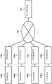
Fig. 1 is a block diagram showing an example of a system arrangement;
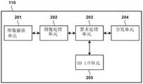
fig. 2 is a block diagram showing an example of a hardware arrangement of an image capturing apparatus;
fig. 3 is a block diagram showing an example of a functional arrangement of an image capturing apparatus;
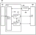
fig. 4 is a block diagram showing an example of a hardware arrangement of a detachable device;
fig. 5 is a block diagram showing an example of a functional arrangement of a detachable device;
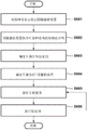
fig. 6 is a flowchart showing an example of a processing procedure performed by the system;
FIG. 7 is a flow chart illustrating an example of a process for determining which analytics processing may be performed;
fig. 8 is a flowchart showing an example of a processing procedure of determining the content of the analysis processing;
fig. 9 is a flowchart showing an example of a control procedure of executing the analysis processing;
fig. 10 is a flowchart showing an example of a control procedure of executing the post-processing;
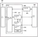
fig. 11 is a block diagram showing an example of a hardware arrangement of a detachable device according to a modification;
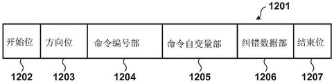
fig. 12A and 12B are views showing the structure of commands and responses;
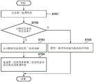
fig. 13 is a flowchart showing an example of a procedure of the result acquisition processing in consideration of a case where the processing is not completed.
Detailed Description
The embodiments will be described in detail below with reference to the accompanying drawings. It is noted that the following examples are not intended to limit the scope of the claimed invention. A plurality of features are described in the embodiments, but the invention which requires all of such features is not limited, and a plurality of such features may be combined as appropriate. Further, in the drawings, the same reference numerals are given to the same or similar configurations, and the repetitive description thereof is omitted.
< System arrangement >
Fig. 1 shows an example of the arrangement of an image analysis system according to this embodiment. As an example, a case where the system is a specific person tracking system will be described below. However, the present invention is not limited thereto, and the following demonstration may be applied to any system for analyzing an image and performing predetermined information output. The system is configured to include image capturing devices 110a to 110d, a network 120, and an input/output device 130. Note that each of the image capturing apparatuses 110a to 110d includes a slot of an apparatus capable of recording/recording, for example, an image to/from which can be attached/detached, and when the detachable apparatus 100a to 100d is inserted into the slot, the image capturing apparatus 110a to 110d is connected to the detachable apparatus 100a to 100 d. Note that the detachable apparatuses 100a to 100d are hereinafter referred to as "detachable apparatuses 100", and the image capturing devices 110a to 110d are hereinafter referred to as "image capturing devices 110".
The detachable device 100 is an arithmetic device attachable/detachable to/from the image capturing apparatus 110. As an example, the detachable device 100 is a device in which a predetermined processing circuit is mounted in an SD card. The detachable device 100 is configured to be inserted into the image capturing apparatus 110 as a whole in the form of, for example, an SD card, and thus may be configured to be connectable to the image capturing apparatus 110 without any portion protruding from the image capturing apparatus 110. Alternatively, the detachable device 100 may be configured so that, for example, half or more thereof may be inserted into the image capturing apparatus 110, and thus may be configured to be connectable to the image capturing apparatus 110 while causing a portion to slightly protrude from the image capturing apparatus 110. This can prevent the detachable apparatus 100 from being disturbed by an obstacle such as a wire and improve convenience in using the apparatus. In addition, since SD card slots are prepared in many existing image capturing apparatuses 110 (such as web cameras), the detachable device 100 can provide extended functions to the existing image capturing apparatuses 110. Note that the detachable device 100 may be configured to be mounted to the image capturing apparatus 110 via any interface used when mounting a storage device capable of storing at least an image captured by the image capturing apparatus 110, other than the form of an SD card. For example, the detachable device 100 may include a USB (universal serial bus) interface and may be configured to be mounted to a USB socket of the image capturing apparatus 110. The predetermined processing circuit is realized by, for example, an FPGA (field programmable gate array) programmed to perform predetermined processing, but may be realized in another form.
The image capturing apparatus 110 is an image capturing apparatus such as a web camera. In the present embodiment, the image capturing apparatus 110 contains an arithmetic apparatus capable of processing video, but is not limited thereto. For example, there may be an external computer such as a PC (personal computer) connected to the image capturing apparatus 110, and the combination may be handled as the image capturing apparatus 110. Further, in the present embodiment, the detachable apparatus 100 is installed in all the image capturing devices 110. Note that fig. 1 shows four image capturing apparatuses 110 and detachable devices mounted to these image capturing apparatuses 110. The number of combinations of devices may be three or less, or five or more. When the detachable apparatus 100 having the image analysis processing function is attached to the image capturing apparatus 110, video processing can be performed on the image capturing apparatus 110 side even if the image capturing apparatus 110 does not have the image analysis processing function. Further, as in the present embodiment, in the form in which an arithmetic device for video processing is arranged in the image capturing apparatus 110, by mounting the detachable device 100 including the arithmetic device in the image capturing apparatus 110, it is possible to diversify/complicate image processing executable on the image capturing apparatus 110 side.
The input/output device 130 is a device that performs accepting input from a user and outputting information (e.g., displaying information) to the user. In the present embodiment, the input/output device 130 is a computer such as a PC, for example, and performs information input/output when a browser installed in the computer or a processor incorporated in a local application performs information input/output.
The image capture device 110 and the input/output device 130 are communicatively connected via a network 120. Network 120 is configured to include a network such as Ethernet A plurality of routers, switches, cables, etc. of the communication standard. In the present embodiment, the
 network 120 may be any network that enables communication between the image capturing apparatus 110 and the input/output apparatus 130, and may be constructed by any scale and arrangement and communication standards to be complied with. For example, the network 120 may be the internet, a wired LAN (local area network), a wireless LAN, a WAN (wide area network), and the like. The Network 120 may be configured such that communication is possible, for example, through a communication protocol conforming to the ONVIF (Open Network Video Interface Forum) standard. However, the network 120 is not limited thereto, and may be configured such that, for example, communication by another communication protocol (such as a unique communication protocol) is possible.
< arrangement of apparatus >
(arrangement of image capturing apparatus)
The arrangement of the image capturing apparatus 110 will be described next. Fig. 2 is a block diagram showing an example of the hardware arrangement of the image capturing apparatus 110. As a hardware arrangement, the image capturing apparatus 110 includes, for example, an image capturing unit 201, an image processing unit 202, an arithmetic processing unit 203, a distribution unit 204, and an SD I/F unit 205. Note that I/F is an abbreviation of interface.
The image capturing unit 201 is configured to include: a lens section configured to form an image of light; and an image capturing element that performs analog signal conversion according to the formed image of the light. The lens unit has a zoom function for adjusting an angle of view, a stop function for adjusting a light amount, and the like. The image capturing element has a gain function of adjusting sensitivity in converting light into an analog signal. These functions are adjusted based on the setting values notified from the image processing unit 202. An analog signal obtained by the image capturing unit 201 is converted into a digital signal by an analog-to-digital conversion circuit, and is transmitted to the image processing unit 202 as an image signal.
The image processing unit 202 is configured to include an image processing engine and its peripheral devices. The peripheral devices include, for example, RAM (random access memory), drivers of I/F, and the like. The image processing unit 202 performs image processing such as development processing, filter processing, sensor correction, and noise removal, for example, on the image signal obtained from the image capturing unit 201, thereby generating image data. The image processing unit 202 can also transmit the setting values to the lens section and the image capturing element, and perform exposure adjustment to obtain an appropriate exposure image. The image data generated by the image processing unit 202 is transferred to the arithmetic processing unit 203.
The arithmetic processing unit 203 is formed of at least one processor such as a CPU or MPU, a memory such as a RAM and a ROM, a driver of an I/F, and the like. Note that the CPU is an acronym for a central processing unit, the MPU is an acronym for a microprocessing unit, the RAM is an acronym for a random access memory, and the ROM is an acronym for a read only memory. In an example, the arithmetic processing unit 203 may determine assignment of each part of processing to be performed in the above-described system as to which one of the image capturing apparatus 110 and the detachable device 100 should be performed, and perform processing corresponding to the assignment. Details of the processing contents and the processing assignment will be described later. The image received from the image processing unit 202 is transferred to the distribution unit 204 or the SD I/F unit 205. The data of the processing result or the processing status is also transmitted to the distribution unit 204.
The distribution unit 204 is configured to include a network distribution engine and peripheral devices such as, for example, RAM and ETH PHY modules. The ETH PHY module is a module that performs processing of a Physical (PHY) layer of the ethernet. The distribution unit 204 converts the image data or the data of the processing result or the processing state obtained from the arithmetic processing unit 203 into a format distributable to the network 120, and outputs the converted data to the network 120. The SD I/F unit 205 is an interface section for connecting the detachable device 100, and is configured to include, for example, a power supply and a mounting section such as an attachment/detachment socket for attaching/detaching the detachable device 100. Here, the SD I/F unit 205 is configured according to the SD standard established by the SD association. Communication between the detachable device 100 and the image capturing apparatus 110, such as transfer of an image obtained from the arithmetic processing unit 203 to the detachable device 100 or transfer of data obtained from the detachable device 100, is performed via the SD I/F unit 205.
Fig. 3 shows an example of the functional arrangement of the image capturing apparatus 110. The image capturing apparatus 110 includes, for example, an image capturing control unit 301, a signal processing unit 302, a storage unit 303, a control unit 304, an analysis unit 305, a device communication unit 306, and a network communication unit 307 as functions thereof.
The image capturing control unit 301 performs control of capturing the peripheral environment via the image capturing unit 201. The signal processing unit 302 performs predetermined processing on the image captured by the image capture control unit 301, thereby generating data of the captured image. The data of the captured image will be simply referred to as "captured image" hereinafter. The signal processing unit 302 encodes, for example, an image captured by the image capture control unit 301. The signal processing unit 302 performs encoding on the still image using, for example, an encoding method such as JPEG (joint photographic experts group). The signal processing unit 302 performs encoding on a moving image using an encoding method such as h.264/MPEG-4AVC (which will be referred to as "h.264" hereinafter) or HEVC (high efficiency video coding). The signal processing unit 302 may encode an image using an encoding method selected by a user from a plurality of encoding methods set in advance via, for example, an operation unit (not shown) of the image capturing apparatus 110.
The storage unit 303 stores a list of analysis processes that the analysis unit 305 can perform (will be referred to as a "first process list" hereinafter) and a list of post-processes for the results of the analysis processes. The storage unit 303 also stores the result of analysis processing described later. Note that, in the present embodiment, the processing to be executed is analysis processing. However, any processing may be performed, and the storage unit 303 may store a first processing list and a list of post-processing with respect to processing associated with processing to be performed. The control unit 304 controls the signal processing unit 302, the storage unit 303, the analysis unit 305, the device communication unit 306, and the network communication unit 307 to perform predetermined processing.
The analysis unit 305 selectively performs at least one of pre-analysis processing, and post-analysis processing, which will be described later, with respect to the captured image. The pre-analysis processing is processing performed on a captured image before analysis processing to be described later is performed. In the pre-analysis processing according to the present embodiment, as an example, processing of segmenting a captured image to create a segmented image is performed. The analysis processing is processing of outputting information obtained by analyzing an input image. In the analysis processing according to the present embodiment, as an example, the following processing is performed: the method includes receiving a segmented image obtained by pre-analysis processing, performing at least one of human body detection processing, face detection processing, and vehicle detection processing, and outputting an analysis processing result. The analysis process may be a process configured to output the position of the object in the segmented image using a machine learning model that has learned to use, for example, "YOLO 9000: techniques in Better Faster Stronger "Computer Vision and Pattern Recognition (CVPR)2016 to detect objects included in images. The post-analysis processing is processing to be executed after the analysis processing is executed. In the post-analysis processing according to the present embodiment, as an example, the following processing is performed: a value obtained by adding up the number of objects detected in the divided images based on the analysis processing result for each divided image is output as a processing result. Note that the analysis processing may be processing of detecting an object in an image by performing pattern matching and outputting the position of the object.
The device communication unit 306 performs communication with the detachable device 100. The device communication unit 306 converts the input data into a format processable by the detachable device 100 and transmits the data obtained by the conversion to the detachable device 100. In addition, the device communication unit 306 receives data from the detachable device 100 and converts the received data into a format that can be processed by the image capturing apparatus 110. In the present embodiment, as the conversion processing, the device communication unit 306 performs processing of converting a decimal (decimal) between a floating-point format and a fixed-point format. However, the present invention is not limited thereto, and another process may be performed by the device communication unit 306. Further, in the present embodiment, the device communication unit 306 transmits a command sequence predetermined within the range of the SD standard to the detachable device 100, and receives a response from the detachable device 100, thereby performing communication with the detachable device 100. The network communication unit 307 performs communication with the input/output device 130 via the network 120.
(arrangement of removable device)
Fig. 4 is a block diagram showing an example of the hardware arrangement of the detachable device 100. By way of example, the detachable device 100 is configured to include an I/F unit 401, an FPGA 402, an SD controller 403, and a storage unit 404. The detachable apparatus 100 is formed in a shape that can be inserted into/removed from an attachment/detachment socket of the SD I/F unit 205 provided in the image capturing device 110, that is, a shape conforming to the SD standard.
The I/F unit 401 is an interface section for connecting an apparatus such as the image capturing apparatus 110 with the detachable device 100. The I/F unit 401 is configured to include, for example, an electrical contact terminal that receives power supply from the image capturing apparatus 110 and generates and distributes power or the like to be used in the detachable device 100. As for items defined in (compliant with) the SD standard, the I/F unit 401 is compliant as with the SD I/F unit 205 of the image capturing apparatus 110. The reception of the image and setting data from the image capturing apparatus 110 and the transmission of data from the FPGA 402 to the image capturing apparatus 110 are performed via the I/F unit 401.
The FPGA 402 is configured to include an input/output control unit 410, a process switching unit 411, and an arithmetic processing unit 412. The FPGA 402 is a semiconductor device that is capable of repeatedly reconstructing internal logic circuit structures. Processing functions may be added (provided) to the apparatus in which the detachable device 100 is mounted through processing implemented by the FPGA 402. Further, since the logic circuit configuration can be changed later by the reconfiguration function of the FPGA 402, when the detachable device 100 is installed in, for example, an apparatus in a rapidly developing technical field, appropriate processing can be performed in the apparatus at an appropriate timing. Note that, in the present embodiment, an example using an FPGA will be described. However, a general-purpose ASIC or a dedicated LSI may be used, for example, as long as the processing described later can be performed. The FPGA 402 is activated by writing setting data including information of a logic circuit configuration to be generated from the dedicated I/F or reading out the setting data from the dedicated I/F. In the present embodiment, the setting data is held in the storage unit 404. When powered on, the FPGA 402 reads out setting data from the storage unit 404, and generates and activates logic circuits. However, the present invention is not limited thereto. For example, the image capturing apparatus 110 can write setting data into the FPGA 402 via the I/F unit 401 by implementing a dedicated circuit in a detachable device.
The input/output control unit 410 is configured to include a circuit for transmitting/receiving an image to/from the image capturing apparatus 110, a circuit for analyzing a command received from the image capturing apparatus 110, a circuit for performing control based on the result of the analysis, and the like. The commands herein are defined by the SD standard, and some of them may be detected by the input/output control unit 410. Details of the function will be described later. The input/output control unit 410 controls to send the image to the SD controller 403 in the storage process, and to send the image to the arithmetic processing unit 412 in the image analysis process. If the setting data of the process switching is received, the input/output control unit 410 transmits the setting data to the process switching unit 411. The process switching unit 411 is configured to include the following circuits: the circuit is configured to obtain information of the image analysis processing function from the storage unit 404 based on the setting data received from the image capturing apparatus 110 and write the information into the arithmetic processing unit 412. The information of the image analysis processing function includes setting parameters indicating, for example, the order and type of operations processed in the arithmetic processing unit 412, the coefficients of the operations, and the like. The arithmetic processing unit 412 is configured to include a plurality of arithmetic circuits required to perform an image analysis processing function. The arithmetic processing unit 412 performs each arithmetic processing, transmits the processing result to the image capturing apparatus 110, and/or records the processing result in the storage unit 404 based on the information of the image analysis processing function received from the processing switching unit 411. As described above, the FPGA 402 extracts the setting data of the execution target processing function included in the setting data corresponding to the plurality of processing functions held in advance, and rewrites the processing content to be executed by the arithmetic processing unit 412 based on the extracted setting data. This allows the detachable device 100 to selectively perform at least one of a plurality of processing functions. In addition, by appropriately adding the setting data of the processing to be newly added, the latest processing can be performed on the image capturing apparatus 110 side. Note that, hereinafter, holding a plurality of setting data corresponding to a plurality of processing functions will be referred to as holding a plurality of processing functions. That is, even in a state where the FPGA 402 of the detachable device 100 is configured to execute one processing function, if the processing content of the arithmetic processing unit 412 can be changed by the setting data of another processing function, this will be expressed as holding a plurality of processing functions.
The SD controller 403 is a known control IC (integrated circuit) as defined by the SD standard, and performs control of slave operations of the SD protocol and control of data read/write of the memory unit 404. The storage unit 404 is formed of, for example, a NAND flash memory, and stores various information such as storage data written from the image capturing apparatus 110, information of an image analysis processing function written in the arithmetic processing unit 412, and setting data of the FPGA 402.
Fig. 5 shows an example of the functional arrangement of the detachable device 100. The detachable device 100 comprises as its functional arrangement, for example, an analyzing unit 501, a communication unit 502 and a storage unit 503. The analysis unit 501 performs analysis processing on the image. For example, if an analysis processing setting request is input, the analysis unit 501 performs setting to set the input analysis processing to an executable state. If an image is input, the analysis unit 501 performs analysis processing set to an executable state on the input image. In the present embodiment, the executable analysis processing includes a human body detection processing and a face detection processing, but is not limited to these. For example, it may be a process of determining whether a person stored in advance is included in an image (face authentication process). For example, if the degree of matching between the image feature amount of a person stored in advance and the image feature amount of a person detected from an input image is calculated and is equal to or greater than a threshold value, it is determined that the person is a person stored in advance. Alternatively, it may be a process of superimposing a predetermined mask image on a person detected from an input image or performing mosaic processing for the purpose of privacy protection. It may be a process of detecting whether or not a person in an image is taking a specific action using a learning model in which the specific action of the person has been learned by machine learning. Further, it may be a process of determining which region is in the image. It may be a process of determining which region is a region in an image using a learning model that has been learned to a building, a road, a person, a sky, or the like, for example, through machine learning. As described above, the executable analysis process can be applied to both the image analysis process using machine learning and the image analysis process not using machine learning. Each of the analysis processes described above may not be performed independently by the detachable device 100 but performed in cooperation with the image capturing apparatus 110. The communication unit 502 performs communication with the image capturing apparatus 110 via the I/F unit 401. The storage unit 503 stores setting contents such as analysis processing and information for time required for the analysis processing. The time required for the analysis processing is, for example, an actual time required when predetermined processing is executed, and may be a time at which the analysis processing is guaranteed to end by a waiting time. Alternatively, the time required for the analysis processing may be the number of clock cycles processed in the analysis processing. Note that time information may be stored separately for each analysis process. In addition, the time required for the analysis processing may be set to, for example, a sufficiently large initial value, the time required when the processing is actually executed may be collected as a statistical value, and the initial value may be updated based on the collected value.
< treatment Process >
Next, an example of a process performed in the system will be described. Note that the processing executed by the image capturing apparatus 110 in the following processing is realized, for example, by a processor in the arithmetic processing unit 203 executing a program or the like stored in a memory. However, this is merely an example, and the processing described later may be partially or entirely implemented by dedicated hardware. In addition, the processing performed by the detachable apparatus 100 or the input/output device 130 may also be realized by a processor in each device executing a program or the like stored in a memory, and the processing may be partly or entirely realized by dedicated hardware.
(Overall Process)
Fig. 6 schematically shows a series of processes of image analysis processing performed by the system. In this process, first, the user mounts the detachable device 100 to the image capturing apparatus 110 (step S601). The image capturing apparatus 110 performs an initialization sequence of the detachable device 100 (step S602). In this initialization sequence, a predetermined command is transmitted/received between the image capturing apparatus 110 and the detachable device 100, and thus the image capturing apparatus 110 is set to a state in which it can use the detachable device 100. Thereafter, the image capturing apparatus 110 determines which processes can be performed by the detachable device 100, and determines which processes can be performed locally (may be performed only by the image capturing apparatus 110 or by a combination of the image capturing apparatus 110 and the detachable device 100) (step S603). Note that although the detachable device 100 may be configured to perform any processing, processing unrelated to processing that should be performed on the image capturing apparatus 110 side need not be taken into consideration. In an example, the image capture device 110 may maintain a list of executable processes previously obtained from, for example, the input/output device 130. In this case, when information indicating a process executable by the detachable device 100 is obtained from the detachable device 100, the image capturing apparatus 110 may determine the executable process according to whether the process is included in the list. Next, the image capturing apparatus 110 determines a process to be performed, and performs setting of the detachable device 100 as necessary (step S604). That is, if at least a part of the processing determined as the execution target is to be executed by the detachable device 100, the setting of the detachable device 100 for the processing is executed. In this setting, for example, reconfiguration of the FPGA 402 can be performed using setting data corresponding to processing of an execution target. Then, the image capturing apparatus 110 or the detachable device 100 performs an analysis process (step S605). After that, the image capturing apparatus 110 performs post-processing (step S606). Note that the processing of steps S605 and S606 is repeatedly performed. The process shown in fig. 6 is performed when, for example, the detachable device 100 is mounted. However, at least a part of the processing shown in fig. 6 may be repeatedly performed so that, for example, the processing of step S603 is performed again when the detachable device 100 is detached.
(processing for determining which processing can be performed)
Fig. 7 shows an example of a process procedure of determining which processes the image capturing apparatus 110 can perform. This process corresponds to the process of step S603 in fig. 6, and may be executed if a device such as the detachable device 100 is mounted on the image capturing apparatus 110 or removed, or if the image capturing apparatus 110 is powered on. In this process, the image capturing apparatus 110 reads out the process executable by the detachable device 100, integrates it with the analysis process executable by the image capturing apparatus 110 itself, and determines which analysis processes are executable on the image capturing apparatus 110 side.
First, the control unit 304 of the image capturing apparatus 110 reads out a first processing list stored in the storage unit 303, the first processing list being a processing list executable by the analysis unit 305 of the image capturing apparatus 110 itself (step S701). Next, the control unit 304 determines whether the mounted apparatus is, for example, a conventional apparatus having only a storage function or a predetermined apparatus having a specific processing function such as the detachable apparatus 100 (step S702). For example, the control unit 304 controls the device communication unit 306 to issue a read request (read command) for a specific address to the mounted device and read out the tag data stored at the specific address. The control unit 304 may determine whether the detachable device 100 is a predetermined device having a specific processing function based on the read flag data. However, this is merely an example, and whether the installed device is a predetermined device may be determined by another method.
If the mounted apparatus is a predetermined apparatus (yes in step S702), the control unit 304 executes processing for determining which processing can be executed in the apparatus (detachable apparatus 100). The control unit 304 controls the device communication unit 306 to communicate with the detachable device 100, and obtains a list of processes executable in the detachable device 100 (which will be referred to as a "second process list" hereinafter) (step S703). For example, as in the case of determining whether the detachable device 100 is a predetermined device, the control unit 304 reads out data stored at a specific address, thereby obtaining a second processing list. Note that, for example, the second processing list may be stored at the same address as flag data for determining whether or not the detachable device is a predetermined device. In this case, the image capturing apparatus 110 can simultaneously execute the processing of step S702 and the processing of step S703 by accessing the address and obtaining the flag data and the second processing list at the same time. However, the present invention is not limited thereto, and these data may be stored at different addresses. After that, the control unit 304 creates an integrated processing list in which the first processing list of the processing executable by the image capturing apparatus 110 itself read out from the storage unit 303 and the second processing list obtained from the detachable device are integrated (step S704), and ends the processing.
The integrated process list represents a list of processes that can be locally performed on the image capturing apparatus 110 side without the apparatus such as a server apparatus on the network performing the processes. Note that, in the present embodiment, the integrated processing list is a list obtained by a union of the processing included in the first processing list and the processing included in the second processing list. The integrated processing list is a list of processes included in at least one of the first processing list and the second processing list. However, the present invention is not limited thereto. For example, if another process can be executed by combining the processes included in the first process list and the processes included in the second process list, another executable process may be added to the integrated process list.
If the installed device is not a predetermined device (no in step S702), the control unit 304 determines that there is no process executable by the installed device. Therefore, the control unit 304 sets the first process list of the processes executable by the own apparatus read out from the storage unit 303 as an integrated process list representing the processes executable locally on the image capturing apparatus 110 side (step S705), and ends the process. Note that when the processing shown in fig. 7 is executed at the time of device removal, of course, a predetermined device is not installed, and therefore, the first processing list is processed as an integrated processing list.
This makes it possible to form a list of processes locally executable on the image capturing apparatus 110 side based on whether or not the detachable device 100 capable of executing a specific process is mounted in the image capturing apparatus 110. In addition, when presenting the integrated process list to the user, as will be described later, the user can select a process locally executable on the image capturing apparatus 110 side by the installation of the detachable device 100.
(processing for determining content of analysis processing)
Fig. 8 shows an example of a processing procedure of determining analysis processing contents by the image capturing apparatus 110. In this process, the analysis process locally executable on the image capturing apparatus 110 side is presented to the user via the input/output apparatus 130, and the input/output apparatus 130 accepts the selection of the user. The image capturing apparatus 110 determines the analysis processing to be performed according to the information representing the user selection accepted via the input/output apparatus 130.
In this process, first, the input/output device 130 performs communication with the image capturing device 110, and requests the captured image, the integrated processing list, and the post-processing list to be obtained (step S801). As an example, the input/output device 130 transmits a request message defined by the ONVIF standard to the image capturing device 110, thereby requesting transmission of information to the image capturing device 110. However, the present invention is not limited thereto, and the information transmission request may be made through another message or the like. In the image capturing apparatus 110, based on the request, the image capturing control unit 301 captures the peripheral environment, and the control unit 304 controls the signal processing unit 302 to process the image captured by the image capturing control unit 301 and obtain a captured image (step S802). Note that the image capturing apparatus 110 may capture the peripheral environment regardless of the presence/absence of the request, and continuously obtain captured images. The image capture device 110 may store the captured image locally or transfer the captured image to another device, such as a network server, and store it. The control unit 304 reads out the post-processing list stored in the storage unit 303. In the present embodiment, the post-processing list includes display processing and storage processing, but is not limited thereto. The control unit 304 controls the network communication unit 307 to transmit the post-processing list, the integration processing list obtained by the processing shown in fig. 7, and the captured image obtained in step S802 to the input/output device 130 (step S803). As an example, the image capturing apparatus 110 transmits a response message to the request message defined by the above-described ONVIF standard to the input/output apparatus 130, thereby transmitting information to the input/output apparatus 130. However, the present invention is not limited thereto, and the information may be transmitted through another message or the like. Note that only the processing to be executed may be considered here, and the captured image request by the input/output apparatus 130 in step S801, the captured image acquisition in step S802, and the captured image transmission to the input/output apparatus 130 in step S803 may not be executed.
The input/output device 130 receives the captured image, the integrated processing list, and the post-processing list from the image capture device 110. The input/output device 130 presents the integrated processing list and the post-processing list to the user through a screen display or the like (step S804). Note that at this time, the input/output device 130 may also present the captured image to the user through a screen display or the like. After that, the user confirms the displayed integration processing list and post-processing list, and selects analysis processing to be executed (which will be referred to as "execution target processing" hereinafter) from the integration processing list (step S805). In addition, the user selects post-processing to be executed (which will be referred to as "execution target post-processing" hereinafter) (step S806). The input/output device 130 transmits information indicating the selection result of the execution target process and the execution target post-process to the image capturing device 110 (step S807).
The control unit 304 of the image capturing apparatus 110 controls the network communication unit 307 to receive information indicating the execution target process selected by the user from the input/output apparatus 130, and determines whether the execution target process is a process included in the second process list (step S808). If the execution target process is not included in the second processing list (no in step S808), the control unit 304 ends the process shown in fig. 8 without notifying the detachable device 100 of the execution of the process in the image capturing apparatus 110. On the other hand, if the execution target process is included in the second process list (yes in step S808), the control unit 304 controls the device communication unit 306 to transmit an execution target process setting request to the detachable device 100 (step S809).
The communication unit 502 of the detachable device 100 receives an execution target process setting request from the image capturing apparatus 110. The communication unit 502 outputs the execution target process setting request received from the image capturing apparatus 110 to the analysis unit 501. Based on the execution target process setting request input from the communication unit 502, the analysis unit 501 acquires the setting of the execution target process from the storage unit 503, and executes the setting to set the detachable device 100 in a state in which the execution target process can be executed (step S810). For example, after the setting processing is completed, the communication unit 502 transmits a setting completion notification to the image capturing apparatus 110 (step S811). Note that the communication unit 502 only needs to notify information for prohibiting the image capturing apparatus 110 from writing data at the timing when the setting of the detachable device 100 has not been completed yet, and may notify the image capturing apparatus 110 of information of the setting completion timing and the like before the setting is actually completed. The control unit 304 of the image capturing apparatus 110 controls the device communication unit 306 to receive a setting completion notification from the detachable device 100.
The setting completion notification from the detachable device 100 to the image capturing apparatus 110 may be performed using, for example, one of the following three methods. In the first notification method, the communication unit 502 outputs a BUSY signal in a case where the setting of executing the target processing has not ended yet at the time of the write processing of the data of the first block from the image capturing apparatus 110. The output of the BUSY signal is performed by, for example, driving a signal line of DATA defined by the SD standard to a low state. In this case, the image capturing apparatus 110 confirms the BUSY signal, thereby discriminating whether the setting of executing the target process is completed. In the second notification method, the time until the setting of executing the target process is completed is stored in advance at the above-described specific address, and the image capturing apparatus 110 reads out information of the time until the setting is completed. After the time until the execution target process setting is completed has elapsed, the image capturing apparatus 110 outputs the write data (issues a write command). This allows the image capturing apparatus 110 to transmit the data of the captured image after the setting to execute the target process is completed. In the third notification method, when the setting of the execution target process is completed, the analysis unit 501 writes a setting completion flag at the second specific address of the detachable apparatus 100. The image capturing apparatus 110 reads out the data at the second specific address, thereby discriminating whether the setting of executing the target process is completed. Note that the information of the address at which the setting completion flag is written may be stored at the above-described specific address, or may be stored at another address.
(execution control of analysis processing)
Fig. 9 shows an example of a control procedure when the image capturing apparatus 110 performs analysis processing. In this process, first, the image capture control unit 301 captures a peripheral environment (step S901). The control unit 304 controls the signal processing unit 302 to process the image captured by the image capture control unit 301 and obtain a captured image. After that, the control unit 304 controls the analysis unit 305 to perform pre-analysis processing on the captured image input from the control unit 304, and obtains an image of a result of the pre-analysis processing (step S902). The control unit 304 determines whether the execution target process is included in the second process list (step S903).
After determining that the execution target process is not included in the second processing list (no in step S903), the control unit 304 controls the analysis unit 305 to execute the execution target process on the image of the analysis pre-processing result in the image capturing apparatus 110 (step S904). The control unit 304 controls the analysis unit 305 to perform post-analysis processing on the analysis processing result (step S913), and ends the processing.
If the execution target process is included in the second process list (yes in step S903), the control unit 304 controls the device communication unit 306 to request an analysis processing time, which is a time from the execution target process execution request to the completion of the process, from the detachable device 100 (step S905). Note that the analysis processing time is sometimes referred to as "processing time" hereinafter. Upon receiving the processing time request, the communication unit 502 of the detachable device 100 transmits the information of the processing time read out from the storage unit 503 to the image capturing device 110 (step S906). Note that, in the present embodiment, for example, information of the processing time may be stored at an address that the control unit 304 has accessed in step S702 to determine whether the detachable device 100 is a predetermined device. Note that information of the processing time may be stored in another address of the storage unit 503. For example, the control unit 304 of the image capturing apparatus 110 may transmit a read request (read command) to an address storing information of the processing time and obtain the information of the processing time as a response to the request. Information of the processing time is stored for each process, and the image capturing apparatus 110 is notified of the processing time associated with the execution target process specified by the image capturing apparatus 110.
Alternatively, for example, the processing time may be calculated as the product N/(f × k) of the operating frequency f, the multiplier value k (e.g., by a phase-locked loop circuit (PLL)), and the number N of clock cycles from the request to the end of the analysis processing. In one example, if the operating frequency f is 5MHz, k is 2, and N is 100,000, then 105/(5×106×2)=10-2[ second of]And the processing time is calculated as 10 milliseconds. For example, as the information indicating the performance, the control unit 304 may obtain the information of the operating frequency by reading out the information stored in the storage unit 503 or from the arithmetic processing unit 203 of the hardware. Note that, for example, in step S906, or for example, when the detachable device 100 is mounted in the image capturing apparatus 110, information of the operating frequency of the arithmetic processing unit 412 of the detachable device 100 may be notified to the image capturing apparatus 110. In addition, for example, as the information indicating the performance, the control unit 304 mayTo obtain the multiplier value k by reading out the information stored in the storage unit 503 or, for example, from a phase-locked loop circuit of the hardware of the detachable apparatus 100. For example, the number of clock cycles of the analysis processing is stored in the storage unit 503 in association with the analysis processing, and the control unit 304 may acquire the number of clock cycles corresponding to the execution target processing from the storage unit 503. In this way, in step S906, the detachable device 100 notifies the image capturing apparatus 110 of information having an arbitrary format, and is able to specify a processing time to execute the target processing.
In addition, when one or more divided images are input to the detachable device 100 and predetermined analysis processing is immediately performed using the one or more divided images, the detachable device 100 may notify the image capturing apparatus 110 of information capable of specifying a processing time of each divided image. For example, the detachable device 100 may notify the image capturing apparatus 110 of the value T as the processing time of one divided image. In this case, the image capturing apparatus 110 may specify dT obtained by multiplying the number d of divided images by the notified processing time T as a time until the entire processing is completed. Note that the divided image or images to be immediately processed may be a part or all of the images obtained by image capturing. That is, the processing may be performed immediately on one or more divided images constituting some of the images obtained by image capturing, or may be performed immediately on a plurality of divided images constituting all of the obtained images. In this case, the number of divided images targeted for batch processing is specified as the number d of divided images described above. Alternatively, for example, when the process of integrating the processing results is performed after the process of each divided image, the detachable device 100 may also notify the image capturing apparatus 110 of the processing time T0 such as integration. In this case, the image capturing apparatus 110 may designate, for example, a time until the entire process is completed as dT + T0. In addition, the image capturing apparatus 110 may be notified of information of the number of clock cycles of each of the processes of dividing the image or the processes such as integration. Note that, for example, when a plurality of processes are executed continuously, information capable of specifying a processing time until each of the plurality of processes is completed or a processing time until all of the plurality of processes is completed may be notified to the image capturing apparatus 110. In any case, the image capturing apparatus 110 obtains information capable of specifying a processing time until the completion of the entire processing performed by the detachable device 100. Then, the image capturing apparatus 110 performs calculation and specifies a processing time as needed.
After that, the control unit 304 controls the device communication unit 306 to transmit the analysis pre-processing result to the detachable device 100 (step S907). For example, the control unit 304 issues a write request (write command) of the pre-analysis processing result, thereby transmitting an image of the pre-analysis processing result to the detachable device 100. The control unit 304 controls the device communication unit 306 to transmit an execution target process request to the detachable device 100 (step S908). In the image capturing apparatus 110, the control unit 304 stops the processing and waits for the length of the processing time specified based on the information obtained from the detachable device 100 (step S909). On the other hand, in the detachable device 100, the communication unit 502 outputs the image of the analysis pre-processing result received in step S907 to the analysis unit 501, and the analysis unit 501 performs the execution target process set in step S810 of fig. 8 on the image (step S910). The analysis unit 501 stores the processing result in the storage unit 503, for example, in an address assigned to each process.
After the processing time has elapsed, the control unit 304 resumes the processing. Then, the control unit 304 controls the device communication unit 306 to request the analysis processing result of the detachable device 100 (step S911), and the communication unit 502 of the detachable device 100 notifies the image capturing apparatus 110 of information indicating the result (step S912). For example, the control unit 304 controls the device communication unit 306 to issue a read request (read command) to an address storing the analysis processing result, and to obtain information of the processing result stored at the address. Thereafter, the control unit 304 of the image capturing apparatus 110 controls the device communication unit 306 to receive the analysis processing result from the detachable device 100. After that, the control unit 304 controls the analysis unit 305 to execute post-analysis processing for analyzing the processing result (step S913).
(execution control of post-processing)
Fig. 10 shows an example of a control procedure when the image capturing apparatus 110 performs post-processing. In this process, the control unit 304 of the image capturing apparatus 110 determines whether "display" is included in the execution target post-process (step S1001). After determining that the display is included in the execution target post-processing (yes in step S1001), the control unit 304 controls the network communication unit 307 to transmit the result of the analysis processing to the input/output device 130 (step S1002). The input/output device 130 receives the result of the analysis processing from the image capturing device 110, and then presents the result of the analysis processing to the user through a screen display or the like (step S1003). On the other hand, if the control unit 304 determines that the display is not included in the execution target post-processing (no in step S1001), the processing of steps S1002 and S1003 is not performed.
In addition, the control unit 304 of the image capturing apparatus 110 determines whether "storage" is included in the execution of the target post-processing (step S1004). Note that the determination of step S1004 may be performed before step S1001, or may be performed in parallel with step S1001. After determining that the storage is included in the execution target post-processing (yes in step S1004), the control unit 304 controls the storage unit 303 to store the result of the analysis processing and ends the processing. On the other hand, after determining that storage is not included in the execution target post-processing (no in step S1004), the control unit 304 ends the processing without executing the processing of step S1005.
As described above, according to the selected post-processing, the image capturing apparatus 110 can perform transmission of the result of the analysis processing to the input/output apparatus 130 or storage in the storage unit 303 without accepting a special setting operation by the user, and the convenience is improved.
In the present embodiment, as described above, when the detachable device 100 is caused to partially or entirely perform the analysis processing, the image capturing apparatus 110 obtains the processing time (by performing calculation or the like as needed) until the processing is completed after the execution request of the processing is issued. The image capturing apparatus 110 waits after inputting image data for processing (preprocessing result), and requests execution of processing until the obtained processing time elapses, and reads out the processing result after that. This allows the image capturing apparatus 110 to obtain the processing result at an appropriate timing in an arrangement in which the detachable device 100 cannot automatically output the processing result after the end of the processing. Since the processing result reading processing is executed, for example, immediately after the processing is completed (or after a sufficiently short time has elapsed after the processing is completed), the processing executed by the image capturing apparatus 110 and the detachable device 100 in cooperation can be accelerated. In addition, it is possible to prevent the image capturing apparatus 110 from attempting to obtain a processing result before the processing is completed, and to prevent unnecessary memory access.
Note that, in the present embodiment, the time from processing a request to completion of processing is defined as a processing time. However, for example, an elapsed time from a start point set as a timing of inputting processing target data (such as a preprocessing result of dividing an image) to completion of processing may be defined as a processing time. In this case, for example, the process of the transmission/reception process execution request in step S908 may not be executed, and the analysis process is automatically started in response to the input of the process target data. The image capturing apparatus 110 may transmit the processing target data to the detachable device 100, wait for a processing time from the completion of the transmission, and then read out the processing result. Since transmission/reception of the process execution instruction is omitted, the number of times of command transmission/reception can be reduced, and the processing efficiency can be improved. Note that in this form, it can be said that the processing target data write command is used as the processing execution request. That is, the process execution request command may be issued separately from the process target write command, or the process target write command may be used as the process execution request command. The timing of the command, but the timing of actually starting the process in the detachable device 100 may be set as the starting point, and the elapsed time from the timing to the completion of the process may be defined as the processing time. As described above, the elapsed time from the timing arbitrarily set in association with the start of processing to the completion of processing can be defined as the processing time.
In addition, in the present embodiment, when the image capturing apparatus 110 causes the detachable apparatus 100 to start processing, a processing time related to the processing is obtained. However, the present invention is not limited thereto. For example, when the detachable device 100 is mounted in the image capturing apparatus 110, information capable of specifying a processing time may be included in, for example, information to be read out by the image capturing apparatus 110 to determine whether the detachable device 100 is a predetermined device in step S702. Accordingly, the information only needs to be read once when the detachable device 100 is mounted. Therefore, the number of times of command transmission/reception can be reduced, and the processing efficiency can be improved.
In the above-described embodiments, the image analysis processing has been described as an example of the analysis processing. However, the present invention can also be applied to sound analysis processing. For example, the present invention can be applied to a process of detecting a sound pattern such as a screaming sound, a gunshot sound, or a glass breaking sound. For example, a feature amount of a sound is extracted by various sound data analysis methods (e.g., spectrum analysis) and compared with a detected sound pattern. By calculating the degree of matching, a particular sound pattern can be detected.
When the sound analysis processing is performed, the sound data is divided into sound data of a predetermined time, and the sound analysis processing is performed in units of the sound data of the predetermined time. In addition, the predetermined time is appropriately changed according to the sound pattern of the detection target. Accordingly, sound data of a time corresponding to the sound pattern to be detected is input to the detachable apparatus 100. The detachable apparatus 100 has a function of analyzing input sound data or a function of holding input sound data.
In the above-described embodiment, the detachable device 100 capable of non-temporarily storing data input from the image capturing apparatus 110 has been described as an example. However, in some embodiments, a detachable device 100 may be used that is not capable of non-temporarily storing data input from the image capture apparatus 110. That is, the detachable device 100 may perform analysis processing only on data input from the image capturing apparatus 110, and may store the data non-temporarily. In other words, the detachable device 100 is not intended to store data, as in the case of a normal SD card, but is used only for analysis processing.
< modification example >
In the above-described embodiments, the method of improving the efficiency when the detachable device 100 is caused to perform the processing in the case where the image capturing apparatus 110 can obtain the processing time in the detachable device 100 in advance has been described. On the other hand, the actual processing time in the detachable device 100 may be longer than the obtained processing time due to factors such as, for example, a voltage drop or an environment in which the image capturing apparatus 110 is arranged. If the actual processing time is long, the image capturing apparatus 110 may perform an attempt for the detachable device 100 to obtain a processing result before the execution of the target processing is completed. In this modification, if the actual processing time is longer than the obtained processing time, the processing result is obtained after the execution of the target processing is completed. The method will be described below.
Fig. 11 shows an example of the hardware arrangement of the detachable device 100 according to this embodiment. As shown in fig. 11, in the present embodiment, the arithmetic processing unit 412 includes a single or a plurality of calculation execution units 1101, and a single or a plurality of RAMs 1102. Each process executable by the detachable device 100 may be constructed in the following manner: for example, a plurality of partial processes are combined. Here, for example, at least some of the plurality of calculation execution units 1101 may be formed of circuits that perform different partial processes. Note that some of the calculation execution units 1101 may be configured to execute common partial processing in parallel for different data. The plurality of calculation execution units 1101 may be connected to each other, or may be connected to, for example, a RAM for temporary recording. Each partial process is associated with an index indicating the order of processing in the execution target process (the order of partial processes in the execution target process), a command indicating the type of operation to be executed, and a weight indicating the coefficient of operation to be executed. In this case, the indexes, commands, and weights associated with the partial processes are stored in the storage unit 404 and disposed on the RAM 1102. The calculation execution unit 1101 accesses the RAM1102 and obtains a command of the operation, thereby executing a corresponding partial process. However, the present invention is not limited thereto, and for example, there may be no partially processed index. In this case, the commands and weights of the operations are disposed on the RAM1102 according to the processing order.
(communication between the image capturing apparatus 110 and the detachable device 100)
The communication between the image capturing apparatus 110 and the detachable device 100 will be described here. The arithmetic processing unit 203 of the image capturing apparatus 110 and the SD controller 403 of the detachable device 100 are connected by a power line, a GND line, a clock line, a command line, and a data line via the device insertion socket of the SD I/F unit 205 of the image capturing apparatus 110. Note that the clock line, command line, and data line are connected via the FPGA 402. On the clock line, the synchronous clock output from the arithmetic processing unit 203 is transmitted. On the command line, a command issued for an operation request from the arithmetic processing unit 203 to the SD controller 403 and a response to the command from the SD controller 403 to the arithmetic processing unit 203 are transmitted. On the data line, the write data from the arithmetic processing unit 203 and the read data from the detachable device 100 are transferred. In addition, the arithmetic processing unit 203 discriminates high and low of a device detection signal of the SD I/F unit 205 that the device is inserted into the outlet, thereby recognizing whether or not the detachable device 100 is inserted.
After the power supply, the arithmetic processing unit 203 issues a command to the SD controller 403 on the command line. Upon receiving the response from the SD controller 403 and expressing the device information as output data of the SD card, the arithmetic processing unit 203 sets a voltage, a communication speed (clock frequency), and the like for data communication.
Fig. 12A and 12B show the structure of commands and responses transmitted on the command line. The commands and responses have a structure conforming to the SD standard. The command 1201 issued from the arithmetic processing unit 203 to the SD controller 403 is configured to include a command number section 1204, a command argument section 1205, and an error correction data section 1206. In the command number section 1204, a value indicating the type of the command is described. For example, if "23" is stored in the command number section 1204, this indicates that the command is a block count specifying command for specifying the number of data blocks. If a value of "25" is stored in the command number section 1204, this indicates that the command is a multiple write command. If "12" is stored in the command number section 1204, this indicates that the command is a data transfer stop command. In the command argument section 1205, information such as the number of transfer data blocks and the write/read address of the memory is specified according to the type of command. A command start bit 1202 indicating the start position of the command is added to the first bit of the command, and a command end bit 1207 indicating the end of the command is added to the last bit of the command. Further, a direction bit 1203 indicating that the command is a signal output from the image capturing apparatus 110 to the detachable device 100 is added after the command start bit 1202.
The response 1211 returned from the SD controller 403 in response to the command from the arithmetic processing unit 203 includes: a response number part 1214, a response argument part 1215, and an error correction data part 1216, the response number part 1214 indicating to which command the response is returned. A response start bit 1212 indicating the start position of the response is added to the first bit of the response, and a response end bit 1217 indicating the end position of the response is added to the last bit of the response. In addition, a direction bit 1213 indicating that the response is a signal output from the detachable device 100 to the image capturing apparatus 100 is also added after the response start bit 1212. In the response argument part 1215, an information item such as the state of the SD card is stored according to the command type.
A method of transmitting/receiving data between the arithmetic processing unit 203 and the detachable device 100 will be described below. In the SD I/F unit 205, data transfer is performed on a block basis in both data writing and reading.
The arithmetic processing unit 203 transfers data of a plurality of blocks to the detachable apparatus 100 using the following two methods. In the first method, after the number of blocks is specified by a block count specification command for transferring data, the specified number of block data is transferred by a multiple write command. In the block count designation command, the number of blocks of read data is designated by the command argument section 1205. In the multiple write command, the address of the memory cell 404 to which data is to be written is specified by the command argument portion 1205. In the second method, data transfer is started by issuing a multiple write command without issuing a block count designation command. When the data transfer is finished, a transfer stop command is issued, thereby ending the processing. At this time, the command argument portion 1205 of the multiple write command specifies only the address of the memory cell 404 on which data should be written. The arithmetic processing unit 203 can arbitrarily switch the two reading methods.
Note that when performing the storage processing, the FPGA 402 directly inputs the command and data sent from the arithmetic processing unit 203 to the SD controller 403, and the SD controller 403 stores the received data at the address of the storage unit 404 specified by the command. When performing image analysis processing, the FPGA 402 performs analysis processing on data sent from the arithmetic processing unit 203, and outputs data of a processing result and information for specifying a predetermined address of the storage unit 404 to the SD controller 403. The SD controller 403 stores the processing result at the designated address of the storage unit.
The arithmetic processing unit 203 reads out data of a plurality of blocks from the detachable apparatus 100 using the following two methods. In the first method, after the number of blocks is specified by the block count specifying command, a multiple read command is issued, and the specified number of block data is read. In the block count designation command, the number of blocks of read data is designated by the command argument section 1205. The command argument portion 1205 of the multiple read command specifies the address of the memory of the data read source. In the second method, data reading is started by issuing a multiple read command without issuing a block count designation command, and processing is ended by issuing a transfer stop command. The arithmetic processing unit 203 can arbitrarily switch the two reading methods.
Note that if the write data or the read data is data of one block, a single write command or a single read command is issued, so that the data write or read is performed without issuing a block count designation command and a transfer stop command. In the single write command and the single read command, as described above, the command argument section 1205 also specifies the address of the access target memory cell 404.
The arithmetic processing unit 203 performs writing to the detachable apparatus 100, thereby transmitting data that is a target of storage processing or image analysis processing to the detachable apparatus 100. In addition, the arithmetic processing unit 203 performs reading from the detachable apparatus 100, thereby obtaining the image data stored in the storage unit 404, the processing result of the image analysis processing, and the information of the image analysis processing function held by the detachable apparatus 100.
In this modification, in the case where the image capturing apparatus 110 requests the processing result from the detachable device 100 in step S911, the detachable device 100 effectively notifies the image capturing apparatus 110 of the processing result even if the processing is not completed. In this process, if the process is not completed yet when the request of the process result is received, the detachable device 100 notifies the image capturing apparatus 110 of the process state, and the image capturing apparatus 110 waits for a predetermined time according to the process state and then requests the process result again. If the processing is not completed, the waiting time is set in consideration of the processing state of the detachable apparatus 100. Therefore, unnecessary waiting for a long time can be prevented while reducing the possibility that the processing is not completed when the processing result is requested next time. An example of the procedure of this processing will be described below with reference to fig. 13.
In this processing, first, in the image capturing apparatus 110, the control unit 304 controls the device communication unit 306 to request a processing result from the detachable device 100 (step S1301). The detachable device 100 receives the processing result using the communication unit 502, and determines whether the analysis unit 501 has completed executing the target processing (step S1302). When determining that the analysis unit 501 has completed executing the target processing (yes in step S1302), the detachable device 100 notifies the image capturing apparatus 110 of the processing result using the communication unit 502 (step S1303), and ends the processing. On the other hand, when determining that the analysis unit 501 has not completed executing the target processing (no in step S1302), the detachable device 100 notifies the image capturing apparatus 110 of information indicating the processing state of the processing execution status of the analysis unit 501 using the communication unit 502 (step S1304). Based on the information of the processing state obtained from the detachable device 100, the image capturing device 110 calculates the remaining processing time, and waits for the remaining processing time (step S1305). After the remaining processing time elapses, the image capturing apparatus 110 requests the processing result from the detachable device 100 again (step S1301). At this point of time, a time assumed to be required from the processing state notified in step S1304 to completion of the processing has elapsed. Therefore, by re-requesting the processing result, the image capturing apparatus 110 can obtain the processing result from the detachable device 100 with a sufficiently high probability.
Note that the information of the processing state may be, for example, an index of a partial process being performed by the analysis unit 501. However, the present invention is not limited thereto, and the information of the process status may be information having another format and capable of specifying the progress situation of the process. For example, since information related to a part of processing is disposed on the RAM1102, a value of an address of the RAM1102 accessed by the calculation execution unit 1101 may be used as information of a processing state. Alternatively, the information of the processing state may be information indicating whether the execution target processing is completed, for example. Further, the information of the processing state may include, for example, a value indicating the remaining processing time. That is, the remaining processing time in the processing that the detachable device 100 is currently performing may be specified, and the detachable device 100 may notify the image capturing apparatus 110 of the specified remaining processing time as information of the processing state.
The notification of the processing state by the detachable device 100 according to this modification can be performed using a portion of the data area of the response to the processing result request command, which is assumed by the SD standard as the reserved area. However, the present invention is not limited to this, and for example, in the response to the processing result request command on the data line, information of the processing state may be included before information representing the processing result. That is, as a response to the processing result request command, information of the processing status may be transmitted independently of whether the processing is completed. In this case, in the data transmitted from the detachable apparatus 100, an area storing the processing result is prepared in advance as an area of a predetermined size. The image capturing apparatus 110 may process data of a predetermined size from the end among the data received from the detachable device 100 as a processing result, and process the remaining data as a processing state. Alternatively, in the response to the process result request command on the data line, information of the process status may be included after the information representing the process result. Note that if the processing is not completed, an invalid value such as an all-0 value may be included in the area to store the processing result. The image capturing apparatus 110 may process data before a predetermined pattern as a processing state and data after the predetermined pattern as a processing result among the data received from the detachable device 100.
In this modification, the image capturing apparatus 110 may calculate the remaining processing time by multiplying the time elapsed after the start of the processing by a value including the index of the partial processing being performed by the analysis unit 501 as the ratio of the numerator and the total number of the partial processing as the denominator. For example, it is assumed that there are N partial processes, and indexes 0 to N-1 are assigned to the N partial processes in the execution order. That is, the partial processing of index 0 is performed first, then the partial processing of index 1 is performed, then the partial processing of index 2 is performed. At this time, it is assumed that the index n is notified as information of the process state. In this case, the partial processing of index n is also being performed, and n partial processing of indexes 0 to n-1 is completed. Here, let T be the elapsed time. Since n partial processes are completed in the elapsed time T, the expected value of the time required for one partial process is T/n. Since the total number of partial processes is N, N × (T/N) is estimated as the time until all partial processes end. The image capturing apparatus 110 may calculate (N/N-1) × T obtained by subtracting the time T elapsed after the start of the processing from the time until the end of all the partial processing as the remaining processing time. Here, the detachable device 100 may store the total number of partial processes, and the image capturing apparatus 110 may obtain information of the total number of partial processes from the detachable device 100. Note that, for example, with respect to the remaining processing time, in the detachable device 100, the calculation execution unit 1101 may access the RAM1102 and execute calculation as described above, and the image capturing apparatus 110 may obtain the calculation result from the detachable device 100.
In addition, if the information of the processing state is a value of the address of the RAM1102 accessed by the calculation execution unit 1101, the remaining processing time may be specified based on the address value of the RAM1102 accessed by the calculation execution unit 1101. For example, the range of the storage unit 404 in which the data of the execution target process is stored is determined in advance, and the information of the first partial process is stored in a predetermined range (for example, a range of size S) from the start address in the range. The next process is stored in a predetermined range (range of size S) immediately after the range in which the information of the first partial process is stored, the next process is stored immediately after the predetermined range, …, and the information of the last partial process is stored immediately within the predetermined range at the end of the range. In this way, the data size of the execution target process may correspond to the range of the storage unit 404 in which the data is stored. At this time, for example, assuming that the start address is a, the data size of the execution target process is K × S, and a + K × S is specified as the process status information. In this case, it can be specified that there are K partial processes in total, and the processing is completed until the kth (index K-1) partial process. Therefore, as in the above case, T is the elapsed time after the start of the processing, and the remaining processing time is (K/K-1). times.T. This calculation is equivalent to the address-based calculation ((K × S)/(K × S) -1) × T. Note that k × S is specified as a value obtained by subtracting the start address a of the range for storing data relating to the execution target process from the address a + k × S notified as the information of the process state. In this way, the remaining processing time can be calculated based on the information specifying the address of the area for storing the information associated with the partial process currently being executed.
The remaining processing time may be specified not based on, for example, the processing state but as a product of the elapsed time T and a predetermined coefficient. Here, the coefficient is set in advance to, for example, 1 or less. Note that, in each calculation method of the remaining processing time described above, the processing time of the image capturing apparatus 110 notified by the detachable device 100 in step S906 may be used instead of the elapsed time T.
In this modification, as described above, when the image capturing apparatus 110 requests the detachable device 100 for the processing result, if the processing is completed, the detachable device 100 notifies the image capturing apparatus 110 of the processing result, and if the processing is not completed, the detachable device 100 notifies the image capturing apparatus 110 of information of the processing state. If the information of the processing state indicates that the processing is not completed, the image capturing apparatus 110 specifies the remaining processing time and waits for the remaining processing time. After waiting for the remaining processing time, the image capturing apparatus 110 executes the processing result request again. This allows the image capturing apparatus 110 to obtain the processing result at an appropriate timing in an arrangement in which the detachable device 100 cannot automatically (actively) output the processing result after the end of the processing. Since the processing result reading processing is executed, for example, immediately after the processing is completed (or after a sufficiently short time has elapsed after the processing is completed), the processing executed by the image capturing apparatus 110 and the detachable device 100 in cooperation can be accelerated.
Note that, in this modification, if the execution target process is not completed, when the image capturing apparatus 110 requests the detachable device 100 for the analysis processing result, the detachable device 100 notifies the information of the processing state to the example of the image capturing apparatus 110. However, the present invention is not limited thereto. For example, the image capturing apparatus 110 may request information of the processing state before requesting the analysis processing result from the detachable device 100. If information of the process status is requested, the detachable device 100 notifies the image capturing apparatus 110 of the process status information. Thereafter, if the information of the processing state indicates that the execution target processing is completed, the image capturing apparatus 110 requests a processing result from the detachable device 100, and the detachable device 100 notifies the image capturing apparatus 110 of the processing result. If the information of the processing state indicates that the execution target processing is not completed, the image capturing apparatus 110 waits for the time period calculated in the above-described manner, for example. After waiting, the image capturing apparatus 110 may request the processing state from the detachable device 100 again, and the detachable device 100 may notify the image capturing apparatus 110 of the processing state again.
Note that unless information indicating a processing state in which execution of the target processing has been completed is acquired, the image capturing apparatus 110 repeatedly waits for the calculated time and requests a processing result. However, the present invention is not limited thereto, and for example, the image capturing apparatus 110 may determine that an error has occurred if the processing is not performed for a predetermined period of time. For example, the image capturing apparatus 110 may determine that an error has occurred if an index representing a partial process performed consecutively a plurality of times exhibits no change. In addition, for example, if the length of the waiting time calculated in the above-described manner exceeds a predetermined length, the image capturing apparatus 110 may determine that an error has occurred. Therefore, if the processing does not end in the detachable device 100 due to, for example, loop processing, it can be specified that the image capturing apparatus 110 is in an error state.
Other embodiments
The embodiments of the present invention can also be realized by a method in which software (programs) that perform the functions of the above-described embodiments are supplied to a system or an apparatus through a network or various storage media, and a computer or a Central Processing Unit (CPU), a Micro Processing Unit (MPU) of the system or the apparatus reads out and executes the methods of the programs.
While the present invention has been described in connection with the exemplary embodiments, it should be understood that the invention is not limited to the disclosed exemplary embodiments. The scope of the following claims is to be accorded the broadest interpretation so as to encompass all modifications and equivalent structures and functions.
Claims (27)
1. An image capturing apparatus including a mount capable of attaching/detaching a device capable of storing at least a captured image, the image capturing apparatus comprising:
an acquisition means for acquiring a processing time, which is a time from a predetermined timing associated with the start of image analysis processing to the completion of processing, if the apparatus mounted in the mounting portion has a function of performing image analysis processing on a part or all of the image captured by the image capturing apparatus; and
a transmission section that transmits a command for acquiring a result of image analysis processing to the apparatus after the processing time has elapsed from a timing at which the command for requesting execution of the image analysis processing is transmitted to the apparatus.
2. The apparatus according to claim 1, wherein said acquisition means acquires information indicating the processing time from the device.
3. The apparatus according to claim 1, wherein the acquisition means acquires information for calculating the processing time from the device, and calculates and acquires the processing time based on the information.
4. The apparatus according to claim 3, wherein the information includes a number of clock cycles from start to completion of the image analysis processing, and the acquisition means calculates the processing time from the number of clock cycles and a hardware performance of the image capturing apparatus.
5. The apparatus according to claim 2, wherein if the device performs image analysis processing immediately for at least one divided image obtained by dividing an image, the acquisition means acquires information on one divided image from the device, and acquires the processing time according to the information and the number of divided images to be processed immediately.
6. The apparatus according to claim 2, wherein said acquisition means acquires said information for each process executable in said device.
7. The apparatus according to claim 1, wherein said acquisition means further acquires information indicating a process state of an execution status of the image analysis process.
8. The apparatus according to claim 7, wherein said acquisition means acquires the result if the information of the processing state indicates that the image analysis processing has been completed.
9. The apparatus according to claim 7, wherein the information of the processing state is information representing a progress status of the image analysis processing.
10. The apparatus of claim 9, further comprising: means for obtaining a remaining processing time until the image analysis processing is completed from the progress status.
11. The apparatus of claim 10, wherein the progress condition is represented by an address of a memory accessed by the image analysis process.
12. The apparatus according to claim 11, wherein the remaining processing time is calculated based on an address and an area of a memory used by the image analysis processing.
13. The apparatus of claim 10, wherein the image analysis process is formed by a plurality of partial processes, and
the progress status is represented by one of a plurality of portions being performed.
14. The apparatus according to claim 13, wherein the remaining processing time is calculated based on the number of the plurality of partial processes and an order in which the partial processes are performed in execution in the image analysis process.
15. The apparatus of claim 10, wherein the image analysis process is formed by a plurality of partial processes,
information associated with each of the plurality of portions is stored in a memory, and
the progress status is represented by an address of a memory accessed by the image analysis processing.
16. The apparatus according to claim 15, wherein the remaining processing time is calculated based on the number of the plurality of partial processes and an order in which the partial processes corresponding to the addresses are executed in the image analysis process.
17. The apparatus of claim 10, wherein the progress status indicates whether the image analysis process is complete.
18. The apparatus of claim 17, wherein the remaining processing time is calculated based on the processing time if image analysis processing is not complete.
19. The apparatus according to claim 7, wherein the information of the processing state indicates a remaining processing time until the image analysis processing is completed.
20. The apparatus according to claim 10, wherein said acquisition means acquires said result after waiting for said remaining processing time.
21. The apparatus according to claim 7, wherein the acquisition means acquires the result if the image analysis processing is completed, and acquires the information of the processing state if the image analysis processing is not completed.
22. The apparatus according to claim 7, wherein the acquisition means acquires the information of the process status using a response in an SD standard.
23. The apparatus according to claim 7, wherein the acquisition means acquires the information and the result of the process state using a data line in an SD standard.
24. The apparatus according to claim 23, wherein the acquisition means acquires the information of the processing state from the data acquired by the data line based on a size of storing the result in the data.
25. The apparatus according to claim 23, wherein the acquisition means acquires the information of the processing state from the data acquired by the data line based on a predetermined pattern included in the data.
26. A control method performed by an image capturing apparatus including a mount section to which an apparatus capable of storing at least a captured image can be attached/detached, the control method comprising:
acquiring a processing time, which is a time from a predetermined timing associated with a start of image analysis processing to a time at which the processing is completed, if the apparatus mounted in the mounting portion has a function of performing image analysis processing on a part or all of the image captured by the image capturing apparatus; and
transmitting a command for acquiring a result of image analysis processing to the apparatus after the processing time has elapsed from a timing at which the command for requesting execution of the image analysis processing is transmitted to the apparatus.
27. A computer-readable storage medium storing a program configured to cause a computer provided in an image capturing apparatus including a mount section capable of attaching/detaching a device capable of storing at least a captured image to/from the apparatus to:
obtaining a processing time, which is a time from a predetermined timing associated with a start of image analysis processing to a completion of the processing, if an apparatus mounted in a mounting portion has a function of performing image analysis processing on a part or all of an image captured by the image capturing apparatus; and
transmitting a command for acquiring a result of image analysis processing to the apparatus after the processing time has elapsed from a timing at which the command for requesting execution of the image analysis processing is transmitted to the apparatus.
Applications Claiming Priority (4)
| Application Number | Priority Date | Filing Date | Title |
|---|---|---|---|
| JP2019-197653 | 2019-10-30 | ||
| JP2019197653 | 2019-10-30 | ||
| JP2020-061113 | 2020-03-30 | ||
| JP2020061113A JP7500246B2 (en) | 2019-10-30 | 2020-03-30 | Imaging device, control method, and program |
Publications (2)
| Publication Number | Publication Date |
|---|---|
| CN112752018A CN112752018A (en) | 2021-05-04 |
| CN112752018B true CN112752018B (en) | 2022-07-01 |
Family
ID=72840327
Family Applications (1)
| Application Number | Title | Priority Date | Filing Date |
|---|---|---|---|
| CN202011173961.4A Active CN112752018B (en) | 2019-10-30 | 2020-10-28 | Image capturing apparatus, control method, and computer-readable storage medium |
Country Status (4)
| Country | Link |
|---|---|
| US (2) | US11558540B2 (en) |
| EP (1) | EP3817368A3 (en) |
| JP (1) | JP7724915B2 (en) |
| CN (1) | CN112752018B (en) |
Families Citing this family (5)
| Publication number | Priority date | Publication date | Assignee | Title |
|---|---|---|---|---|
| JP7441016B2 (en) | 2019-09-20 | 2024-02-29 | キヤノン株式会社 | Imaging device, information processing device, control method and program |
| EP3817368A3 (en) * | 2019-10-30 | 2021-09-29 | Canon Kabushiki Kaisha | Image capturing apparatus, control method, and program |
| JP7518632B2 (en) | 2020-02-28 | 2024-07-18 | キヤノン株式会社 | Device, control method, and program |
| JP7561501B2 (en) | 2020-02-28 | 2024-10-04 | キヤノン株式会社 | Imaging apparatus, device, control method, and program |
| JP2022164050A (en) * | 2021-04-15 | 2022-10-27 | キヤノン株式会社 | Information processing device and its control method |
Citations (4)
| Publication number | Priority date | Publication date | Assignee | Title |
|---|---|---|---|---|
| JP2007000315A (en) * | 2005-06-23 | 2007-01-11 | Toshiba Corp | Medical image diagnostic apparatus and image reconstruction method |
| JP2011036488A (en) * | 2009-08-13 | 2011-02-24 | Hoya Corp | Electronic endoscope system and processor for electronic endoscope |
| CN109660684A (en) * | 2017-10-10 | 2019-04-19 | 佳能株式会社 | Image processing apparatus and its control method and storage medium |
| CN109714523A (en) * | 2017-10-25 | 2019-05-03 | 佳能株式会社 | Picture pick-up device, luminaire and its control method and storage medium |
Family Cites Families (17)
| Publication number | Priority date | Publication date | Assignee | Title |
|---|---|---|---|---|
| JP2000148999A (en) * | 1998-11-13 | 2000-05-30 | Minolta Co Ltd | Data processing system |
| JP2003024272A (en) | 2001-07-18 | 2003-01-28 | Olympus Optical Co Ltd | Signal processing device |
| JP2006019932A (en) * | 2004-06-30 | 2006-01-19 | Canon Inc | Processing device and imaging device |
| US7570821B2 (en) * | 2005-11-02 | 2009-08-04 | Kitakyushu Foundation For The Advancement Of Industry, Science And Technology | Apparatus and method for image coding |
| JP2007334641A (en) * | 2006-06-15 | 2007-12-27 | Sony Corp | Information processing apparatus and method, and program |
| JP5013893B2 (en) * | 2007-01-31 | 2012-08-29 | キヤノン株式会社 | Image reading apparatus and image reading method |
| JP6797557B2 (en) | 2016-05-17 | 2020-12-09 | キヤノンメディカルシステムズ株式会社 | Medical image diagnostic equipment, medical image processing equipment and image display program |
| US20190281193A1 (en) * | 2018-03-08 | 2019-09-12 | Emza Visual Sense Ltd | Method and system to calibrate a camera clock using flicker |
| US11528466B2 (en) * | 2018-03-08 | 2022-12-13 | Emza Visual Sense Ltd. | Method and system to calibrate a camera clock using flicker |
| JP7129843B2 (en) | 2018-08-01 | 2022-09-02 | キヤノン株式会社 | Image processing device, image processing device control method, system, and program |
| JP7441016B2 (en) | 2019-09-20 | 2024-02-29 | キヤノン株式会社 | Imaging device, information processing device, control method and program |
| EP3817368A3 (en) * | 2019-10-30 | 2021-09-29 | Canon Kabushiki Kaisha | Image capturing apparatus, control method, and program |
| JP7561501B2 (en) | 2020-02-28 | 2024-10-04 | キヤノン株式会社 | Imaging apparatus, device, control method, and program |
| JP7522589B2 (en) * | 2020-06-11 | 2024-07-25 | キヤノン株式会社 | Imaging apparatus, device, control method and program |
| JP2022068663A (en) * | 2020-10-22 | 2022-05-10 | キヤノン株式会社 | Imaging apparatus, information processing method, and program |
| JP7668650B2 (en) * | 2021-03-01 | 2025-04-25 | キヤノン株式会社 | Imaging apparatus, method for controlling imaging apparatus, device, and method for controlling device |
| JP7749425B2 (en) * | 2021-11-25 | 2025-10-06 | キヤノン株式会社 | Information processing device, processing system, control method, and program |
-
2020
- 2020-10-12 EP EP20201234.0A patent/EP3817368A3/en not_active Withdrawn
- 2020-10-14 US US17/070,075 patent/US11558540B2/en active Active
- 2020-10-28 CN CN202011173961.4A patent/CN112752018B/en active Active
-
2022
- 2022-12-13 US US18/065,233 patent/US11974039B2/en active Active
-
2024
- 2024-06-05 JP JP2024091595A patent/JP7724915B2/en active Active
Patent Citations (4)
| Publication number | Priority date | Publication date | Assignee | Title |
|---|---|---|---|---|
| JP2007000315A (en) * | 2005-06-23 | 2007-01-11 | Toshiba Corp | Medical image diagnostic apparatus and image reconstruction method |
| JP2011036488A (en) * | 2009-08-13 | 2011-02-24 | Hoya Corp | Electronic endoscope system and processor for electronic endoscope |
| CN109660684A (en) * | 2017-10-10 | 2019-04-19 | 佳能株式会社 | Image processing apparatus and its control method and storage medium |
| CN109714523A (en) * | 2017-10-25 | 2019-05-03 | 佳能株式会社 | Picture pick-up device, luminaire and its control method and storage medium |
Also Published As
| Publication number | Publication date |
|---|---|
| EP3817368A3 (en) | 2021-09-29 |
| JP7724915B2 (en) | 2025-08-18 |
| US11558540B2 (en) | 2023-01-17 |
| US20230117018A1 (en) | 2023-04-20 |
| CN112752018A (en) | 2021-05-04 |
| JP2024107134A (en) | 2024-08-08 |
| EP3817368A2 (en) | 2021-05-05 |
| US11974039B2 (en) | 2024-04-30 |
| US20210136249A1 (en) | 2021-05-06 |
Similar Documents
| Publication | Publication Date | Title |
|---|---|---|
| CN112752018B (en) | Image capturing apparatus, control method, and computer-readable storage medium | |
| US20210274079A1 (en) | Image capturing apparatus, device, control method, and computer-readable storage medium | |
| US11570350B2 (en) | Device, control method, and storage medium | |
| CN113329166A (en) | Image capturing apparatus, device, control method, and computer-readable storage medium | |
| JP7441016B2 (en) | Imaging device, information processing device, control method and program | |
| JP7441017B2 (en) | Device, imaging device, control method and program | |
| EP4054173A1 (en) | Image capturing apparatus, method for controlling image capturing apparatus | |
| US11729515B2 (en) | Imaging apparatus, information processing method, and recording medium for determining whether an image analysis of a predetermined image is complete | |
| JP7522589B2 (en) | Imaging apparatus, device, control method and program | |
| JP2023011341A (en) | Information processing device and its control method | |
| EP4027218B1 (en) | Detachable electrical device and control method thereof | |
| JP7500246B2 (en) | Imaging device, control method, and program | |
| US11363160B2 (en) | Detachable device, control method thereof, and storage medium | |
| EP4221245A1 (en) | Image capturing apparatus, attachable device, control method thereof, and computer program | |
| CN112543257A (en) | Image capturing apparatus, device, control method, and computer-readable storage medium | |
| EP4221244B1 (en) | Image capturing apparatus, control method of image capturing apparatus, and computer program | |
| JP7417455B2 (en) | Electronic devices and their control methods and programs | |
| JP2022167153A (en) | Information processing device and control method thereof | |
| JP2022039941A (en) | Information processing equipment, control method, and program | |
| JP2022072874A (en) | Imaging apparatus, control method thereof, and program |
Legal Events
| Date | Code | Title | Description |
|---|---|---|---|
| PB01 | Publication | ||
| PB01 | Publication | ||
| SE01 | Entry into force of request for substantive examination | ||
| SE01 | Entry into force of request for substantive examination | ||
| GR01 | Patent grant | ||
| GR01 | Patent grant |