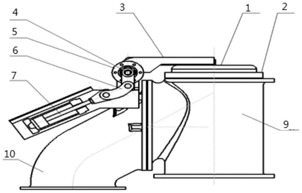
Ascending pipe cover for coke oven
Technical Field
The invention relates to the technical field of coke ovens, in particular to a riser cover for a coke oven.
Background
In the traditional technology, an ascending pipe and a bridge pipe are connected with a coke oven carbonization chamber and a gas collecting pipe, raw coke oven gas generated in the dry distillation process is led out, a cover of the ascending pipe is opened before pushing coke, the ascending pipe and the bridge pipe are cleaned in the period, the cover of the ascending pipe is closed after coal charging is finished, a water seal structure is adopted, and flowing water is used for keeping a certain water seal height so as to prevent the gas from escaping and polluting the atmosphere.
The operation of opening, closing of tedge lid is realized through manual pull rod or cylinder, and the epaxial installation balancing weight of tedge lid guarantees that pull rod power or cylinder power distribution are reasonable when the water seal lid is opened and is closed, and traditional tedge water seal lid is heavy relatively, and operating space is not big when opening back clearance tedge, bridge pipe, must supporting circulating water pipe system, and the cost is higher, if adopt the cylinder switching, still need increase limit switch control, and the structure is numerous and diverse, and the maintenance is difficult.
Disclosure of Invention
The ascending pipe cover for the coke oven is opened to leave enough ascending pipe and bridge pipe cleaning space, and the opening and closing operation is flexible, simple and reliable.
In order to achieve the purpose, the invention adopts the following technical scheme:
a kind of coke oven uses the riser cap, including riser cap, flange seat, pressure bar, axle, bearing bracket, tie rod, driving cylinder seat, the said flange seat is installed on the upper portion of the tee pipe, one end of the flange seat processes the seal gas inlet and seal gas channel, the said riser cap cooperates with flange seat to mount and compress tightly on the flange seat, the riser cap and flange seal gas channel correspond to the position to process and set up the annular seal gas channel, the said pressure bar is installed on riser cap of one side of bridge pipe, one end of the pressure bar is fixedly mounted in the middle position of the axle, the said axle is installed in bearing bracket, one end of the axle assembles the tie rod, the lower part of the tie rod installs the driving cylinder, the driving cylinder is fixedly mounted on driving cylinder seat, the said bearing bracket is installed on the bridge pipe, the said driving cylinder seat is installed on the bridge pipe.
The drive cylinder drive medium may be a gas or a liquid.
The ascending pipe cover and the flange seat can adopt cast iron or cast steel structures.
The application method of the ascending pipe cover for the coke oven comprises the following steps:
s1, a flange seat is arranged on a three-way pipe, a riser cover and the flange seat are arranged on the flange seat in a matching mode, and a sealing gas channel processed by the flange seat is communicated with an annular sealing gas channel processed by the riser cover.
S2, according to the positions of the ascending pipe cover and the shaft, a pressure rod is installed on the ascending pipe cover, the shaft is installed at the other end of the pressure rod, bearing seats are installed at two ends of the shaft, and the bearing seats are installed on the bridge pipe.
And S3, a connecting rod is arranged at the tail part of one end of the shaft, a driving cylinder is arranged at the lower part of the connecting rod and fixed on a driving cylinder seat, and the driving cylinder seat is arranged on the bridge pipe.
S4, when the ascending pipe cover is closed, the driving cylinder is installed on the bridge pipe through the driving cylinder seat, the driving cylinder rod drives the connecting rod and the shaft to rotate when retracting, the shaft and the pressing rod are in key connection, the pressing rod presses the ascending pipe cover, and the driving cylinder has the residual stroke at the moment and keeps the pressure of the driving cylinder.
S5, the ascending pipe cover is tightly pressed on the flange seat, sealing gas is introduced into a sealing gas inlet, the sealing gas enters an annular sealing gas channel between the ascending pipe cover and the flange seat, certain pressure is kept, gas inside the ascending pipe and external atmosphere can be effectively blocked, an annular gas sealing structure is formed, and the sealing requirement of the ascending pipe cover is met.
S6, when the ascending pipe cover needs to be opened, the driving cylinder rod extends outwards to drive the connecting rod and the shaft to rotate, the pressing rod is loosened to drive the ascending pipe cover to rotate and open, the driving cylinder is the limit position for opening the ascending pipe cover when all the driving cylinder extends out, and the opening angle of the ascending pipe cover is larger than 90 degrees.
When the ascending pipe cover is closed, the driving cylinder is required to have residual stroke and maintain pressure, and when the ascending pipe cover is completely opened, the driving cylinder has no residual stroke.
The tail end of the flange seat sealing gas channel is connected with an annular sealing gas channel in the ascending pipe cover.
Compared with the prior art, the invention has the beneficial effects that:
1) the ascending pipe cover with the air sealing structure is small in size, light in weight, simple in structure, easy to maintain, large in operation space when the ascending pipe and the bridge pipe are cleaned after being opened, and convenient for operators to clean.
2) The driving cylinder drives, the pressing force is large when the ascending pipe cover is closed, and the sealing effect is good; the water seal-free structure does not need to design a circulating water pipeline system, and the air seal structure is more reliable in sealing.
3) The opening and closing operation is simple, a limit switch is not required to be added, the structure is simplified, and faults are not easy to occur.
4) The ascending pipe cover and the flange seat are made of castings, so that the ascending pipe cover and the flange seat are effectively prevented from being heated and deformed, and the production and maintenance cost is reduced.
Drawings
FIG. 1 is a schematic view showing the structure of a riser cover for a coke oven according to the present invention.
FIG. 2 is a top view of a riser cover for a coke oven according to the present invention.
FIG. 3 is a gas seal structure view of a riser cover for a coke oven according to the present invention.
In the figure: 1. ascending pipe cover 2, flange seat 3, pressure rod 4, shaft 5, bearing seat 6 and connecting rod
7. Driving cylinder 8, driving cylinder seat 9, three-way pipe 10, bridge pipe 11 and sealing gas inlet
12. Sealing gas channel 13. annular sealing gas channel
Detailed Description
The following further describes embodiments of the present invention with reference to the accompanying drawings:
as shown in figure 1, the ascending pipe cover for the coke oven of the invention comprises an ascending pipe cover 1, a flange seat 2, a pressure rod 3, a shaft 4, a bearing seat 5, a connecting rod 6, a driving cylinder 7 and a driving cylinder seat 8, wherein the flange seat 2 is arranged at the upper part of a three-way pipe 9, one end of the flange seat 2 is provided with a sealing gas inlet 11 and a sealing gas channel 12, the ascending pipe cover 1 is arranged on the flange seat 2 in a manner of matching with the flange seat 2 in a pressing way, an annular sealing gas channel 13 is arranged at the position corresponding to the ascending pipe cover 1 and the flange sealing gas channel 12 in a processing way, when the ascending pipe cover 1 is closed, sealing gas is introduced into the annular sealing gas channel 13, the flowing sealing gas is used as a sealing part to ensure the sealing between the ascending pipe cover 1 and the flange seat 2, the pressure rod 3 is arranged on the ascending pipe cover 1 at one side of a bridge pipe, one end of the pressure rod 3 is fixedly arranged at the, the position of a shaft 4 is fixed by a bearing seat 5, a connecting rod 6 is assembled at one end of the shaft 4, a driving cylinder 7 is installed at the lower part of the connecting rod 6, the driving cylinder 7 is fixedly installed on a driving cylinder seat 8, when the lifting pipe cover is opened, a driving rod of the driving cylinder 7 acts and extends out to drive the connecting rod 5 to move, the shaft 4 and a pressure rod 3 rotate to open the lifting pipe cover 1, the bearing seat 5 is installed on a bridge pipe 10, and the driving cylinder seat 8 is installed on the bridge pipe 10.
The driving medium of the driving cylinder 7 can be gas or liquid.
The ascending pipe cover 1 and the flange seat 2 can adopt cast iron or cast steel structures, so that the thermal deformation is avoided, and the production and maintenance cost is reduced.
As shown in fig. 1, 2 and 3, the application method of the ascending pipe cover for the coke oven is as follows:
s1, a flange seat 2 is arranged on a three-way pipe 9, a riser cover 1 and the flange seat 2 are arranged on the flange seat 2 in a matching mode, and a sealing gas channel 12 processed by the flange seat 2 is communicated with an annular sealing gas channel 13 processed by the riser cover 1.
S2, according to the positions of the ascending pipe cover 1 and the shaft 4, a pressure rod 3 is installed on the ascending pipe cover 1, the shaft 4 is installed at the other end of the pressure rod 3, bearing seats 5 are installed at two ends of the shaft 4, and the bearing seats 5 are installed on a bridge pipe 10.
S3, a connecting rod 6 is installed at the tail of one end of the shaft 4, a driving cylinder 7 is installed at the lower portion of the connecting rod 6, the driving cylinder 7 is fixed on a driving cylinder seat 8, and the driving cylinder seat 8 is installed on a bridge pipe 10.
S4, when the ascending pipe cover 1 is closed, the driving cylinder 7 is installed on the bridge pipe 10 through the driving cylinder 8, the rod of the driving cylinder 8 retracts to drive the connecting rod 6 and the shaft 4 to rotate, the shaft 4 is in key connection with the pressing rod 3, the pressing rod 3 presses the ascending pipe cover 1 tightly, and at the moment, the driving cylinder 7 has the residual stroke and keeps the pressure of the driving cylinder.
S5, the ascending pipe cover 1 is tightly pressed on the flange seat 2, sealing gas is introduced at the sealing gas inlet 11, enters an annular sealing gas channel 13 between the ascending pipe cover 1 and the flange seat 2 and keeps a certain pressure, so that gas inside the ascending pipe and external atmosphere can be effectively blocked, an annular gas seal structure is formed, and the sealing requirement of the ascending pipe cover is met.
S6, when the ascending pipe cover 1 needs to be opened, the driving cylinder 7 extends outwards to drive the connecting rod 6 and the shaft 4 to rotate, the pressing rod 3 is loosened to drive the ascending pipe cover 1 to rotate and open, the driving cylinder 7 is the limit position of the ascending pipe cover 1 when extending out, and the opening angle of the ascending pipe cover 1 is larger than 90 degrees.
The driving cylinder 7 is required to have residual stroke and maintain pressure when the ascending pipe cover 1 is closed, and the driving cylinder 7 has no residual stroke when the ascending pipe cover 1 is completely opened.
As shown in fig. 3, the tail end of the sealing gas channel 12 of the flange base 2 is connected with an annular sealing gas channel 13 in the rising pipe cover 1, when the rising pipe cover 1 is closed, the sealing gas enters the sealing gas channel 12 through the sealing gas inlet 11, and enters the annular sealing gas channel 13 through the sealing gas channel 12, so as to complete the gas sealing function.
The working principle of the ascending pipe cover for the coke oven is as follows: utilize the sealed gas inlet 11 and the sealed gas channel 12 of processing on the flange seat 2 and the annular sealed air channel 13 UNICOM on the tedge lid 1, insert sealed gas, make and realize gas seal between tedge lid 1 and the flange seat 2, drive the cylinder rod through driving jar 7 and drive the motion of connecting rod 6, it rotates with depression bar 3 to drive axle 4 simultaneously, open and close tedge lid 1, need not limit switch and also can accomplish the 1 switching function of tedge lid, the action of tedge lid 1 is more nimble, sealed effect is better, the space is bigger, the cleaning work when being convenient for open.
The following examples are carried out on the premise of the technical scheme of the invention, and detailed embodiments and specific operation processes are given, but the scope of the invention is not limited to the following examples. The methods used in the following examples are conventional methods unless otherwise specified.
[ examples ] A method for producing a compound
As shown in fig. 1 and 2, the riser cover 1 is installed on a flange seat 2 according to design requirements, the flange seat 2 is installed on a three-way pipe 9, a bearing seat 5 is installed on a bridge pipe 10, and a driving cylinder seat 8 is installed on the bridge pipe 10.
As shown in fig. 3, the annular seal gas passage 13 of the riser cap 1 communicates with the seal gas passage 12 of the flange seat 2.
As shown in fig. 1 and 2, a pressure lever 3 is mounted on a riser cover 1, the tail end of the pressure lever 3 is assembled at the middle position of a shaft 4, one end of the shaft 4 is provided with a connecting rod 6, the lower part of the connecting rod 6 is provided with a driving cylinder 7, the shaft 4 is fixed through a bearing seat 5, and the driving cylinder 7 is fixed through a driving cylinder seat 8.
When the ascending pipe cover 1 is closed, the driving cylinder 7 is installed on the bridge pipe 10 through the driving cylinder 8, the driving cylinder 8 rod drives the connecting rod 6 and the shaft 4 to rotate when retracting, the shaft 4 is in key connection with the pressing rod 3, the pressing rod 3 presses the ascending pipe cover 1, the driving cylinder 7 has the residual stroke at the moment, the driving cylinder pressure is kept, the ascending pipe cover 1 is tightly pressed on the flange seat 2, the sealing gas is introduced at the sealing gas inlet 11, the sealing gas enters the annular sealing gas channel 13 between the ascending pipe cover 1 and the flange seat 2, and certain pressure is kept, the gas and the external atmosphere inside the ascending pipe can be effectively blocked, an annular gas sealing structure is formed, and the sealing requirement of the ascending pipe cover is met.
When the ascending pipe cover 1 needs to be opened, the driving cylinder 7 extends outwards to drive the connecting rod 6 and the shaft 4 to rotate, the pressing rod 3 is loosened to drive the ascending pipe cover 1 to rotate and open, the driving cylinder 7 is the limit position for opening the ascending pipe cover 1 when extending out, and the opening angle of the ascending pipe cover 1 is larger than 90 degrees.
When the device is used, the structure is simple, the occupied area is small, the operation space is large, the overhaul and cleaning work of operators are facilitated, the driving cylinder drives, the pressing force is large when the ascending pipe cover is closed, and the sealing effect is good; the water seal-free structure does not need to design a circulating water pipeline system, and the air seal structure is more reliable in sealing.