CN112770880B - Folding knife with frame lock guard - Google Patents
Folding knife with frame lock guard Download PDFInfo
- Publication number
- CN112770880B CN112770880B CN201980060293.3A CN201980060293A CN112770880B CN 112770880 B CN112770880 B CN 112770880B CN 201980060293 A CN201980060293 A CN 201980060293A CN 112770880 B CN112770880 B CN 112770880B
- Authority
- CN
- China
- Prior art keywords
- guard
- locking arm
- arm
- length
- longitudinal axis
- Prior art date
- Legal status (The legal status is an assumption and is not a legal conclusion. Google has not performed a legal analysis and makes no representation as to the accuracy of the status listed.)
- Active
Links
Images


Classifications
-
- B—PERFORMING OPERATIONS; TRANSPORTING
- B26—HAND CUTTING TOOLS; CUTTING; SEVERING
- B26B—HAND-HELD CUTTING TOOLS NOT OTHERWISE PROVIDED FOR
- B26B1/00—Hand knives with adjustable blade; Pocket knives
- B26B1/02—Hand knives with adjustable blade; Pocket knives with pivoted blade
- B26B1/04—Hand knives with adjustable blade; Pocket knives with pivoted blade lockable in adjusted position
-
- B—PERFORMING OPERATIONS; TRANSPORTING
- B26—HAND CUTTING TOOLS; CUTTING; SEVERING
- B26B—HAND-HELD CUTTING TOOLS NOT OTHERWISE PROVIDED FOR
- B26B1/00—Hand knives with adjustable blade; Pocket knives
- B26B1/02—Hand knives with adjustable blade; Pocket knives with pivoted blade
- B26B1/04—Hand knives with adjustable blade; Pocket knives with pivoted blade lockable in adjusted position
- B26B1/046—Hand knives with adjustable blade; Pocket knives with pivoted blade lockable in adjusted position with a locking member acting in axial direction parallel to the pivot axis of the blade
-
- B—PERFORMING OPERATIONS; TRANSPORTING
- B26—HAND CUTTING TOOLS; CUTTING; SEVERING
- B26B—HAND-HELD CUTTING TOOLS NOT OTHERWISE PROVIDED FOR
- B26B1/00—Hand knives with adjustable blade; Pocket knives
- B26B1/10—Handles
Landscapes
- Life Sciences & Earth Sciences (AREA)
- Forests & Forestry (AREA)
- Engineering & Computer Science (AREA)
- Mechanical Engineering (AREA)
- Knives (AREA)
Abstract
一种刀,其包括刀片和手柄组件。所述手柄组件可旋转地连接至所述刀片,并沿着纵向轴线延伸。所述手柄组件包括侧框架、手柄框架、锁定臂和保护件。所述手柄框架与所述侧框架间隔开并与所述侧框架限定腔体。所述锁定臂被连接至所述侧框架并能够在锁定位置和非锁定位置之间移动。所述锁定臂由臂长限定。所述保护件连接至所述侧框架,并且相对于所述纵向轴线从所述锁定臂向外定位。所述保护件沿着纵向轴线覆盖所述锁定臂的至少一部分,并由保护件长度限定。所述保护件长度与臂长的比值大于百分之七十五。
A knife includes a blade and a handle assembly. The handle assembly is rotatably connected to the blade and extends along a longitudinal axis. The handle assembly includes a side frame, a handle frame, a locking arm and a protector. The handle frame is spaced apart from the side frame and defines a cavity with the side frame. The locking arm is connected to the side frame and is movable between a locked position and an unlocked position. The locking arm is defined by the length of the arm. The guard is connected to the side frame and is positioned outwardly from the locking arm relative to the longitudinal axis. The guard covers at least a portion of the locking arm along the longitudinal axis and is defined by a guard length. The ratio of the length of the protective element to the length of the arm is greater than 75%.
Description
相关申请的交叉引用Cross References to Related Applications
本申请要求2018年9月18日提交的美国临时申请62/732,926号的权益和优先权,其内容通过引用整体合并至本文中。This application claims the benefit of and priority to U.S. Provisional Application No. 62/732,926, filed September 18, 2018, the contents of which are incorporated herein by reference in their entirety.
背景技术Background technique
本申请总体上涉及刀。更具体地,本申请涉及折叠刀,特别是框架锁定折叠刀。This application relates generally to knives. More particularly, the present application relates to folding knives, particularly frame lock folding knives.
框架锁定折叠刀通常包括连接至手柄的抑制锁定机构过度旋转的过度旋转抑制盘。但是,过度旋转抑制盘不会抑制使用者在打开或关闭刀时不经意地驱动锁定机构。这会导致使用者满意度降低。Frame lock folding knives typically include an overrotation inhibiting disc attached to the handle that inhibits overrotation of the locking mechanism. However, the over-rotation inhibiting disc does not inhibit the user from inadvertently actuating the locking mechanism when opening or closing the knife. This leads to a decrease in user satisfaction.
发明概述Summary of the invention
一个实施方案涉及一种刀,其包括刀片和可旋转地连接至刀片的手柄组件。手柄组件包括侧框架、连接至侧框架且能够在锁定位置和非锁定位置之间移动的锁定臂、以及保护件。锁定臂限定臂长。保护件连接至侧框架并且覆盖锁定臂的至少一部分。保护件在平行于臂长的方向上限定保护件长度,并且保护件长度与臂长的比值大于百分之七十五(75%)。One embodiment relates to a knife including a blade and a handle assembly rotatably connected to the blade. The handle assembly includes a side frame, a locking arm connected to the side frame and movable between a locked position and an unlocked position, and a guard. The locking arm defines the arm length. A protector is connected to the side frame and covers at least a portion of the locking arm. The protector defines a protector length in a direction parallel to the arm length, and the ratio of the protector length to the arm length is greater than seventy-five percent (75%).
另一个实施方案涉及一种刀,其包括刀片和可旋转地连接至刀片并限定纵向轴线的手柄组件。手柄组件包括侧框架、连接至侧框架且能够在锁定位置和非锁定位置之间移动的锁定臂、以及保护件。锁定臂在垂直于纵向轴线的方向上限定臂宽。保护件连接至侧框架并且覆盖锁定臂的至少一部分。保护件在垂直于纵向轴线的方向上限定保护件宽度,并且保护件宽度与臂宽的比值在沿着纵向轴线的任何给定位置处大于百分之三十(30%)。Another embodiment is directed to a knife including a blade and a handle assembly rotatably connected to the blade and defining a longitudinal axis. The handle assembly includes a side frame, a locking arm connected to the side frame and movable between a locked position and an unlocked position, and a guard. The locking arm defines an arm width in a direction perpendicular to the longitudinal axis. A protector is connected to the side frame and covers at least a portion of the locking arm. The guard defines a guard width in a direction perpendicular to the longitudinal axis, and the ratio of the guard width to the arm width is greater than thirty percent (30%) at any given location along the longitudinal axis.
另一个实施方案涉及一种刀,其包括刀片和可旋转地连接至刀片并限定纵向轴线的手柄组件。手柄组件包括手柄框架、连接至手柄框架的侧框架、以及通过活动铰链连接至侧框架并能够在锁定位置和非锁定位置之间移动的锁定臂。活动铰链将锁定臂朝向锁定位置偏压。锁定臂在垂直于纵向轴线的方向上限定臂宽并在平行于纵向轴线的方向上限定臂长。保护件连接至侧框架并且覆盖锁定臂的至少一部分。保护件在垂直于纵向轴线的方向上限定保护件宽度并在平行于纵向轴线的方向上限定保护件长度。保护件宽度与臂宽的比值在沿着纵向轴线的任何给定位置处大于百分之三十(30%),并且保护件长度与臂长的比值大于百分之七十五(75%)。Another embodiment is directed to a knife including a blade and a handle assembly rotatably connected to the blade and defining a longitudinal axis. The handle assembly includes a handle frame, a side frame connected to the handle frame, and a locking arm connected to the side frame by a living hinge and movable between a locked position and an unlocked position. A living hinge biases the locking arm toward the locked position. The locking arm defines an arm width in a direction perpendicular to the longitudinal axis and an arm length in a direction parallel to the longitudinal axis. A protector is connected to the side frame and covers at least a portion of the locking arm. The guard defines a guard width in a direction perpendicular to the longitudinal axis and a guard length in a direction parallel to the longitudinal axis. The ratio of the width of the guard to the width of the arm is greater than thirty percent (30%) at any given location along the longitudinal axis and the ratio of the length of the guard to the length of the arm is greater than seventy-five percent (75%) .
替代性的示例性实施方案涉及可能在权利要求中概括引述的其他特征和特征的组合。Alternative exemplary embodiments relate to other features and combinations of features that may be generally recited in the claims.
附图说明Description of drawings
从以下结合附图的详细描述中,本公开将变得更加充分地理解,其中,相同的附图标记指代相同的元件。The present disclosure will become more fully understood from the following detailed description taken in conjunction with the accompanying drawings, wherein like reference numerals refer to like elements.
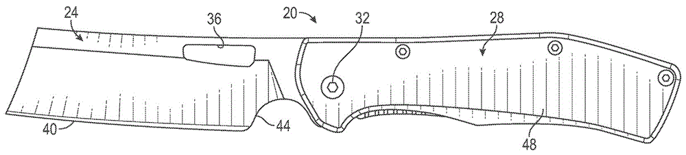
图1是根据示例性实施方案的处于打开或展开位置的刀的正视图。FIG. 1 is a front view of a knife in an open or deployed position, according to an exemplary embodiment.
图2是处于打开位置的图1的刀的后视图。Figure 2 is a rear view of the knife of Figure 1 in an open position.
图3是处于打开位置的图1的刀的细节透视图。Figure 3 is a detailed perspective view of the knife of Figure 1 in an open position.
图4是图1的刀的分解图。FIG. 4 is an exploded view of the knife of FIG. 1 .
图5是处于闭合或收起位置的图1的刀的正视图。Figure 5 is a front view of the knife of Figure 1 in a closed or stowed position.
图6是处于闭合位置的图1的刀的后视图。Figure 6 is a rear view of the knife of Figure 1 in a closed position.
图7是沿着图6的线7-7截取的图1的刀的截面图,其中刀片被移除。7 is a cross-sectional view of the knife of FIG. 1 taken along line 7-7 of FIG. 6 with the blade removed.
图8是图1的刀的框架锁定保护件的侧视图。8 is a side view of the frame lock guard of the knife of FIG. 1 .
图9是图8的框架锁定保护件的正视图。FIG. 9 is a front view of the frame lock protector of FIG. 8 .
详细描述A detailed description
在转向详细示出示例性实施方案的附图之前,应当理解,本申请不限于说明书中阐述的或在附图中示出的细节或方法。还应该理解,术语仅出于描述的目的,并且不应被视为限制。Before turning to the figures, which illustrate the exemplary embodiments in detail, it is to be understood that the application is not to be limited to the details or methodology set forth in the description or shown in the figures. It should also be understood that the terminology is for the purpose of description only and should not be regarded as limiting.
总体上参考附图,示出并描述了一种包括刀片的折叠刀,所述刀片可枢转地连接至手柄组件,并且能够在展开或“使用”位置和收起或“存储”位置之间移动。手柄组件包括侧框架、衬垫和手柄框架。锁定臂通过活动铰链连接至侧框架。锁定臂被构造为在锁定位置和非锁定位置之间移动,并且通过活动铰链被偏压向锁定位置。锁定保护件被连接至侧框架并且部分地覆盖锁定臂。当在使用位置和存储位置之间移动刀片时,锁定保护件被定位来抑制使用者驱动或按压锁定臂。Referring generally to the drawings, there is shown and described a folding knife including a blade pivotally connected to a handle assembly and capable of moving between a deployed or "use" position and a stowed or "storage" position move. The handle assembly includes side frames, pads and handle frame. The locking arms are connected to the side frames by living hinges. The locking arm is configured to move between a locked position and an unlocked position, and is biased toward the locked position by the living hinge. A locking guard is connected to the side frame and partially covers the locking arm. The locking guard is positioned to inhibit a user from actuating or depressing the locking arm when moving the blade between the use position and the storage position.
参考图1,刀20包括可旋转地连接至手柄组件28的刀片24。在一些实施例中,使用示出为枢轴销32的轴将刀片24固定至手柄组件28。刀片24被配置为在收起位置(如图5所示)和展开位置(如图1所示)之间绕枢转销32旋转。刀片24可以由硬质或其他刚性材料形成,并且适于切割、剁碎和/或切片物体。刀片24可以包括显示为打开孔36的打开部件,以及切割边缘40和指孔(finger choil)44。例如,打开孔36可以穿过刀片24的顶部形成,并且用作抓握部件来帮助使用者抓握和控制刀片24。例如,打开孔36的尺寸可以设置为容纳使用者的手指的一部分,用于在展开位置和存储位置之间驱动刀片24。打开孔36的形状和位置也可以变化从而适应不同的刀片形状和尺寸。尽管示出为负部件(negative feature)(即,凹口或孔),但是也可以将正形状(positive shape)和/或突出部并入或连接至刀片24以作为打开部件。例如,打开部件可以替代地是打开螺柱或圆柱形突出部(未示出)。Referring to FIG. 1 , the
手柄组件28包括手柄框架48。手柄框架48被成形为容纳刀片24的至少一部分,并且可以进一步成形为在使用和/或抓握刀20时为使用者提供人体工程学的舒适感。如图2所示,手柄组件28包括位于刀20上与手柄框架48相对的一侧上的侧框架52。侧框架52和手柄框架48彼此间隔开并且沿着刀20的长度彼此大致平行地延伸。侧框架52和手柄框架48一起限定腔体50,该腔体50被配置为当刀片24处于存储位置时接收刀片24的一部分(包括切割边缘40)。The
侧框架52包括通过活动铰链60连接至侧框架52的锁定臂56。通过阻止刀片24相对于手柄组件28的旋转,锁定臂56防止刀片24从展开位置到存储位置的不期望的旋转。锁定臂56能够在锁定位置(如图2所示)和非锁定位置(如图6所示)之间驱动。活动铰链60朝向锁定位置向内偏压锁定臂56。锁定臂56的向内偏压导致锁定臂56在存储位置接合刀片24,产生抵抗刀片24从手柄组件28离开的不期望的旋转的干扰和摩擦。拉动刀片24(例如,通过抓握打开孔36)可以克服锁定臂56的向内偏压。当刀片24旋转时,刀片24与锁定臂56之间的接触使锁定臂56朝向非锁定位置向外弯曲,这允许刀片24旋转。一旦刀片24旋转超出锁定臂56,则活动铰链60的自然偏压使锁定臂56返回到向内锁定位置,在该位置锁定臂56接合刀片24的柄脚42,并阻止刀片24相对于手柄组件28旋转。The
手柄组件28还可以包括安装部件,其允许使用者容易地使用并收起刀。例如,口袋夹64可以被紧固至侧框架52。口袋夹64的尺寸与使用者裤子的口袋接合,从而将刀20保持在适当的位置。使用固定在侧框架52上的螺丝钉或其他紧固件可以将口袋夹64固定至手柄组件28。侧框架52和手柄框架48可以由各种材料形成,包括金属材料(例如,铝)、聚合材料(例如,G10尼龙)、复合材料(例如,碳纤维)或这些材料的一些组合。The
除了锁定臂56和口袋夹64之外,侧框架52还限定出保护件凹口68。保护件凹口68可以延伸至侧框架52中,并且可以具有其尺寸被设计来容纳框架锁定保护件72的大体上的凹形。在一些实施例中,保护件凹口68部分地但不完全地延伸穿过侧框架52。然后从侧框架52的最外表面74向内形成伸长的肩部70。在一些实施例中,伸长的肩部70的周长模拟框架锁定保护件72的一部分。In addition to the locking
框架锁定保护件72被定位于保护件凹口68内。框架锁定保护件72可以是大体上平坦的板状部件,其在锁定臂56的至少一部分上延伸来防止锁定臂56的偶然的接触和驱动。框架锁定保护件72可以被紧固或以其他方式连接至侧框架52。在一些实施例中,锁定保护件72包括抓握部件。例如,突出部或脊部76可以远离框架锁定保护件72的表面80延伸。例如,脊部76可以沿着框架锁定保护件72的长度的一部分延伸,并且可以由大体上恒定的半圆形横截面限定。在一些实施方案中,脊部76由曲率限定并与框架锁定保护件72的外周长的一部分同心地延伸。框架锁定保护件72的表面80可以与侧框架52的外表面基本齐平,从而脊部76向外延伸超出侧框架52来形成止动件或抓握件。容纳框架锁定保护件72的保护件凹口68可以形成与框架锁定保护件72的厚度相对应的深度,使得框架锁保护件72的表面80与侧框架52的外表面齐平。The
继续参考图2,沿着刀20的长度限定纵向轴线82并垂直于纵向轴线82限定宽度轴线83。刀20由一系列不同的长度关系限定,这使得框架锁定刀20能够有效且容易地在收起位置和展开位置之间转换,反之亦然。例如,臂和铰链长度84由锁定臂56和活动铰链60限定且平行于纵向轴线82测量。臂长88由锁定臂56限定且平行于纵向轴线82测量。保护件长度92由框架锁定保护件72限定且平行于纵向轴线82测量。因此,臂和铰链长度84、臂长88和保护件长度92沿着刀20的长度平行于纵向轴线82彼此平行地限定。With continued reference to FIG. 2 , a
可以选择臂和铰链长度84、臂长88和保护件长度92之间的关系,使得锁定臂56可以在刀片24上提供必要的偏压,而不会受到不希望的摩擦引起的可能会影响刀片24从收起位置转换到展开位置的力。例如,保护件长度92与臂和铰链长度84的比值可以小于100%,使得锁定臂56和活动铰链60的至少一部分保持向外暴露,超出框架锁定保护件72。这种设置允许锁定臂56和铰链60相对于框架锁定保护件72保持可移动,并提供使用区域,使得使用者可以有意地接触并驱动锁定臂56,从而使刀在展开和收起位置之间转换。在一些实施方案中,保护件长度92是臂和铰链长度84的约百分之六十六(66%),允许活动铰链60的一部分和锁定臂56的一部分向外延伸超出框架锁定保护件72的每一侧。在一些实施方案中,保护件长度92与臂和铰链长度84的比值在大约百分之五十(50%)至大约百分之八十(80%)之间。框架锁定保护件72可以被定位于活动铰链60的前方,使得整个活动铰链60相对于框架锁定保护件72暴露。The relationship between the arm and hinge
框架锁定保护件72被设计为覆盖锁定臂56的大部分,从而完全限制或避免了使用者的手与锁定臂56之间的偶然接触。锁定臂56可以横跨(straddle)框架锁定保护件72,使得锁定臂56的一部分从框架锁定保护件72的每一侧(例如,根据沿着纵向轴线82的相对位置确定的前侧和后侧)向外延伸。通过使锁定臂56的一部分不被框架锁定保护件72覆盖,使用者可以通过直接接触锁定臂56来有意地驱动锁定臂56。在一些实施例中,框架锁定保护件72朝向活动铰链60被定位,使得锁定臂56的远端保持易于被使用者的手指接近和移动。在一些实施例中,保护件长度92与臂长88的比值可以是大约百分之八十七(87%)。为了在产生对锁定臂56的必要的可及性的同时仍然限制不必要的驱动,保护件长度92与臂长88的比值应该在大约百分之七十五(75%)至大约百分之一百(100%)之间。The
框架锁定保护件72和锁定臂56的纵向尺寸和位置以及宽度和纬度关系(即相对于宽度轴线83)允许框架锁定保护件72防止或抑制与锁定臂56的偶然接触的同时仍然允许有意地驱动锁定臂56。一系列的尺寸关系可以再次确定框架锁定保护件72的有效性。例如,锁定臂宽度96由锁定臂56在平行于宽度轴线83的方向上限定。锁定臂宽度96沿着锁定臂长度88变化。在一些实施方案中,锁定臂宽度96在最大处接近活动铰链60。锁定臂宽度96在锁定臂56的远端处比在锁定臂56的近端处更小。由锁定臂56和框架锁定保护件72两者限定的保护件宽度100处于平行于宽度轴线83的方向。保护件宽度100由锁定臂56的顶侧86到框架锁定保护件72的底侧90之间的距离限定。保护件宽度100也沿着保护件长度92变化。像锁定臂56一样,保护件宽度100可以在最大处靠近活动铰链60,并且在最小处靠近锁定臂56的远端。The longitudinal dimensions and location and width and latitudinal relationship (ie, relative to width axis 83 ) of
在一些实施方案中,保护件宽度100与锁定臂宽度96的比值在沿着保护件长度92的任何给定位置处在大约百分之四十五(45%)至大约百分之七十(70%)之间,从而允许锁定臂56的一部分在框架锁定保护件72下方保持暴露。在一些实施方案中,保护件宽度100与锁定臂宽度96的比值在框架锁定保护件72远离刀片24(即靠近活动铰链60)的一端为约百分之七十(70%),并且在框架锁定保护件72靠近刀片24(即靠近锁定臂56的远端)的一端为约百分之四十五(45%)。在一些实施方案中,保护件宽度100与锁定臂宽度96的比值沿着保护件长度92是一致的(例如,〜50%)。在一些实施方案中,保护件宽度100与锁定臂宽度96的比值在大约百分之三十(30%)至大约百分之一百(100%)之间。In some embodiments, the ratio of
如图3所示,保护件凹口68的尺寸设置为使得框架锁定保护件72的表面80与侧框架52的外表面齐平。锁定臂56还可以包括形状为容纳框架锁定保护件72的一部分的臂凹口104。臂凹口104可以形成为与框架锁定保护件72的底侧90互补的形状,并且可以设置为当锁定臂56向外偏压到非锁定位置(位于图3所示的锁定位置向外)时形成围绕框架锁定保护件72的间隙配合。在一些实施例中,框架锁定保护件72与臂凹口104的底部之间的接合可以用作止动件来防止锁定臂56被向外过度驱动超出期望的非锁定位置。臂凹口104的深度可以约等于框架锁定保护件72的厚度,使得当锁定臂56移动到非锁定位置时,侧框架52的外表面、表面80和锁定臂的外表面大体上彼此齐平地延伸。As shown in FIG. 3 , the
图4示出了刀20的内部结构和紧固构造。在一些实施例中,衬垫108被紧固至手柄框架48。因为手柄框架48可以被形成的比侧框架52更薄,所以衬垫108可以被用于帮助使刀片24在手柄组件28内平衡和居中。衬垫108可以通过间隔件112与侧框架52间隔开,该间隔件112形成在存储构型中容纳并保护刀片24的腔体50。尽管图4示出了使用多个不同的可移除紧固件固定在一起的刀20的部件,但是可以使用各种其他连接机构和技术来制造刀20。在一些实施方案中,手柄组件28的一些或所有部分在不使用可移除紧固件的情况下被粘附、焊接、钎焊、熔合或以其他方式连接或联接。FIG. 4 shows the internal structure and fastening configuration of the
图5和图6示出了处于存储位置的刀20。刀片24朝向手柄组件28旋转,使得切割边缘40被容纳在腔体50内并且隐藏在手柄组件28内。位于腔体50内的刀片24的部分干涉锁定臂56,并防止锁定臂56到达腔体50内的锁定位置。相反,锁定臂56绕活动铰链60向外旋转,进入非锁定位置,其中锁定臂56的一端停留在刀片24上。锁定臂56之间的干涉抵抗但不阻止刀片24相对于手柄组件28旋转,使得使用者仍然可以将刀片24旋转至展开位置。为了展开刀片24,使用者可以用一只手抓握刀片24,并用另一只手抓握手柄组件28。打开孔36被暴露并处于使用者的拇指易于接合的位置,并形成可以拉动的抓握点,从而使刀片24从框架组件28向外开始旋转。框架锁定保护件72被定位为向使用者提供抓握位置,从而允许手柄组件28被牢固地抓握而不会按压在或撞击在锁定臂56上。按压或以其他方式迫使锁定臂56进入刀片24可以引起在刀片24和锁定臂56之间额外的摩擦和干涉,从而阻止朝向展开位置的旋转,这可能会使使用者感到沮丧。框架锁定保护件72形成阻碍使用者的手接触锁定臂56的阻挡物。换句话说,框架锁定保护件72抑制锁定臂56朝向锁定位置的意外驱动。Figures 5 and 6 show the
如图7所示和如上所述,框架锁定保护件72的脊部76从表面80向外突出。在锁定位置(以实线示出)和非锁定位置(以虚线示出)中,脊部76比锁定臂56离手柄组件28的中心线突出得更远。脊部升高的轮廓为使用者提供了参考点和抓握部分,所述使用者在展开刀20的刀片24之前不看手柄就可以知道他或她的手已正确地定位在框架锁定保护装置72上。图7还示出了当锁定臂56被设置在非锁定位置时框架锁定保护件72如何被容纳在锁定臂56的臂凹口104内。As shown in FIG. 7 and described above, the
图8和图9示出了框架锁定保护件72的其他细节。具体地,脊部76是从表面80突出的弓形突起。在一些实施方案中,抓握部件包括滚花纹理(knurled texture)、螺栓、锥状突出或不同形状的脊部。此外,框架锁定保护件72显示为紧固在侧框架52上的独立组件。在一些实施方案中,框架锁定保护件72可以根据需要形成为侧框架52的一部分或粘附至侧框架52。Additional details of the
框架锁定保护件72有利地抑制使用者无意地抓握或按压锁定臂56。例如,当使用者接合刀片24上的打开孔36时,如果使用者不经意地按压在锁定臂56上,则刀片24向使用位置(参见图1)的驱动被抑制并给使用者带来不理想的感觉。框架锁定保护件72抑制使用者不经意地按压锁定臂56,并且避免了在使用位置和存储位置之间的不顺利驱动的情况。The
如各种示例性实施方案中所示的设备、系统和方法的构造和设置仅是说明性的。尽管在本公开中仅详细描述了几个实施方案,但是许多修改是可能的(例如,各种元件的尺寸、维度、结构、形状和比例的变化、参数的值、安装设置、材料的使用、颜色、方向等)。例如,示出为整体形成的一些元件可以由多个零件或元件构成,元件的位置可以颠倒或以其他方式改变,并且离散元件的性质或数量或位置可以改变或变化。因此,所有这样的修改旨在被包括在本公开的范围内。在不脱离本公开的范围的情况下,可以在示例性实施方案的设计、操作条件和设置中进行其他替换、修改、改变和省略。The construction and arrangement of the devices, systems and methods as shown in the various exemplary embodiments is illustrative only. Although only a few embodiments have been described in detail in this disclosure, many modifications are possible (e.g., changes in size, dimension, structure, shape and proportions of various elements, values of parameters, mounting settings, use of materials, color, orientation, etc.). For example, some elements shown as integrally formed may be constructed of multiple parts or elements, the position of elements may be reversed or otherwise varied, and the nature or number or position of discrete elements may be altered or varied. Accordingly, all such modifications are intended to be included within the scope of this disclosure. Other substitutions, modifications, changes and omissions may be made in the design, operating conditions and arrangement of the exemplary embodiments without departing from the scope of the present disclosure.
如本文所使用的,术语“大约”、“约”、“基本上”和类似术语旨在具有广泛的含义,与本公开内容所属领域的普通技术人员的普通和公认用法相一致。审阅本公开的本领域技术人员应当理解,这些术语旨在允许描述和要求保护的某些特征,而不将这些特征的范围限制为所提供的精确数值范围或几何关系。因此,这些术语应解释为表明所描述和要求保护的主题的非实质性或无关紧要的修改或变更被认为是在所附权利要求书中所述的本发明的范围内。As used herein, the terms "about", "approximately", "substantially" and similar terms are intended to have a broad meaning consistent with common and accepted usage by those of ordinary skill in the art to which this disclosure pertains. It should be understood by those of skill in the art who review this disclosure that these terms are intended to allow certain features described and claimed without restricting the scope of these features to the precise numerical ranges or geometric relationships provided. Accordingly, these terms should be construed to indicate that insubstantial or inconsequential modifications or variations of the subject matter described and claimed are considered to be within the scope of the invention as described in the appended claims.
尽管给出的详细附图和具体实施例描述了露营用具套件的各种示例性实施方案,但仅用于说明的目的。应当理解,本发明的应用不限于在前面的描述中阐述或在附图中示出的构造细节和部件的设置。此外,在不脱离本发明的范围的情况下,可以对示例性实施方案的设计、操作条件和结构进行其他替换、修改、改变和省略。The detailed drawings and specific examples, while describing various exemplary embodiments of the camping kit, are given for purposes of illustration only. It should be understood that the application of the invention is not limited to the details of construction and the arrangement of parts set forth in the foregoing description or shown in the drawings. Furthermore, other substitutions, modifications, changes and omissions may be made in the design, operating conditions and structure of the exemplary embodiments without departing from the scope of the present invention.
Claims (18)
Applications Claiming Priority (3)
| Application Number | Priority Date | Filing Date | Title |
|---|---|---|---|
| US201862732926P | 2018-09-18 | 2018-09-18 | |
| US62/732,926 | 2018-09-18 | ||
| PCT/IB2019/057826 WO2020058851A1 (en) | 2018-09-18 | 2019-09-17 | Folding knife with frame lock guard |
Publications (2)
| Publication Number | Publication Date |
|---|---|
| CN112770880A CN112770880A (en) | 2021-05-07 |
| CN112770880B true CN112770880B (en) | 2023-04-25 |
Family
ID=68069832
Family Applications (1)
| Application Number | Title | Priority Date | Filing Date |
|---|---|---|---|
| CN201980060293.3A Active CN112770880B (en) | 2018-09-18 | 2019-09-17 | Folding knife with frame lock guard |
Country Status (4)
| Country | Link |
|---|---|
| US (2) | US11285625B2 (en) |
| EP (2) | EP4520490A3 (en) |
| CN (1) | CN112770880B (en) |
| WO (1) | WO2020058851A1 (en) |
Families Citing this family (7)
| Publication number | Priority date | Publication date | Assignee | Title |
|---|---|---|---|---|
| CN112770880B (en) * | 2018-09-18 | 2023-04-25 | 菲斯科尔思品牌有限公司 | Folding knife with frame lock guard |
| TWI764684B (en) * | 2021-04-22 | 2022-05-11 | 高志成 | Knives and their sockets for quick and safe removal and fixing of blades |
| USD1098870S1 (en) * | 2024-01-12 | 2025-10-21 | Ken Onion Hawaii, Llc | Folding knife |
| USD1098869S1 (en) * | 2024-01-12 | 2025-10-21 | Ken Onion Hawaii, Llc | Folding knife |
| USD1097769S1 (en) | 2024-02-05 | 2025-10-14 | Fiskars Brands, Inc. | Folding knife |
| USD1097770S1 (en) | 2024-02-07 | 2025-10-14 | Fiskars Brands, Inc. | Folding knife |
| USD1097771S1 (en) | 2024-02-07 | 2025-10-14 | Fiskars Brands, Inc. | Folding knife |
Citations (1)
| Publication number | Priority date | Publication date | Assignee | Title |
|---|---|---|---|---|
| CN106914926A (en) * | 2015-12-25 | 2017-07-04 | 广西锐可户外工具制造有限公司 | The locking safeties of jack knife |
Family Cites Families (40)
| Publication number | Priority date | Publication date | Assignee | Title |
|---|---|---|---|---|
| US5131149A (en) * | 1991-06-19 | 1992-07-21 | Lynn C. Thompson | Folding knife |
| US5400509A (en) * | 1994-04-06 | 1995-03-28 | Collins; Walter W. | Folding knife with hidden frame and method of assembly |
| US5596808A (en) * | 1995-06-28 | 1997-01-28 | Lake; Ronald W. | Safety for knife-blade lock |
| US5694692A (en) * | 1995-08-14 | 1997-12-09 | American Consumer Products, Inc. | Injection molded bolster scale assemblies for a knife |
| US5769094A (en) * | 1996-12-27 | 1998-06-23 | Jenkins, Jr.; R. B. | Folding knife with blade carrier |
| US6101723A (en) * | 1997-08-26 | 2000-08-15 | Spyderco, Inc. | Folding knife with eccentric pivot pin |
| US6101724A (en) * | 1997-12-06 | 2000-08-15 | Gb Ii Corporation | Pocketknife with exposed blade |
| JP2001259255A (en) | 2000-02-23 | 2001-09-25 | Spyderco Inc | Locking mechanism for folding knife |
| US6434831B2 (en) * | 2000-02-24 | 2002-08-20 | Chia Yi Ent. Co., Ltd. | Folding knife with safety for blade |
| US6289592B1 (en) * | 2000-02-28 | 2001-09-18 | Ernest R. Emerson | Folding knife closing system |
| US20020104220A1 (en) * | 2001-02-02 | 2002-08-08 | Marfione Anthony L. | Hidden trigger double action folding knives |
| US20040154170A1 (en) * | 2002-05-08 | 2004-08-12 | Kain Charles L. | Releasable double locking knife |
| US7346988B2 (en) * | 2002-09-11 | 2008-03-25 | Allway Tools, Inc. | Soft handle non-retractable utility knife with quick release latch and method for making same |
| US6834432B1 (en) * | 2003-07-28 | 2004-12-28 | Proceeding Corp. | Pocket knife with lock design |
| TWM271682U (en) * | 2005-01-21 | 2005-08-01 | Jr-Cheng Gau | Improved design of foldable knife |
| US7293360B2 (en) * | 2005-04-13 | 2007-11-13 | Mentor Group, Llc | Knife blade opening mechanism |
| US7437822B2 (en) * | 2005-05-18 | 2008-10-21 | Gbii Corporation | Locking mechanism for folding knife |
| US7305768B2 (en) * | 2005-08-18 | 2007-12-11 | Mentor Group, Llc | Locking mechanism for folding tool |
| US20070151110A1 (en) * | 2005-12-19 | 2007-07-05 | Chia-Ying Chen | Folding knife with improved blade retraction mechanism |
| AT504384B1 (en) * | 2006-10-16 | 2011-12-15 | Victorinox Ag | POCKET TOOL, ESPECIALLY POCKETKNIVES |
| US7774940B2 (en) * | 2008-01-03 | 2010-08-17 | Dragon Nails, Inc. | Folding knife with puzzle piece locking mechanism |
| US20100212163A1 (en) * | 2009-02-23 | 2010-08-26 | Ray International Enterprises Co., Ltd. | Leaf Spring Assisted Opener |
| US20100242287A1 (en) * | 2009-03-24 | 2010-09-30 | Eugene Gregg Jameson | Three-dimensional pocketknife puzzle |
| US20100325897A1 (en) * | 2009-06-24 | 2010-12-30 | Hui-Tung Chu | Lock mechanism and a folding knife with the same |
| US20110067246A1 (en) * | 2009-07-02 | 2011-03-24 | Michael Gregory Perez | Linear slide action mechanical folding knife opening mechanism |
| US20120144677A1 (en) * | 2010-12-08 | 2012-06-14 | Wu-Chieh Chang | Folding knife |
| TWM408471U (en) * | 2011-01-17 | 2011-08-01 | Yan-Fen Luo | Folding knife |
| US8499460B1 (en) * | 2011-04-29 | 2013-08-06 | Robert E. Pearman | Spring assisted knife having separate cam insert |
| US9346176B2 (en) * | 2012-04-09 | 2016-05-24 | Jane Collins | Spring-assisted folding knife |
| US8752298B2 (en) * | 2012-04-09 | 2014-06-17 | Michael C. Collins | Spring-assisted folding knife |
| US9364957B2 (en) * | 2012-06-06 | 2016-06-14 | Ronald W. Lake | Adjustment screw for folding knife safety devices |
| EP2895306B1 (en) * | 2012-09-09 | 2018-10-17 | Benchmade Knife Co., Inc. | Folding knife with dual operational modes |
| US20140259687A1 (en) * | 2013-03-14 | 2014-09-18 | Bear & Son Cutlery, Inc. | Knife with assisted opening mechanism |
| US20150082640A1 (en) * | 2013-09-23 | 2015-03-26 | Glen Forrest Huff | Locking Mechanism for a Folding Knife |
| US9579807B2 (en) * | 2014-08-21 | 2017-02-28 | Hui-Tung Chu | Foldable knife with multiple switching modes |
| US10654180B2 (en) * | 2016-05-23 | 2020-05-19 | Gb Ii Corporation | Easily disassembled folding knife |
| CN105904484B (en) * | 2016-07-01 | 2018-01-09 | 阳江拓必拓科技股份有限公司 | A kind of jack knife with bit-stopping structure |
| TWM535139U (en) * | 2016-07-19 | 2017-01-11 | 廖順義 | Tool that ensures the stability and safety of the body |
| USD813341S1 (en) * | 2016-11-03 | 2018-03-20 | Fiskars Brands, Inc. | Knife |
| CN112770880B (en) * | 2018-09-18 | 2023-04-25 | 菲斯科尔思品牌有限公司 | Folding knife with frame lock guard |
-
2019
- 2019-09-17 CN CN201980060293.3A patent/CN112770880B/en active Active
- 2019-09-17 US US16/573,124 patent/US11285625B2/en active Active
- 2019-09-17 WO PCT/IB2019/057826 patent/WO2020058851A1/en not_active Ceased
- 2019-09-17 EP EP25154206.4A patent/EP4520490A3/en active Pending
- 2019-09-17 EP EP19778667.6A patent/EP3852981B1/en active Active
-
2022
- 2022-03-25 US US17/704,584 patent/US11919178B2/en active Active
Patent Citations (1)
| Publication number | Priority date | Publication date | Assignee | Title |
|---|---|---|---|---|
| CN106914926A (en) * | 2015-12-25 | 2017-07-04 | 广西锐可户外工具制造有限公司 | The locking safeties of jack knife |
Also Published As
| Publication number | Publication date |
|---|---|
| US20200086510A1 (en) | 2020-03-19 |
| WO2020058851A1 (en) | 2020-03-26 |
| EP3852981B1 (en) | 2025-03-05 |
| US11919178B2 (en) | 2024-03-05 |
| EP3852981A1 (en) | 2021-07-28 |
| US11285625B2 (en) | 2022-03-29 |
| US20220212356A1 (en) | 2022-07-07 |
| CN112770880A (en) | 2021-05-07 |
| EP4520490A3 (en) | 2025-08-20 |
| EP4520490A2 (en) | 2025-03-12 |
Similar Documents
| Publication | Publication Date | Title |
|---|---|---|
| CN112770880A (en) | Folding knife with frame locking protection | |
| US7437822B2 (en) | Locking mechanism for folding knife | |
| AU2007201485B2 (en) | Hand tool having fixed and rotatable implements and an associated locking mechanism | |
| US4837932A (en) | Locking blade pocket-knife | |
| US7000323B1 (en) | Fixed-blade knife with pivotable side pieces | |
| US4040181A (en) | Locking blade knife | |
| US5819414A (en) | Double action folding knife | |
| US6698099B2 (en) | Convertible knife | |
| US9149940B2 (en) | Side blade lock and release mechanism for use with a knife | |
| US7581321B2 (en) | Folding knife | |
| US5689885A (en) | Knife with blade-mounted pivotal lockback latch | |
| US6101724A (en) | Pocketknife with exposed blade | |
| US20060026844A1 (en) | Foldable knife | |
| US11453133B2 (en) | Folding knife | |
| US7536788B2 (en) | Folding knife | |
| US10538002B2 (en) | Folding knife with replaceable blade and locking mechanism | |
| US20050028388A1 (en) | Pizza cutter | |
| CA2653896A1 (en) | Cutting tool | |
| US6253455B1 (en) | Hand saw having a handle including a pivoted protector for protecting a blade | |
| US20090119925A1 (en) | Folding Tool | |
| JP2001523503A (en) | Manicure shears | |
| US1113168A (en) | Combined nail-file and cuticle-knife. | |
| JP4347109B2 (en) | 鋏, 鋏 assembly method and 鋏 with case | |
| WO1999058302A1 (en) | Folding knife | |
| US20220016791A1 (en) | Folding knife with user selectable knife locking mechanism |
Legal Events
| Date | Code | Title | Description |
|---|---|---|---|
| PB01 | Publication | ||
| PB01 | Publication | ||
| SE01 | Entry into force of request for substantive examination | ||
| SE01 | Entry into force of request for substantive examination | ||
| GR01 | Patent grant | ||
| GR01 | Patent grant |