CN112781237A - Waste heat recycling device of power plant boiler - Google Patents

Waste heat recycling device of power plant boiler Download PDF

Info

Publication number
CN112781237A
CN112781237A CN202011607513.0A CN202011607513A CN112781237A CN 112781237 A CN112781237 A CN 112781237A CN 202011607513 A CN202011607513 A CN 202011607513A CN 112781237 A CN112781237 A CN 112781237A
Authority
CN
China
Prior art keywords
ferrule
cavity
heating chamber
waste heat
pipe
Prior art date
Legal status (The legal status is an assumption and is not a legal conclusion. Google has not performed a legal analysis and makes no representation as to the accuracy of the status listed.)
Granted
Application number
CN202011607513.0A
Other languages
Chinese (zh)
Other versions
CN112781237B (en
Inventor
王成东
周民
刘景海
张宝君
毕天盛
陆俊俊
Current Assignee (The listed assignees may be inaccurate. Google has not performed a legal analysis and makes no representation or warranty as to the accuracy of the list.)
Huaneng Jiangyin Gas Turbine Thermal Power Co ltd
Original Assignee
Huaneng Jiangyin Gas Turbine Thermal Power Co ltd
Priority date (The priority date is an assumption and is not a legal conclusion. Google has not performed a legal analysis and makes no representation as to the accuracy of the date listed.)
Filing date
Publication date
Application filed by Huaneng Jiangyin Gas Turbine Thermal Power Co ltd filed Critical Huaneng Jiangyin Gas Turbine Thermal Power Co ltd
Priority to CN202011607513.0A priority Critical patent/CN112781237B/en
Publication of CN112781237A publication Critical patent/CN112781237A/en
Application granted granted Critical
Publication of CN112781237B publication Critical patent/CN112781237B/en
Active legal-status Critical Current
Anticipated expiration legal-status Critical

Links

Images

Classifications

    • FMECHANICAL ENGINEERING; LIGHTING; HEATING; WEAPONS; BLASTING
    • F24HEATING; RANGES; VENTILATING
    • F24HFLUID HEATERS, e.g. WATER OR AIR HEATERS, HAVING HEAT-GENERATING MEANS, e.g. HEAT PUMPS, IN GENERAL
    • F24H6/00Combined water and air heaters
    • FMECHANICAL ENGINEERING; LIGHTING; HEATING; WEAPONS; BLASTING
    • F24HEATING; RANGES; VENTILATING
    • F24HFLUID HEATERS, e.g. WATER OR AIR HEATERS, HAVING HEAT-GENERATING MEANS, e.g. HEAT PUMPS, IN GENERAL
    • F24H9/00Details
    • F24H9/02Casings; Cover lids; Ornamental panels

Landscapes

  • Engineering & Computer Science (AREA)
  • Physics & Mathematics (AREA)
  • Thermal Sciences (AREA)
  • Chemical & Material Sciences (AREA)
  • Combustion & Propulsion (AREA)
  • Mechanical Engineering (AREA)
  • General Engineering & Computer Science (AREA)
  • Heat-Pump Type And Storage Water Heaters (AREA)

Abstract

本发明公开了一种发电厂锅炉的余热循环利用装置,包括卡套,该卡套呈半圆形,所述卡套的底部开设有缺口,所述卡套呈中空状,该卡套的内腔被一隔板分隔成左右两个腔体,其中左侧腔体为气体加热腔,右侧腔体为液体加热腔;所述气体加热腔内沿竖直方向均匀设置有多个导热片,所述导热片的两端分别朝向卡套的前后两端延伸设置,气体加热腔和液体加热腔两者内部分别设置有多个用于加热气体的导热片及用于加热液体的匀热板,使用过程中可直接将卡套卡入在锅炉的外壁,利用锅炉外壁的余热将气体加热腔和液体加热腔通入的空气和液体进行加热,通过利用同一装置将余热转变为两种利用方式,减少了浪费,并提高了其使用的便捷性。

Figure 202011607513

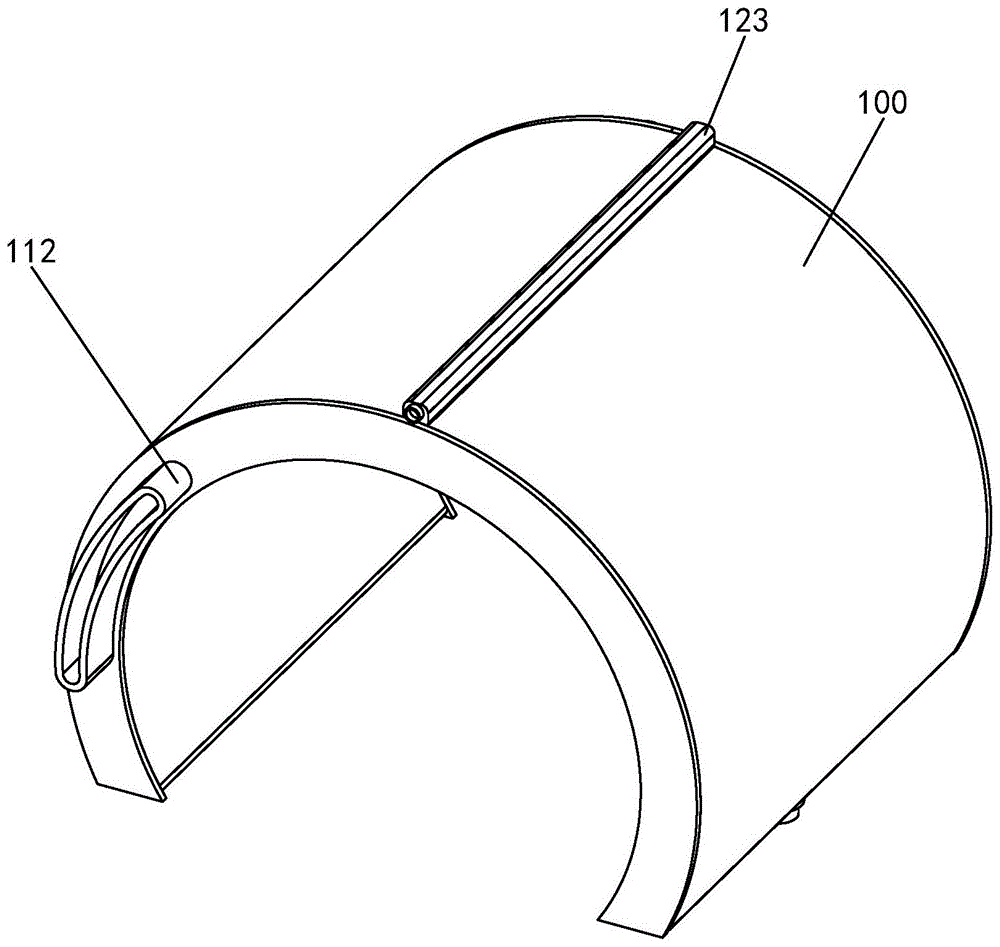
The invention discloses a waste heat recycling device for a boiler of a power plant, which comprises a ferrule, the ferrule is semi-circular, the bottom of the ferrule is provided with a notch, the ferrule is hollow, and the inner portion of the ferrule is hollow. The cavity is divided into left and right cavities by a partition, wherein the left cavity is a gas heating cavity, and the right cavity is a liquid heating cavity; a plurality of heat conducting sheets are evenly arranged in the vertical direction in the gas heating cavity, The two ends of the heat-conducting sheet extend toward the front and rear ends of the ferrule, respectively, and a plurality of heat-conducting sheets for heating gas and heat-dissipating plates for heating liquid are respectively arranged in the gas heating chamber and the liquid heating chamber. During use, the ferrule can be directly clamped to the outer wall of the boiler, and the air and liquid introduced into the gas heating chamber and the liquid heating chamber can be heated by the waste heat of the outer wall of the boiler, and the waste heat can be converted into two utilization methods by using the same device. Waste is reduced and ease of use is improved.

Figure 202011607513

Description

Waste heat recycling device of power plant boiler
Technical Field
The invention relates to the field of boilers, in particular to a waste heat recycling device of a power plant boiler.
Background
A power plant boiler, also called a "power plant boiler", refers to a medium or large boiler in a power plant that provides steam to a steam turbine in a specified amount and quality. One of the main thermal equipment of a thermal power plant. It is usually matched with a turbo-generator set with a certain capacity, mainly used for generating electricity, but also can be used for supplying heat to the outside in some special occasions. Generally, the evaporation capacity is large, steam parameters (steam temperature and steam pressure) are high, a whole set of auxiliary equipment is needed, chamber combustion chambers are needed to be configured, a forced ventilation mode is adopted, various fuels (coal powder, crude oil or heavy oil, blast furnace gas or coke oven gas) can be combusted, the structure is complex, the efficiency is high, most of the fuels can reach about 85-93%, and the requirements on the operation management level, the mechanization degree and the automatic control technology are quite high.
The heat generated by the outer wall of the existing power plant boiler is directly dissipated to the external environment during the use process, so that certain waste is caused during the long-term operation process, and the waste heat generated by the existing power plant boiler needs to be utilized.
Therefore, how to solve the defects of the prior art is a subject of the present invention.
Disclosure of Invention
In order to solve the problems, the invention discloses a waste heat recycling device of a power plant boiler.
In order to achieve the above purpose, the invention provides the following technical scheme: the waste heat recycling device of the power plant boiler comprises a cutting sleeve, wherein the cutting sleeve is semicircular, a notch is formed in the bottom of the cutting sleeve, the cutting sleeve is hollow, an inner cavity of the cutting sleeve is divided into a left cavity and a right cavity by a partition plate, the left cavity is a gas heating cavity, and the right cavity is a liquid heating cavity;
the gas heating cavity is internally and uniformly provided with a plurality of heat conducting fins along the vertical direction, two ends of each heat conducting fin extend towards the front end and the rear end of the corresponding clamping sleeve, the front end of each clamping sleeve is connected with an exhaust pipe corresponding to the gas heating cavity, the exhaust pipes are communicated with the gas heating cavity, the rear end of the gas heating cavity is provided with an opening, the opening is in a bent arc shape, a plurality of fans are installed on the clamping sleeves corresponding to the openings, the plurality of fans are arranged in an arc shape consistent with the openings, and the air outlet ends of the fans are arranged towards the gas heating cavity;
a plurality of heat distributing plates are arranged in the liquid heating cavity along the front-back direction and extend along the bending direction of the liquid heating cavity; form a aqua storage tank between two adjacent even hot plates, the top of cutting ferrule corresponds liquid heating chamber is connected with an even water pipe, the inner chamber of even water pipe with liquid heating chamber is linked together, the bottom of even water pipe corresponds each the aqua storage tank has been seted up respectively rather than matched with delivery port, the bottom of cutting ferrule corresponds liquid heating chamber is connected with a drain valve.
Furthermore, a gap is reserved between the bottom of the uniform heating plate and the bottom wall of the inner cavity of the liquid heating cavity, and the drain valve is communicated with the gap.
Further, the inner wall of the liquid heating cavity is coated with a non-stick coating, and the non-stick coating is a polytetrafluoroethylene coating.
Furthermore, the bottom surface laminating of cutting ferrule has a graphite alkene heat conduction membrane.
Furthermore, the outer wall of the clamping sleeve is further sleeved with a layer of heat insulation cloth, and the heat insulation cloth is aluminum silicate fiber cloth.
Further, the exhaust pipe and the drain valve are both communicated with a waste heat conveying pipe, the waste heat conveying pipe comprises an inner pipe and an outer pipe which are sleeved together, the inner pipe is inserted into an inner cavity of the outer pipe, the drain valve is communicated with the inner pipe, and the exhaust pipe is communicated with the outer pipe.
Compared with the prior art, the invention has the following advantages: the waste heat recycling device comprises a clamping sleeve, wherein the clamping sleeve is divided into a gas heating cavity and a liquid heating cavity, a plurality of heat conducting fins for heating gas and a heat homogenizing plate for heating liquid are respectively arranged in the gas heating cavity and the liquid heating cavity, the clamping sleeve can be directly clamped on the outer wall of a boiler in the using process, air and liquid introduced into the gas heating cavity and the liquid heating cavity are heated by using the waste heat of the outer wall of the boiler, and the waste heat is converted into two utilization modes by using the same device, so that the waste is reduced, and the use convenience is improved.
Drawings
FIG. 1 is a perspective view of the present invention;
FIG. 2 is a rear view of FIG. 1;
fig. 3 is a schematic internal view of a liquid heating chamber;
fig. 4 is a front sectional view of fig. 1.
List of reference numerals: 100 cutting sleeves, 101 gas heating cavities, 102 liquid heating cavities, 103 graphene heat conducting films, 111 heat conducting sheets, 112 exhaust pipes, 113 fans, 121 heat homogenizing plates, 122 water storage tanks, 123 water homogenizing pipes and 124 drain valves.
Detailed Description
The present invention will be further illustrated with reference to the accompanying drawings and specific embodiments, which are to be understood as merely illustrative of the invention and not as limiting the scope of the invention. It should be noted that the terms "front," "back," "left," "right," "upper" and "lower" used in the following description refer to directions in the drawings, and the terms "inner" and "outer" refer to directions toward and away from, respectively, the geometric center of a particular component.
Example (b): referring to fig. 1-4, a waste heat recycling device for a power plant boiler comprises a cutting sleeve 100, wherein the cutting sleeve 100 is semicircular, a gap is formed in the bottom of the cutting sleeve 100, the cutting sleeve 100 is hollow, an inner cavity of the cutting sleeve 100 is divided into a left cavity and a right cavity by a partition plate, wherein the left cavity is a gas heating cavity 101, and the right cavity is a liquid heating cavity 102; the clamping sleeve 100 is used for being clamped on the outer wall of the boiler; the whole cutting sleeve 100 is made of copper material;
a plurality of heat-conducting fins 111 are uniformly arranged in the gas heating cavity 101 along the vertical direction, two ends of each heat-conducting fin 111 extend towards the front end and the rear end of the clamping sleeve 100 respectively, the front end of the clamping sleeve 100 is connected with an exhaust pipe 112 corresponding to the gas heating cavity 101, the exhaust pipe 112 is communicated with the gas heating cavity 101, the rear end of the gas heating cavity 101 is open, the open is in a curved arc shape, a plurality of fans 113 are arranged on the clamping sleeve 100 corresponding to the open, the plurality of fans 113 are arranged in an arc shape consistent with the open, and the air outlet ends of the fans 113 are arranged towards the gas heating cavity 101;
the heat conducting fins 111 are made of copper sheets, waste heat of the boiler is transferred to the heat conducting fins 111 in a working state, external air is blown into the gas heating cavity 101 by the fan 113, the external air is heated by the relatively long heat conducting fins 111 and then blown out by the exhaust pipe 112, and the generated hot air can be introduced into a factory building needing to be heated so as to improve the utilization rate of the hot air;
a plurality of heat distributing plates 121 are arranged in the liquid heating cavity 102 along the front-back direction, and the plurality of heat distributing plates 121 extend along the bending direction of the liquid heating cavity 102; a water storage tank 122 is formed between two adjacent heat-homogenizing plates 121, the top of the cutting ferrule 100 is connected with a water-homogenizing pipe 123 corresponding to the liquid heating cavity 102, the inner cavity of the water-homogenizing pipe 123 is communicated with the liquid heating cavity 102, the bottom of the water-homogenizing pipe 123 is respectively provided with a water outlet matched with the water storage tank 122 corresponding to each water storage tank 122, and the bottom of the cutting ferrule 100 is connected with a water drainage valve 124 corresponding to the liquid heating cavity 102;
the uniform heating plate 121 can also be made of copper sheets, the waste heat of the boiler is transferred to the uniform heating plate 121 in a working state, external cold water is led to the uniform heating plate 121 through the water uniform pipe 123 and is discharged through the water discharge valve 124 after being heated by the uniform heating plate;
in order to ensure that the heated water can be gathered at the bottom of the liquid heating cavity 102 and uniformly discharged, a gap is reserved between the bottom of the heat homogenizing plate 121 and the bottom wall of the inner cavity of the liquid heating cavity 102, and the water discharge valve 124 is communicated with the gap.
To reduce the adhesion of impurities in the water to the interior walls of the liquid heating chamber 102, the interior walls of the liquid heating chamber 102 are coated with a non-stick coating of polytetrafluoroethylene.
In order to improve the thermal conductivity of the card sleeve 100, a graphene thermal conductive film 103 is attached to the bottom surface of the card sleeve 100.
In order to reduce the heat loss of the outer wall of the cutting sleeve 100, a layer of heat insulation cloth is further sleeved on the outer wall of the cutting sleeve 100, and the heat insulation cloth is aluminum silicate fiber cloth.
Exhaust pipe 112 and drain valve 124 all communicate with a waste heat conveyer pipe, and this waste heat conveyer pipe is including the inner tube and the outer tube that the cover was established together, and the inner tube inserts the inner chamber at the outer tube, and drain valve 124 is linked together with the inner tube, and exhaust pipe 112 is linked together with the outer tube, and the waste heat conveyer pipe adopts double-barrelled design, and the inner tube transmits hot water, and the outer tube transmits hot air, can reduce thermal scattering and disappearing in the water transmission in the inner tube, keeps higher temperature relatively.
The technical means disclosed in the invention scheme are not limited to the technical means disclosed in the above embodiments, but also include the technical scheme formed by any combination of the above technical features.

Claims (6)

1.一种发电厂锅炉的余热循环利用装置,其特征在于:包括卡套(100),该卡套(100)呈半圆形,所述卡套(100)的底部开设有缺口,所述卡套(100)呈中空状,该卡套(100)的内腔被一隔板分隔成左右两个腔体,其中左侧腔体为气体加热腔(101),右侧腔体为液体加热腔(102);1. A waste heat recycling device for a boiler of a power plant, characterized in that it comprises a ferrule (100), the ferrule (100) is semicircular, and a gap is provided at the bottom of the ferrule (100). The ferrule (100) is hollow, and the inner cavity of the ferrule (100) is divided into left and right cavities by a partition, wherein the left cavity is a gas heating cavity (101), and the right cavity is a liquid heating cavity cavity(102); 所述气体加热腔(101)内沿竖直方向均匀设置有多个导热片(111),所述导热片(111)的两端分别朝向卡套(100)的前后两端延伸设置,所述卡套(100)的前端对应所述气体加热腔(101)连接有一排气管(112),所述排气管(112)与所述气体加热腔(101)相连通,所述气体加热腔(101)的后端为敞口,该敞口呈弯曲的弧形状,所述卡套(100)上对应所述敞口安装有多个风扇(113),多个所述风扇(113)呈与所述敞口一致的弧形状排列,所述风扇(113)的出风端朝向所述气体加热腔(101)设置;A plurality of thermally conductive sheets (111) are evenly arranged in the gas heating chamber (101) along the vertical direction, and both ends of the thermally conductive sheets (111) are respectively extended towards the front and rear ends of the ferrule (100). The front end of the ferrule (100) is connected with an exhaust pipe (112) corresponding to the gas heating chamber (101), and the exhaust pipe (112) is communicated with the gas heating chamber (101), and the gas heating chamber The rear end of (101) is an opening, and the opening is in the shape of a curved arc. A plurality of fans (113) are installed on the ferrule (100) corresponding to the opening, and the plurality of fans (113) are in the shape of a curved arc. Arranged in an arc shape consistent with the opening, the air outlet end of the fan (113) is disposed toward the gas heating chamber (101); 所述液体加热腔(102)内沿前后方向排列有多个匀热板(121),多个所述匀热板(121)沿液体加热腔(102)的弯曲方向延伸设置;相邻两个匀热板(121)之间形成一储水槽(122),所述卡套(100)的顶部对应所述液体加热腔(102)连接有一匀水管(123),所述匀水管(123)的内腔与所述液体加热腔(102)相连通,所述匀水管(123)的底部对应各所述储水槽(122)分别开设有与其相配合的出水口,所述卡套(100)的底部对应所述液体加热腔(102)连接有一排水阀(124)。A plurality of uniform heating plates (121) are arranged in the liquid heating chamber (102) along the front-rear direction, and the plurality of uniform heating plates (121) are extended along the bending direction of the liquid heating chamber (102); two adjacent ones A water storage tank (122) is formed between the uniform heating plates (121), and a water uniform pipe (123) is connected to the top of the ferrule (100) corresponding to the liquid heating chamber (102). The inner cavity is communicated with the liquid heating cavity (102), and the bottom of the water-distributing pipe (123) is respectively provided with a water outlet corresponding to each of the water storage tanks (122). A drain valve (124) is connected to the bottom corresponding to the liquid heating chamber (102). 2.根据权利要求1所述的一种发电厂锅炉的余热循环利用装置,其特征在于:所述匀热板(121)的底部与所述液体加热腔(102)的内腔底壁留有间隙,所述排水阀(124)与所述间隙相连通。2. A waste heat recycling device for a boiler in a power plant according to claim 1, characterized in that: the bottom of the uniform heat plate (121) and the bottom wall of the inner cavity of the liquid heating chamber (102) are left with A gap, the drain valve (124) communicates with the gap. 3.根据权利要求1所述的一种发电厂锅炉的余热循环利用装置,其特征在于:所述液体加热腔(102)的内壁涂覆有一层不粘涂层,所述不粘涂层为聚四氟乙烯涂层。3. A waste heat recycling device for a power plant boiler according to claim 1, characterized in that: the inner wall of the liquid heating chamber (102) is coated with a layer of non-stick coating, and the non-stick coating is Teflon coating. 4.根据权利要求1所述的一种发电厂锅炉的余热循环利用装置,其特征在于:所述卡套(100)的底面贴合有一石墨烯导热膜(103)。4. A waste heat recycling device for a boiler of a power plant according to claim 1, characterized in that: a graphene thermal conductive film (103) is attached to the bottom surface of the ferrule (100). 5.根据权利要求1所述的一种发电厂锅炉的余热循环利用装置,其特征在于:所述卡套(100)的外壁还套设有一层隔热布,所述隔热布为硅酸铝纤维布。5. A waste heat recycling device for a power plant boiler according to claim 1, characterized in that: the outer wall of the ferrule (100) is also covered with a layer of heat insulating cloth, and the heat insulating cloth is silicic acid Aluminum fiber cloth. 6.根据权利要求1所述的一种发电厂锅炉的余热循环利用装置,其特征在于:所述排气管(112)及排水阀(124)均连通有一余热输送管,该余热输送管包括套设在一起的内管及外管,所述内管插入在外管的内腔,所述排水阀(124)与所述内管相连通,所述排气管(112)与所述外管相连通。6 . The waste heat recycling device for a boiler of a power plant according to claim 1 , wherein the exhaust pipe ( 112 ) and the drain valve ( 124 ) are both connected with a waste heat conveying pipe, and the waste heat conveying pipe comprises: 6 . The inner pipe and the outer pipe are sleeved together, the inner pipe is inserted into the inner cavity of the outer pipe, the drain valve (124) is communicated with the inner pipe, and the exhaust pipe (112) is connected with the outer pipe connected.
CN202011607513.0A 2020-12-30 2020-12-30 Waste heat recycling device of power plant boiler Active CN112781237B (en)

Priority Applications (1)

Application Number Priority Date Filing Date Title
CN202011607513.0A CN112781237B (en) 2020-12-30 2020-12-30 Waste heat recycling device of power plant boiler

Applications Claiming Priority (1)

Application Number Priority Date Filing Date Title
CN202011607513.0A CN112781237B (en) 2020-12-30 2020-12-30 Waste heat recycling device of power plant boiler

Publications (2)

Publication Number Publication Date
CN112781237A true CN112781237A (en) 2021-05-11
CN112781237B CN112781237B (en) 2022-08-02

Family

ID=75753410

Family Applications (1)

Application Number Title Priority Date Filing Date
CN202011607513.0A Active CN112781237B (en) 2020-12-30 2020-12-30 Waste heat recycling device of power plant boiler

Country Status (1)

Country Link
CN (1) CN112781237B (en)

Citations (22)

* Cited by examiner, † Cited by third party
Publication number Priority date Publication date Assignee Title
CN2214600Y (en) * 1995-03-15 1995-12-06 何挺佳 High efficiency all function boiler
JP2007075807A (en) * 2005-09-13 2007-03-29 Nobuaki Debari Organic material recycling equipment and wastewater treatment equipment
CN2886416Y (en) * 2006-03-14 2007-04-04 张润春 Waste heat utilizing boiler
US20080155985A1 (en) * 1997-12-23 2008-07-03 Gaudencio Aquino Labrador Heat Energy Recapture And Recycle And Its New Applications
CN101476714A (en) * 2009-01-09 2009-07-08 北京世纪源博科技有限责任公司 Multi-heat supply exhaust-heat boiler
CN201508036U (en) * 2009-09-28 2010-06-16 李守泉 Direct-fired tubular split organic heat carrier boiler
KR20110028677A (en) * 2009-09-14 2011-03-22 이동하 Hot water heating system using exhaust waste heat from heated kitchen equipment
CN201803442U (en) * 2010-07-28 2011-04-20 四川美德乐燃具有限公司 Water jacket for cooker
CN102278765A (en) * 2011-08-01 2011-12-14 亓振迎 Boiler dedusting waste heat recycling device
CN202303917U (en) * 2011-10-20 2012-07-04 河南中控柜架有限公司 Heat recycling device for medium and small-sized boilers
CN202747592U (en) * 2012-07-31 2013-02-20 陈和龙 Efficient and energy-saving boiler
US20140174697A1 (en) * 2012-12-26 2014-06-26 Kil Hwan Cho White smoke reducing system and method of recovering waste heat and water using the same
JP2015087027A (en) * 2013-10-28 2015-05-07 友章 吉川 Boiler device and carbonization system
US20150368564A1 (en) * 2013-02-06 2015-12-24 Envirollea Inc. Mobile plant for thermally treating a contaminated or uncontaminated feed stream, processes thereof and uses of products thereof
CN205316673U (en) * 2016-01-26 2016-06-15 南京轩能电力科技有限公司 Flue gas degree of depth waste heat recovery system of direct contact formula and wall type combination within a definite time
CN206330113U (en) * 2016-12-27 2017-07-14 兰州奥润环保设备有限公司 A kind of device for utilizing waste of boiler
CN206669702U (en) * 2016-12-23 2017-11-24 国核电力规划设计研究院 Steam generator system
CN206787031U (en) * 2017-05-01 2017-12-22 宣城凯欧纺织有限公司 A kind of UTILIZATION OF VESIDUAL HEAT IN energy-saving steam boiler
CN206929760U (en) * 2017-07-20 2018-01-26 张华� A kind of Industrial Boiler flue gas waste heat recovery apparatus
CN107975815A (en) * 2017-12-08 2018-05-01 亿利洁能科技(颍上)有限公司 A kind of coal-burning boiler device for utilizing residual heat of waste gas
CN108954812A (en) * 2018-07-30 2018-12-07 苏州仓江行电子科技有限公司 A kind of energy-efficient distributed normal pressure heating boiler of new energy
CN210688719U (en) * 2019-06-06 2020-06-05 中国电力企业联合会电力建设技术经济咨询中心 Energy-saving reconstruction device for boiler

Patent Citations (22)

* Cited by examiner, † Cited by third party
Publication number Priority date Publication date Assignee Title
CN2214600Y (en) * 1995-03-15 1995-12-06 何挺佳 High efficiency all function boiler
US20080155985A1 (en) * 1997-12-23 2008-07-03 Gaudencio Aquino Labrador Heat Energy Recapture And Recycle And Its New Applications
JP2007075807A (en) * 2005-09-13 2007-03-29 Nobuaki Debari Organic material recycling equipment and wastewater treatment equipment
CN2886416Y (en) * 2006-03-14 2007-04-04 张润春 Waste heat utilizing boiler
CN101476714A (en) * 2009-01-09 2009-07-08 北京世纪源博科技有限责任公司 Multi-heat supply exhaust-heat boiler
KR20110028677A (en) * 2009-09-14 2011-03-22 이동하 Hot water heating system using exhaust waste heat from heated kitchen equipment
CN201508036U (en) * 2009-09-28 2010-06-16 李守泉 Direct-fired tubular split organic heat carrier boiler
CN201803442U (en) * 2010-07-28 2011-04-20 四川美德乐燃具有限公司 Water jacket for cooker
CN102278765A (en) * 2011-08-01 2011-12-14 亓振迎 Boiler dedusting waste heat recycling device
CN202303917U (en) * 2011-10-20 2012-07-04 河南中控柜架有限公司 Heat recycling device for medium and small-sized boilers
CN202747592U (en) * 2012-07-31 2013-02-20 陈和龙 Efficient and energy-saving boiler
US20140174697A1 (en) * 2012-12-26 2014-06-26 Kil Hwan Cho White smoke reducing system and method of recovering waste heat and water using the same
US20150368564A1 (en) * 2013-02-06 2015-12-24 Envirollea Inc. Mobile plant for thermally treating a contaminated or uncontaminated feed stream, processes thereof and uses of products thereof
JP2015087027A (en) * 2013-10-28 2015-05-07 友章 吉川 Boiler device and carbonization system
CN205316673U (en) * 2016-01-26 2016-06-15 南京轩能电力科技有限公司 Flue gas degree of depth waste heat recovery system of direct contact formula and wall type combination within a definite time
CN206669702U (en) * 2016-12-23 2017-11-24 国核电力规划设计研究院 Steam generator system
CN206330113U (en) * 2016-12-27 2017-07-14 兰州奥润环保设备有限公司 A kind of device for utilizing waste of boiler
CN206787031U (en) * 2017-05-01 2017-12-22 宣城凯欧纺织有限公司 A kind of UTILIZATION OF VESIDUAL HEAT IN energy-saving steam boiler
CN206929760U (en) * 2017-07-20 2018-01-26 张华� A kind of Industrial Boiler flue gas waste heat recovery apparatus
CN107975815A (en) * 2017-12-08 2018-05-01 亿利洁能科技(颍上)有限公司 A kind of coal-burning boiler device for utilizing residual heat of waste gas
CN108954812A (en) * 2018-07-30 2018-12-07 苏州仓江行电子科技有限公司 A kind of energy-efficient distributed normal pressure heating boiler of new energy
CN210688719U (en) * 2019-06-06 2020-06-05 中国电力企业联合会电力建设技术经济咨询中心 Energy-saving reconstruction device for boiler

Also Published As

Publication number Publication date
CN112781237B (en) 2022-08-02

Similar Documents

Publication Publication Date Title
CN211120690U (en) Energy-saving boiler waste heat power generation device
CN112113203A (en) Electric heat storage steam device
CN112344365A (en) Boiler combustion furnace flue gas environmental protection and energy saving recovery unit
CN110173711A (en) A kind of combustion heat exchanger
TWM649586U (en) steam boiler
CN205481748U (en) Electromagnetism energy storage heat source device
CN112781237A (en) Waste heat recycling device of power plant boiler
CN105486133A (en) Heat pipe flue gas waste heat recycling device and working medium
CN201277797Y (en) Flue gas hollow paddle drier
CN204625576U (en) A kind of Novel water cooling wall for coal gasifier
CN104075336B (en) A kind of energy recycle device
CN114927719A (en) A constant temperature control device for hydrogen fuel cells
CN209214427U (en) Gas-to-gas heat recovery device
CN211146553U (en) Intubation type air preheater
CN207815858U (en) An industrial electric oven
CN207528079U (en) A kind of air preheating system of tubular heater
CN203823789U (en) Fuel gas waste heat recovery device
CN104534860A (en) Efficient insulation box wall of impregnated paper drying box
CN222747823U (en) Heat exchange device near the burner smoke outlet
CN222617530U (en) Energy-saving daily-use ceramic kiln
CN219511337U (en) Multistage heat exchanger with temperature monitoring function
CN213984054U (en) Heat Exchangers and Gas Water Heaters
CN220039129U (en) Energy recovery device and graphitization furnace
CN104499340A (en) Thermal insulation wall unit of impregnated paper drying box
CN209849219U (en) Energy-concerving and environment-protective formula aluminium foil coating drying device

Legal Events

Date Code Title Description
PB01 Publication
PB01 Publication
SE01 Entry into force of request for substantive examination
GR01 Patent grant
GR01 Patent grant
EE01 Entry into force of recordation of patent licensing contract

Application publication date: 20210511

Assignee: Huaneng Nanjing gas turbine power generation Co.,Ltd.

Assignor: Huaneng Jiangyin gas turbine thermal power Co.,Ltd.

Contract record no.: X2024980023308

Denomination of invention: Waste heat recycling device for power plant boilers

Granted publication date: 20220802

License type: Common License

Record date: 20241108

Application publication date: 20210511

Assignee: Henan Yutai Electric Power Engineering Co.,Ltd.

Assignor: Huaneng Jiangyin gas turbine thermal power Co.,Ltd.

Contract record no.: X2024980023307

Denomination of invention: Waste heat recycling device for power plant boilers

Granted publication date: 20220802

License type: Common License

Record date: 20241108

EE01 Entry into force of recordation of patent licensing contract