CN112834112B - Force standard device and hydraulic bearing device - Google Patents
Force standard device and hydraulic bearing device Download PDFInfo
- Publication number
- CN112834112B CN112834112B CN202110001140.0A CN202110001140A CN112834112B CN 112834112 B CN112834112 B CN 112834112B CN 202110001140 A CN202110001140 A CN 202110001140A CN 112834112 B CN112834112 B CN 112834112B
- Authority
- CN
- China
- Prior art keywords
- diaphragm
- hydraulic
- hydraulic pressure
- cavity
- head
- Prior art date
- Legal status (The legal status is an assumption and is not a legal conclusion. Google has not performed a legal analysis and makes no representation as to the accuracy of the status listed.)
- Active
Links
- 239000007788 liquid Substances 0.000 claims abstract description 16
- 238000009434 installation Methods 0.000 claims description 12
- BJQHLKABXJIVAM-UHFFFAOYSA-N bis(2-ethylhexyl) phthalate Chemical compound CCCCC(CC)COC(=O)C1=CC=CC=C1C(=O)OCC(CC)CCCC BJQHLKABXJIVAM-UHFFFAOYSA-N 0.000 claims description 7
- 230000013011 mating Effects 0.000 claims 2
- 238000005259 measurement Methods 0.000 description 10
- 230000003068 static effect Effects 0.000 description 4
- 239000012528 membrane Substances 0.000 description 3
- 238000012546 transfer Methods 0.000 description 3
- 238000010586 diagram Methods 0.000 description 2
- 238000000034 method Methods 0.000 description 2
- 238000007789 sealing Methods 0.000 description 2
- 230000002730 additional effect Effects 0.000 description 1
- 230000009286 beneficial effect Effects 0.000 description 1
- 230000005540 biological transmission Effects 0.000 description 1
- 238000010276 construction Methods 0.000 description 1
- 230000005489 elastic deformation Effects 0.000 description 1
- 238000012986 modification Methods 0.000 description 1
- 230000004048 modification Effects 0.000 description 1
- 238000012545 processing Methods 0.000 description 1
- 229910001220 stainless steel Inorganic materials 0.000 description 1
- 239000010935 stainless steel Substances 0.000 description 1
- 238000006467 substitution reaction Methods 0.000 description 1
- 238000012795 verification Methods 0.000 description 1
Images


Classifications
-
- G—PHYSICS
- G01—MEASURING; TESTING
- G01L—MEASURING FORCE, STRESS, TORQUE, WORK, MECHANICAL POWER, MECHANICAL EFFICIENCY, OR FLUID PRESSURE
- G01L25/00—Testing or calibrating of apparatus for measuring force, torque, work, mechanical power, or mechanical efficiency
Landscapes
- Physics & Mathematics (AREA)
- General Physics & Mathematics (AREA)
- Force Measurement Appropriate To Specific Purposes (AREA)
Abstract
The invention relates to a force standard device and a hydraulic bearing device, wherein the force standard device comprises a hydraulic bearing device, the hydraulic bearing device comprises a standard device main body with a hydraulic cavity, a diaphragm is arranged at the cavity opening of the hydraulic cavity, the force standard device also comprises a pressure sensor for detecting the liquid pressure in the hydraulic cavity, an inner pressure head positioned in the hydraulic cavity is fixed on the diaphragm, one end of the inner pressure head close to the diaphragm is a centering matching end in contact fit with the diaphragm, and an annular contact line in contact fit with the inner cavity wall line of the hydraulic cavity is formed at the outer edge of the contact position of the centering matching end and the diaphragm. The invention solves the technical problem that the diaphragm is easy to deform and lose efficacy because the size of the pressure head cannot be consistent with that of the hydraulic cavity in the prior art.
Description
Technical Field
The invention relates to a force standard device and a hydraulic bearing device in the field of force value measurement.
Background
In the metrological verification field, need use the power etalon to carry out the calibration of power value to various instruments, the press to thousands of tons greatly, little to pressure sensor, say so as to the output pressure of press carry out the power etalon of calibration, it includes the pneumatic cylinder, the pneumatic cylinder includes that cylinder body and cylinder body seal removal complex piston, be provided with the hydraulic pressure sensor that is used for detecting liquid pressure in the cylinder body on the cylinder body, when carrying out the calibration to the output pressure of press, the pressure head of press is exerted pressure to the piston, liquid pressure in the cylinder body is surveyed to hydraulic pressure sensor, then the atress of piston is the output pressure of press according to the effective area of contact of piston and liquid, thereby calibrate the press. Problems with such prior art force etalons are: the calibration accuracy is affected by friction between the piston and the cylinder, and particularly during the process of pressing the piston by the press, the friction is static friction, and the instability of the static friction also causes the instability of the reading of the hydraulic sensor, and finally, the calibration accuracy is affected.
In order to solve the technical problem that the static friction force between the piston and the cylinder body can influence the measurement accuracy, chinese patent CN1087600097A discloses a force measuring sensor, which comprises a sensor main body, wherein a hydraulic cavity is arranged at the bottom of the sensor main body, a diaphragm for plugging a cavity opening of the hydraulic cavity is fixed at the bottom of the sensor main body, and a pressing block is arranged at the lower side of the diaphragm. The sensor main body is provided with a pressure sensor for measuring the liquid pressure inside the hydraulic cavity, when the sensor main body is used, an external force acts on the sensor main body, the pressure block applies pressure to the hydraulic cavity through the diaphragm, the pressure sensor measures the liquid pressure inside the hydraulic cavity, then the acting force applied to the diaphragm is calculated according to the effective pressure bearing area of the diaphragm and the liquid, the acting force is opposite to the external force in the same direction, so that an external force value is obtained, from the upper analysis, whether the diaphragm deforms or not is a main factor influencing the measurement precision, in order to reduce the deformation of the diaphragm, the outer contour edge of the cross section of the pressure block is required to be coincident with or close to the inner side of the outer contour edge of the cross section of the liquid cavity in the prior art, namely, the closer the outer contour edge of the cross section of the pressure block is to the outer contour edge of the transverse basal plane of the hydraulic cavity, the smaller the force value applied to the contact position of the diaphragm and the pressure block is, the less prone to extension deformation, but the structure is that the pressure block and the hydraulic cavity are positioned at two sides of the diaphragm and the pressure chamber, the pressure block and the hydraulic cavity are not prone to be centered and the cross section of the hydraulic cavity, so that the pressure sensor can not be perfectly matched, the cross section of the pressure sensor in the upper pressure chamber, the cross section of the pressure sensor can be measured, the cross section of the pressure sensor, and the cross section of the pressure sensor can be slightly matched, and the pressure sensor, and the cross section of the pressure sensor can be measured. The method reduces the requirement on installation precision, realizes that the acting force of the pressing block only acts on liquid, but the part of the membrane between the outer contour of the pressing block and the outer contour of the hydraulic cavity is easy to deform, not only can the measurement precision be influenced, but also when large force value measurement is carried out, the hydraulic force can press the membrane at the position to generate non-elastic deformation which cannot be recovered, so that the membrane is invalid and cannot be used.
Disclosure of Invention
The invention aims to provide a force standard device to solve the technical problem that a diaphragm is easy to deform and lose efficacy due to the fact that the size of a pressure head cannot be consistent with that of a hydraulic cavity in the prior art; it is also an object of the present invention to provide a hydraulic load bearing device for use in such a force standard.
In order to solve the technical problems, the technical scheme of the force standard device is as follows:
the utility model provides a power standard ware, includes that hydraulic pressure bears the device, and hydraulic pressure bears the device including the standard ware main part that has the hydraulic pressure chamber, and the accent department in hydraulic pressure chamber is provided with the diaphragm, and power standard ware still includes the pressure sensor who is used for detecting hydraulic pressure intracavity liquid pressure, is fixed with on the diaphragm to be located the interior pressure head in the hydraulic pressure chamber, interior pressure head closes on the one end of diaphragm be for with diaphragm contact complex centering cooperation end, the contact position outer fringe of centering cooperation end and diaphragm form with the annular contact line of the inner chamber wall line contact complex in hydraulic pressure chamber.
The hydraulic pressure chamber is a cylindrical hydraulic pressure chamber, the annular contact line is an annular contact line, the inner pressure head is of a truncated spherical table structure, the spherical diameter of the inner pressure head gradually increases from the direction close to the diaphragm, and the spherical center of the inner pressure head is located on the axis of the hydraulic pressure chamber.
An annular pressing plate is fixed on one side, away from the standard device main body, of the diaphragm, an outer pressing head connected with the inner pressing head through a connecting section is arranged in an inner hole of the annular pressing plate, a connecting section through hole for the connecting section to penetrate through is formed in the middle of the diaphragm, the size of the outer contour of the outer pressing head is smaller than that of the inner cavity of the annular pressing plate, the inner cavity of the annular pressing plate and the hydraulic cavity are coaxially arranged, and the projections of the outer contour of the hydraulic cavity and the outer contour of the inner cavity of the annular pressing plate in the axial direction are overlapped.
The hydraulic cavity is provided with an upper cavity opening and a lower cavity opening which are oppositely arranged, and the upper cavity opening and the lower cavity opening are both provided with the diaphragms.
The annular pressing plate and the outer edge of the diaphragm are fixed on the standard device main body through bolts, an installation space is arranged between the annular pressing plate and the outer pressing head, a force transferring block with one end in contact fit with the diaphragm is arranged in the installation space, one side of the diaphragm deviates from the annular pressing plate, a force measuring block with the other end in contact fit with the force transferring block is arranged on one side of the diaphragm, and a strain gauge is attached to the force measuring block.
The technical scheme of the hydraulic bearing device comprises the following steps:
the hydraulic bearing device comprises a standard device main body with a hydraulic cavity, wherein a diaphragm is arranged at the cavity opening of the hydraulic cavity, an inner pressure head positioned in the hydraulic cavity is fixed on the diaphragm, one end of the inner pressure head close to the diaphragm is a centering matching end in contact fit with the diaphragm, and an annular contact line in line contact fit with the inner cavity wall of the hydraulic cavity is formed at the outer edge of the contact position of the centering matching end and the diaphragm.
The hydraulic pressure chamber is a cylindrical hydraulic pressure chamber, the annular contact line is an annular contact line, the inner pressure head is of a truncated spherical table structure, the spherical diameter of the inner pressure head gradually increases from the direction close to the diaphragm, and the spherical center of the inner pressure head is located on the axis of the hydraulic pressure chamber.
An annular pressing plate is fixed on one side, away from the standard device main body, of the diaphragm, an outer pressing head connected with the inner pressing head through a connecting section is arranged in an inner hole of the annular pressing plate, a connecting section through hole for the connecting section to penetrate through is formed in the middle of the diaphragm, the size of the outer contour of the outer pressing head is smaller than that of the inner cavity of the annular pressing plate, the inner cavity of the annular pressing plate and the hydraulic cavity are coaxially arranged, and the projections of the outer contour of the hydraulic cavity and the outer contour of the inner cavity of the annular pressing plate in the axial direction are overlapped.
The hydraulic cavity is provided with an upper cavity opening and a lower cavity opening which are oppositely arranged, and the upper cavity opening and the lower cavity opening are both provided with the diaphragms.
Annular clamp plate, diaphragm outer fringe pass through the bolt fastening in the etalon main part, have installation space between annular clamp plate and the outer press head, are equipped with one end and diaphragm contact complex biography power piece in the installation space, annular clamp plate deviates from one side of diaphragm be provided with pass the other one end contact complex dynamometry piece of power piece, post the strainometer on the dynamometry piece.
The invention has the beneficial effects that: the inner pressure head is positioned in the hydraulic cavity, namely the inner pressure head and the hydraulic cavity are positioned on one side of the diaphragm, when in processing, the size of the annular contact line of the centering matching end can be completely consistent with the size of the inner cavity of the hydraulic cavity, when in installation, the centering matching end is only installed in the hydraulic cavity, and because the inner pressure head is positioned in the hydraulic cavity, the size of the annular contact line can be completely consistent with the size of the inner cavity of the hydraulic cavity without worrying about the problem of assembly precision, so that the diaphragm is only used for sealing and is not used for bearing force, the diaphragm can not have the problem of extension deformation caused by unbalanced stress in the prior art, the annular contact line is in line contact fit with the hydraulic cavity, the contact area can be ignored, the static friction force between the centering matching end and the hydraulic cavity is very small and can be basically ignored, and the measurement precision is ensured.
Drawings
FIG. 1 is a schematic diagram of the structure of embodiment 1 of the force standard of the present invention;
FIG. 2 is a schematic diagram of the construction of embodiment 2 of the force standard of the present invention;
fig. 3 is a schematic structural view of embodiment 3 of the force standard of the present invention.
Detailed Description
Example 1 of a force standard according to the invention is shown in figure 1: including hydraulic pressure bearing device and pressure sensor (not shown in the figure), hydraulic pressure bearing device includes that the upper end is equipped with the etalon main part 1 in hydraulic pressure chamber 11, the accent department in hydraulic pressure chamber is equipped with diaphragm 2, the upside of diaphragm 2 is equipped with annular clamp plate 3, annular clamp plate, wear to be equipped with on diaphragm and the etalon main part and realize the fixed fixing bolt 12 of its three, hydraulic pressure chamber 11 is cylindrical hydraulic pressure chamber, the diameter in hydraulic pressure chamber 11 is unanimous with the hole diameter of annular clamp plate 3, annular clamp plate arranges with the hydraulic pressure chamber coaxial line, it is preferred, the diaphragm is the stainless steel piece. The pressure sensor is connected with the hydraulic cavity through an oil passage to measure the pressure of liquid in the hydraulic cavity.
When the pressure measuring device is used, when force is required to be measured by a force measuring device such as a hydraulic press, the pressure head of the hydraulic press applies pressure to the external pressure head 5, and compared with the prior art, the invention has the main differences that: the maximum size of the inner pressure head 10, namely the annular contact line, can be consistent with the size of the inner cavity of the hydraulic cavity, so that the diaphragm is not stressed by the action force in the opposite direction of the hydraulic pressure when the outer pressure head and the inner pressure head are stressed by the downward action force, the diaphragm is not extruded and deformed, the accuracy of force measurement and the service life of a product are ensured, and the diaphragm only plays a role of sealing liquid and is not stressed; the inner pressure head of the truncated ball table structure not only ensures that the contact area of the inner pressure head and the inner cavity wall of the hydraulic cavity is smaller, but also ensures the structural strength of the maximum diameter position of the inner pressure head. In other embodiments of the invention, the inner pressure head can also be a trapezoid structure with a large upper part and a small lower part, and the outer edge of the upper end of the inner pressure head forms an annular contact line which is in line contact fit with the inner cavity wall of the hydraulic cavity; the ring in the annular contact line in this embodiment is referred to as being closed in the circumferential direction, and may be a square ring in other embodiments, or may be another ring such as an elliptical ring.
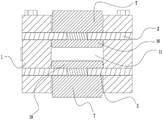
An embodiment 2 of a force standard is shown in fig. 2: embodiment 2 is different from embodiment 1 in that a hydraulic chamber 11 penetrates through a standard device main body in the up-down direction, the hydraulic chamber is provided with an upper chamber opening and a lower chamber opening which are oppositely arranged, and the upper chamber opening and the lower chamber opening are respectively provided with a diaphragm 2, an inner pressure head 10 and an outer pressure head 7.
An embodiment 3 of a force standard is shown in fig. 3, wherein: the difference between the embodiment 3 and the embodiment 1 is that the size of an inner hole of the annular pressing plate 3 is larger than the diameter of an inner cavity of the hydraulic cavity 11, an installation space is arranged between the annular pressing plate 3 and the outer pressing head 7, a force transfer block 15 with one end in contact fit with the diaphragm is arranged in the installation space, the force transfer block is of an annular structure, a force measurement block 13 in contact fit with the other end of the force transfer block is arranged on one side, away from the diaphragm, of the annular pressing plate 3, a strain gauge 14 is attached to the force measurement block, and the force measurement block 13, the annular pressing plate and the diaphragm are fixed on the standard device main body 1 through bolts 12. The additional effects of this embodiment are: when part of liquid leaks to the upper side of the annular contact wire through the contact position of the annular contact wire and the hydraulic cavity, the diaphragm at the position can deform upwards, the deformation force is transmitted to the force measuring block through the force transmission block, the force measuring block deforms, the strain gauge measures the force, and the force is compensated through the measuring force and the stress of the inner pressure head, so that the stress of the outer pressure head is accurately calculated.
Finally, it should be noted that: the above examples are only intended to illustrate the technical solution of the present invention, but not to limit it; although the present invention has been described in detail with reference to the foregoing embodiments, it will be understood by those of ordinary skill in the art that: the technical solutions described in the foregoing embodiments may still be modified, or some technical features may be equivalently replaced; and such modifications or substitutions do not depart from the spirit and scope of the corresponding technical solutions of the embodiments of the present invention.
Examples of hydraulic support devices are shown in fig. 1 to 3: the specific structure of the hydraulic bearing device is the same as the hydraulic bearing device described in the above embodiments of the force standard, and will not be described in detail here.
Claims (8)
1. The utility model provides a power standard ware, includes that hydraulic pressure bears the device, and hydraulic pressure bears the device including the standard ware main part that has the hydraulic pressure chamber, and the accent department in hydraulic pressure chamber is provided with the diaphragm, and power standard ware is still including the pressure sensor who is used for detecting hydraulic pressure intracavity liquid pressure, its characterized in that: be fixed with on the diaphragm be located the interior pressure head in the hydraulic pressure chamber, interior pressure head closes on the one end of diaphragm be with diaphragm contact complex centering cooperation end, the contact position outer fringe of centering cooperation end and diaphragm form with the inner chamber wall line contact complex annular contact line in hydraulic pressure chamber, the hydraulic pressure chamber is cylindrical hydraulic pressure chamber, annular contact line is ring form contact line, and interior pressure head is truncated spherical table structure, and the sphere diameter of interior pressure head is close to the diaphragm direction grow gradually from the orientation, and the sphere center of interior pressure head is in on the axis in hydraulic pressure chamber, and pressure sensor links to each other with the hydraulic pressure chamber through the oil duct in order to measure the pressure of hydraulic pressure intracavity liquid.
2. The force standard of claim 1, wherein: one side of the diaphragm, which deviates from the standard device main body, is fixedly provided with an annular pressing plate, an inner hole of the annular pressing plate is internally provided with an outer pressing head connected with the inner pressing head through a connecting section, the middle part of the diaphragm is provided with a connecting section through hole for the connecting section to pass through, the outer contour size of the outer pressing head is smaller than that of an inner cavity of the annular pressing plate, the inner cavity of the annular pressing plate and the hydraulic cavity are coaxially arranged, and the outer contour of the hydraulic cavity and the outer contour of the inner cavity of the annular pressing plate are overlapped in axial projection.
3. The force standard of claim 1, wherein: the hydraulic cavity is provided with an upper cavity opening and a lower cavity opening which are oppositely arranged, and the upper cavity opening and the lower cavity opening are both provided with the diaphragms.
4. The force standard of claim 3, wherein: annular clamp plate, diaphragm outer fringe pass through the bolt fastening in the etalon main part, have installation space between annular clamp plate and the outer press head, are equipped with one end and diaphragm contact complex biography power piece in the installation space, annular clamp plate deviates from one side of diaphragm be provided with pass the other one end contact complex dynamometry piece of power piece, post the strainometer on the dynamometry piece.
5. Hydraulic pressure bears device, including the etalon main part that has the hydraulic pressure chamber, the accent department in hydraulic pressure chamber is provided with diaphragm, its characterized in that: be fixed with on the diaphragm and be located interior pressure head in the hydraulic pressure intracavity, interior pressure head closes on the one end of diaphragm be with diaphragm contact complex centering mating end, the contact position outer fringe of centering mating end and diaphragm form with the inner chamber wall line contact complex ring-shaped contact line in hydraulic pressure chamber, the hydraulic pressure chamber is cylindrical hydraulic pressure chamber, ring-shaped contact line is ring-shaped contact line, and interior pressure head is truncated spherical table structure, and the sphere diameter of interior pressure head is close to the diaphragm direction grow gradually from the orientation, and the sphere center of interior pressure head is in on the axis in hydraulic pressure chamber, and pressure sensor passes through the oil duct and links to each other in order to measure the pressure of hydraulic pressure intracavity liquid with the hydraulic pressure chamber.
6. The hydraulic load bearing device of claim 5, wherein: an annular pressing plate is fixed on one side, away from the standard device main body, of the diaphragm, an outer pressing head connected with the inner pressing head through a connecting section is arranged in an inner hole of the annular pressing plate, a connecting section through hole for the connecting section to penetrate through is formed in the middle of the diaphragm, the size of the outer contour of the outer pressing head is smaller than that of the inner cavity of the annular pressing plate, the inner cavity of the annular pressing plate and the hydraulic cavity are coaxially arranged, and the projections of the outer contour of the hydraulic cavity and the outer contour of the inner cavity of the annular pressing plate in the axial direction are overlapped.
7. The hydraulic load bearing device of claim 5, wherein: the hydraulic cavity is provided with an upper cavity opening and a lower cavity opening which are oppositely arranged, and the upper cavity opening and the lower cavity opening are both provided with the diaphragms.
8. The hydraulic load bearing device of claim 7, wherein: the annular pressing plate and the outer edge of the diaphragm are fixed on the standard device main body through bolts, an installation space is arranged between the annular pressing plate and the outer pressing head, a force transferring block with one end in contact fit with the diaphragm is arranged in the installation space, one side of the diaphragm deviates from the annular pressing plate, a force measuring block with the other end in contact fit with the force transferring block is arranged on one side of the diaphragm, and a strain gauge is attached to the force measuring block.
Priority Applications (1)
| Application Number | Priority Date | Filing Date | Title |
|---|---|---|---|
| CN202110001140.0A CN112834112B (en) | 2021-01-04 | 2021-01-04 | Force standard device and hydraulic bearing device |
Applications Claiming Priority (1)
| Application Number | Priority Date | Filing Date | Title |
|---|---|---|---|
| CN202110001140.0A CN112834112B (en) | 2021-01-04 | 2021-01-04 | Force standard device and hydraulic bearing device |
Publications (2)
| Publication Number | Publication Date |
|---|---|
| CN112834112A CN112834112A (en) | 2021-05-25 |
| CN112834112B true CN112834112B (en) | 2023-01-06 |
Family
ID=75927242
Family Applications (1)
| Application Number | Title | Priority Date | Filing Date |
|---|---|---|---|
| CN202110001140.0A Active CN112834112B (en) | 2021-01-04 | 2021-01-04 | Force standard device and hydraulic bearing device |
Country Status (1)
| Country | Link |
|---|---|
| CN (1) | CN112834112B (en) |
Families Citing this family (1)
| Publication number | Priority date | Publication date | Assignee | Title |
|---|---|---|---|---|
| CN120721280B (en) * | 2025-07-30 | 2026-02-03 | 北京市石景山区检验检测中心 | Pressure metering device for mechanics experiments |
Citations (14)
| Publication number | Priority date | Publication date | Assignee | Title |
|---|---|---|---|---|
| US4798094A (en) * | 1988-01-11 | 1989-01-17 | The Unites States Of America As Represented By The Secretary Of The Army | Hydrostatic primary force standard |
| KR900010373A (en) * | 1988-12-30 | 1990-07-07 | 존 쉬아토차 | Differential Capacitive Detector with Overpressure Protection |
| JP2003056712A (en) * | 2001-08-14 | 2003-02-26 | Global Cooling Bv | Low friction follow-up seal for free piston stirling device |
| CN103245458A (en) * | 2013-04-07 | 2013-08-14 | 北京机械设备研究所 | Half-sine quasi-static calibration device of force sensor |
| CN103912566A (en) * | 2013-12-27 | 2014-07-09 | 镇江恒宇传动机械有限责任公司 | Spline assembly centring guiding structure and processing method thereof |
| CN204330476U (en) * | 2014-12-17 | 2015-05-13 | 天津工程机械研究院 | Fatigue tester friction pair |
| CN204627768U (en) * | 2015-05-15 | 2015-09-09 | 泉州特库克汽车零部件有限公司 | A kind of Novel engine cylinder sleeve |
| CN105136386A (en) * | 2015-09-24 | 2015-12-09 | 昆山市交通工程试验检测中心 | Force value test device |
| CN204988859U (en) * | 2015-05-06 | 2016-01-20 | 廊坊金润电气有限公司 | Dynamometer |
| CN108760097A (en) * | 2018-02-28 | 2018-11-06 | 南京元感微电子有限公司 | A kind of load cell |
| CN209244975U (en) * | 2018-12-24 | 2019-08-13 | 尚廷东 | The hydraulic loading device of included standard force source |
| CN110398315A (en) * | 2019-01-25 | 2019-11-01 | 尚廷东 | A kind of power standard and hydraulic bearing device |
| CN110887588A (en) * | 2019-12-13 | 2020-03-17 | 湃瑞电子科技(苏州)有限公司 | A thin film micro pressure sensor |
| CN214667419U (en) * | 2021-01-04 | 2021-11-09 | 郑州东辰科技有限公司 | Force standard device and hydraulic bearing device |
Family Cites Families (6)
| Publication number | Priority date | Publication date | Assignee | Title |
|---|---|---|---|---|
| NL7906279A (en) * | 1979-08-17 | 1981-02-19 | Goudsche Machinefabriek Bv | CALIBRATION UNIT FOR CALIBRATION OF A HYDRAULIC OR ELECTRICAL PRESSURE MEASUREMENT ELEMENT, IN PARTICULAR OF A PROBE. |
| US6435150B1 (en) * | 2000-07-25 | 2002-08-20 | Daimlerchrysler Corporation | Offset tappet assembly |
| US20110146417A1 (en) * | 2009-12-23 | 2011-06-23 | Sheeks Oliver P | Portable, hydraulic, direct force, readout apparatus |
| NL2010455C2 (en) * | 2013-03-14 | 2014-09-16 | Glind Metrology B V | Hydraulic pressure calibrator and calibration method. |
| CN108195503A (en) * | 2018-02-09 | 2018-06-22 | 扬州江天流量仪表有限公司 | Circular iris resistance-strain type pressure, differential pressure pickup |
| CN109374202A (en) * | 2018-11-12 | 2019-02-22 | 尚廷东 | A kind of fluid pressure type power calibrating installation |
-
2021
- 2021-01-04 CN CN202110001140.0A patent/CN112834112B/en active Active
Patent Citations (14)
| Publication number | Priority date | Publication date | Assignee | Title |
|---|---|---|---|---|
| US4798094A (en) * | 1988-01-11 | 1989-01-17 | The Unites States Of America As Represented By The Secretary Of The Army | Hydrostatic primary force standard |
| KR900010373A (en) * | 1988-12-30 | 1990-07-07 | 존 쉬아토차 | Differential Capacitive Detector with Overpressure Protection |
| JP2003056712A (en) * | 2001-08-14 | 2003-02-26 | Global Cooling Bv | Low friction follow-up seal for free piston stirling device |
| CN103245458A (en) * | 2013-04-07 | 2013-08-14 | 北京机械设备研究所 | Half-sine quasi-static calibration device of force sensor |
| CN103912566A (en) * | 2013-12-27 | 2014-07-09 | 镇江恒宇传动机械有限责任公司 | Spline assembly centring guiding structure and processing method thereof |
| CN204330476U (en) * | 2014-12-17 | 2015-05-13 | 天津工程机械研究院 | Fatigue tester friction pair |
| CN204988859U (en) * | 2015-05-06 | 2016-01-20 | 廊坊金润电气有限公司 | Dynamometer |
| CN204627768U (en) * | 2015-05-15 | 2015-09-09 | 泉州特库克汽车零部件有限公司 | A kind of Novel engine cylinder sleeve |
| CN105136386A (en) * | 2015-09-24 | 2015-12-09 | 昆山市交通工程试验检测中心 | Force value test device |
| CN108760097A (en) * | 2018-02-28 | 2018-11-06 | 南京元感微电子有限公司 | A kind of load cell |
| CN209244975U (en) * | 2018-12-24 | 2019-08-13 | 尚廷东 | The hydraulic loading device of included standard force source |
| CN110398315A (en) * | 2019-01-25 | 2019-11-01 | 尚廷东 | A kind of power standard and hydraulic bearing device |
| CN110887588A (en) * | 2019-12-13 | 2020-03-17 | 湃瑞电子科技(苏州)有限公司 | A thin film micro pressure sensor |
| CN214667419U (en) * | 2021-01-04 | 2021-11-09 | 郑州东辰科技有限公司 | Force standard device and hydraulic bearing device |
Non-Patent Citations (2)
| Title |
|---|
| The Dynamic Calibration Method of High-Pressure Transducer under High-Static Pressure;Zhang Yu 等;《2011 International Conference on Mechatronic Science, Electric Engineering and Computer (MEC)》;20110923;第1403-1406页 * |
| 叠加式力标准装置的力值传递规律研究及应用;薛金;《中国优秀博硕士学位论文全文数据库(硕士)工程科技Ⅱ辑》;20190715;C030-92 * |
Also Published As
| Publication number | Publication date |
|---|---|
| CN112834112A (en) | 2021-05-25 |
Similar Documents
| Publication | Publication Date | Title |
|---|---|---|
| US4686860A (en) | Self-aligning hydraulic piston assembly for tensile testing of ceramic | |
| CN112834112B (en) | Force standard device and hydraulic bearing device | |
| CN110398315B (en) | Force standard device and hydraulic bearing device | |
| WO2020215346A1 (en) | Rock triaxial direct shear test apparatus and method | |
| CN214667419U (en) | Force standard device and hydraulic bearing device | |
| CN105181280B (en) | A kind of measurement apparatus of sealing ring radical elasticity | |
| CN210166077U (en) | Force standard device and hydraulic bearing device | |
| CN116124349B (en) | A force measurement module measurement branch and a three-dimensional force sensor | |
| CN214066385U (en) | Force cell and hydraulic bearing device | |
| CN110375893B (en) | Double-layer piston type pulling and pressing dual-purpose tension meter | |
| CN207095764U (en) | Line pressure shift absolute value detects pressure head | |
| CN110873620A (en) | A bolt pre-tightening force test and fatigue test device | |
| CN219104227U (en) | Remote force measuring device for intelligent support | |
| CN210797251U (en) | Accurate force measuring module for conveniently replacing sensor under stress working condition of bridge member | |
| JP5775237B1 (en) | Internal pressure test jig | |
| CN113237421B (en) | Shaft pin-shaped strain sensor | |
| CN108169031B (en) | High-temperature high-pressure three-point bending pressure kettle device for petroleum pipe | |
| CN206470002U (en) | Force snesor | |
| WO2021128798A1 (en) | Sensor assembly, force detection device and method, and construction machinery | |
| CN210953204U (en) | Bolt pretightening force test and fatigue test device | |
| CN217304219U (en) | Film pressure sensor | |
| CN204630905U (en) | The proving installation of circular ring structure hardware friction factor | |
| CN212646014U (en) | Special inspection tool for measuring product airtight leakage | |
| CN211262631U (en) | Special integrated testing machine for detecting internal and external pressure tightness of sounding pipe | |
| CN220168281U (en) | Hydraulic transmission sensor |
Legal Events
| Date | Code | Title | Description |
|---|---|---|---|
| PB01 | Publication | ||
| PB01 | Publication | ||
| SE01 | Entry into force of request for substantive examination | ||
| SE01 | Entry into force of request for substantive examination | ||
| GR01 | Patent grant | ||
| GR01 | Patent grant |