CN112871237A - Lifting table cabinet system - Google Patents
Lifting table cabinet system Download PDFInfo
- Publication number
- CN112871237A CN112871237A CN201911207250.1A CN201911207250A CN112871237A CN 112871237 A CN112871237 A CN 112871237A CN 201911207250 A CN201911207250 A CN 201911207250A CN 112871237 A CN112871237 A CN 112871237A
- Authority
- CN
- China
- Prior art keywords
- telescopic rod
- connecting portion
- vertical connecting
- combined
- side column
- Prior art date
- Legal status (The legal status is an assumption and is not a legal conclusion. Google has not performed a legal analysis and makes no representation as to the accuracy of the status listed.)
- Pending
Links
- 230000005540 biological transmission Effects 0.000 claims description 9
- 230000009471 action Effects 0.000 claims description 4
- 239000010410 layer Substances 0.000 claims description 4
- 239000002356 single layer Substances 0.000 claims description 3
- 230000001360 synchronised effect Effects 0.000 claims description 3
- 230000033001 locomotion Effects 0.000 description 12
- 230000004308 accommodation Effects 0.000 description 8
- 238000005452 bending Methods 0.000 description 8
- 230000000694 effects Effects 0.000 description 6
- 230000007246 mechanism Effects 0.000 description 6
- 230000007704 transition Effects 0.000 description 6
- 230000003028 elevating effect Effects 0.000 description 2
- 238000000034 method Methods 0.000 description 2
- 230000008569 process Effects 0.000 description 2
- 230000009286 beneficial effect Effects 0.000 description 1
- 238000004891 communication Methods 0.000 description 1
- 238000012937 correction Methods 0.000 description 1
- 230000008878 coupling Effects 0.000 description 1
- 238000010168 coupling process Methods 0.000 description 1
- 238000005859 coupling reaction Methods 0.000 description 1
- 238000013461 design Methods 0.000 description 1
- 210000003195 fascia Anatomy 0.000 description 1
- 230000002349 favourable effect Effects 0.000 description 1
- 230000005484 gravity Effects 0.000 description 1
- 238000009434 installation Methods 0.000 description 1
- 238000012423 maintenance Methods 0.000 description 1
- 230000003068 static effect Effects 0.000 description 1
Images



Classifications
-
- B—PERFORMING OPERATIONS; TRANSPORTING
- B01—PHYSICAL OR CHEMICAL PROCESSES OR APPARATUS IN GENERAL
- B01L—CHEMICAL OR PHYSICAL LABORATORY APPARATUS FOR GENERAL USE
- B01L9/00—Supporting devices; Holding devices
- B01L9/02—Laboratory benches or tables; Fittings therefor
-
- B—PERFORMING OPERATIONS; TRANSPORTING
- B01—PHYSICAL OR CHEMICAL PROCESSES OR APPARATUS IN GENERAL
- B01L—CHEMICAL OR PHYSICAL LABORATORY APPARATUS FOR GENERAL USE
- B01L1/00—Enclosures; Chambers
- B01L1/50—Enclosures; Chambers for storing hazardous materials in the laboratory, e.g. cupboards, waste containers
Landscapes
- Health & Medical Sciences (AREA)
- Clinical Laboratory Science (AREA)
- Chemical & Material Sciences (AREA)
- Chemical Kinetics & Catalysis (AREA)
- Assembled Shelves (AREA)
Abstract
The lifting platform cabinet system is characterized by comprising two combined side columns which are vertically arranged on the left and right oppositely, namely a first combined side column and a second combined side column, wherein a first accommodating space is arranged in the first combined side column, the first accommodating space is provided with a first inner side opening part facing to the inner side direction, a first telescopic rod capable of vertically stretching and moving is accommodated in the first accommodating space, a second accommodating space is arranged in the second combined side column, the second accommodating space is provided with a second inner side opening part facing to the inner side direction, and a second telescopic rod capable of vertically stretching and moving is accommodated in the second accommodating space; a storage cabinet is arranged in the inner side space between the first combined side column and the second combined side column, the storage cabinet is connected to the first telescopic rod and the second telescopic rod, and when the first telescopic rod and the second telescopic rod synchronously and vertically extend and move, the storage cabinet can be driven to vertically move in the inner side space defined between the first combined side column and the second combined side column.
Description
Technical Field
The invention relates to a cabinet, in particular to a lifting cabinet system for a laboratory.
Background
The traditional counter cabinet is provided with a storage cavity, and the height of the storage cavity is fixed and unchangeable. When articles are placed in the storage cavity of the table cabinet, which is positioned at a high position, the articles are difficult to take for people with smaller statures. In order to solve the above technical problem, patent CN201320113607.1 discloses a lifting table, which comprises a pair of lifting columns 1, a table top connected between the pair of lifting columns 1, and a driving mechanism for driving the lifting columns 1. The driving mechanism comprises a motor 2 and a transmission device 4 driven by the motor 2, two transmission rods 41 used for driving the lifting upright post 1 to work are arranged on the transmission device 4, one end of each transmission rod 41 is connected with the transmission device 4, and the other end of each transmission rod 41 is connected with the lifting upright post 1. In addition, patent cn201710009170.x discloses a lifting table with hidden wire design, which comprises a table board 100, a pair of table posts 200, table legs 900, a control module 300, a driving module 400, a communication part 500 and a power supply seat 800. The table post 200 is connected between the table 100 and the table leg 900. The table post 200 includes a telescoping tube structure 201 comprised of a first tube 2011, a second tube 2012, and a third tube 2013. The first sleeve 2011 is sleeved in the second sleeve 2012, the second sleeve 2012 is sleeved in the third sleeve 2013, and one end of the third sleeve 2013 is fixedly connected to the table leg 900. The telescopic tube structure 201 of the table post 200 is driven by a driving module 400. The driving module 400 includes a motor 402, a first screw 401, a second screw 404, and a socket 403. The first screw 401, the second screw 404 and the sleeve 403 are disposed in the telescopic tube structure 201. By utilizing the mutual configuration of the first screw 401, the second screw 404, the socket 403 and the motor 402, the socket 403 is screwed into or out of the first screw 401 and the second screw 404, and one end of the socket 403 is connected with one end of the second sleeve 2012, thereby driving the first sleeve 2011 and the second sleeve 2012 of the telescopic sleeve structure 201 to be telescopic, so that the height of the table 100 can be changed by the table post 200 of the present invention in a telescopic manner, and the table post is suitable for users who need different heights of the table 100. However, the table lifting solutions disclosed in the above-mentioned patents CN201320113607.1 and cn201710009170.x have a common drawback, namely, poor stability.
Disclosure of Invention
The tables disclosed in patent CN201320113607.1 and patent CN201710009170.x only support the table plate by a pair of legs with lifting function, and if heavy objects are loaded on the table plate, the table plate will obviously shake during lifting, giving an unsafe feeling. In view of the above technical problems, an object of the present invention is to provide an elevating table cabinet system capable of adjusting the height of a cabinet and improving the elevating stability of the cabinet.
The invention provides a lifting platform cabinet system which is characterized by comprising two combined side columns which are vertically arranged on the left and right, namely a first combined side column and a second combined side column, wherein the first combined side column is provided with a first accommodating space, the first accommodating space is provided with a first inner side opening part facing to the inner side direction, a first telescopic rod capable of vertically stretching and moving is accommodated in the first accommodating space, the second combined side column is provided with a second accommodating space, the second accommodating space is provided with a second inner side opening part facing to the inner side direction, and a second telescopic rod capable of vertically stretching and moving is accommodated in the second accommodating space; a storage cabinet is arranged in an inner space between the first combined side column and the second combined side column, and the storage cabinet is connected to the first telescopic rod and the second telescopic rod and can drive the storage cabinet to vertically move in the inner space defined between the first combined side column and the second combined side column when the first telescopic rod and the second telescopic rod synchronously vertically extend and retract.
The arrangement of the first inner side open part and the second inner side open part facilitates installation and maintenance of various functional accessories, such as an electric power pipeline, a guide rail and a sliding block which will be discussed below, in the first accommodating space or the second accommodating space.
The storage cabinet is connected to the first telescopic rod and the second telescopic rod, and the storage cabinet is defined to be directly connected with the first telescopic rod and the second telescopic rod by means of an avoidance channel provided by the first inner side opening part and the second inner side opening part, and can also be connected with the first telescopic rod and the second telescopic rod by other transition connecting pieces.
According to the technical scheme, compared with the prior art, the invention can at least obtain one of the following beneficial technical effects: firstly, because the first telescopic rod and the second telescopic rod are respectively accommodated in the first accommodating space and the second accommodating space, the first accommodating space and the second accommodating space can respectively shield the first telescopic rod and the second telescopic rod, so that the exposure of the first telescopic rod and the second telescopic rod is reduced, the first telescopic rod and the second telescopic rod can be protected, and the probability of damage caused by collision of foreign objects is reduced. Secondly, because the collection cabinet is connected to the first telescopic link and the second telescopic link, the height position of the collection cabinet can be flexibly adjusted through the first telescopic link and the second telescopic link which can vertically move in a telescopic manner, so that articles placed in the collection cabinet can be conveniently stored and taken, and the collection cabinet is also suitable for people with different heights. In addition, the storage cabinet vertically moves in the inner side space defined between the first combined side column and the second combined side column, so that in practical application, the first combined side column and the second combined side column can be selected to be used as lifting guide bodies of the storage cabinet in the left and right directions, and the storage cabinet can vertically move by utilizing the guide provided by the first combined side column and the second combined side column in the lifting process, so that the lifting stability of the table cabinet is improved. In addition, because mainly by the telescopic link drive the vertical removal of collection cabinet, first accommodation space the second accommodation space sets up to stretch out and draw back along with otherwise and warp, like this, first accommodation space the second accommodation space sets up to not stretch out and draw back along with under the circumstances of warping, the optional is in first accommodation space the second accommodation space sets up the functional component that is not suitable for frequent flexible removal, so can enrich the function of collection cabinet expands its application scope, or can also the optional utilization first accommodation space the second accommodation space collection is used for the collection cabinet provides the guide rail of vertical removal direction to be favorable to improving the lift stability of collection cabinet. In conclusion, the technical scheme provides a feasible technical basis for improving the lifting stability of the storage cabinet.
The technical scheme includes that a first vertical connecting portion is further arranged at the first combined side column, the first vertical connecting portion extends for a certain length along the vertical direction and can move vertically relative to the first combined side column under the dragging of a first telescopic rod, a second vertical connecting portion is further arranged at the second combined side column, the second vertical connecting portion extends for a certain length along the vertical direction and can move vertically relative to the second combined side column under the dragging of a second telescopic rod, and the storage cabinet is connected with the first vertical connecting portion and the second vertical connecting portion and is connected to the first telescopic rod and the second telescopic rod through the first vertical connecting portion and the second vertical connecting portion.
The first combination side column is provided with a first vertical connecting part, the layout position of the first vertical connecting part is defined by the characteristic, and the first vertical connecting part can be arranged in the first accommodating space of the first combination side column, out of the first accommodating space or directly arranged at the first inner side opening part. Optionally, the first vertical connecting portion is attached to the first combined side column, or a guide mechanism capable of providing sliding guide for the first vertical connecting portion is arranged in the first accommodating space, so that the stability of vertical movement of the first vertical connecting portion can be improved, and the stability of vertical movement of the storage cabinet can be improved. Similarly, a second vertical connecting part is further arranged at the second combined side column, and has the same meaning as above, and is not described again here.
The first vertical connecting portion extends for a certain length along the vertical direction, so that a connecting area which extends vertically and has a proper area is formed on the first vertical connecting portion, a technical foundation is provided for connecting a plurality of storage cabinets in a vertical mode, and the storage space of the cabinet system can be increased. Similarly, the second vertical connecting portion extends a certain length along the vertical direction, and has the same meaning as above, and is not described herein again.
When the first telescopic rod vertically extends and retracts to move, the first vertical connecting portion vertically moves along with the first vertical connecting portion, but the first combined side column is static on the whole. Additionally, the first vertical connection may be connected directly to the first telescoping rod or connected to the first telescoping rod through a transition connection, such as a transverse connection as will be discussed below. The second vertical connecting portion and the first vertical connecting portion have similar structures, functions and technical effects, and are not described in detail herein. The first vertical connecting portion and the second vertical connecting portion become power output ends of the first telescopic rod and the second telescopic rod.
The storage cabinet is connected with the first vertical connecting part and the second vertical connecting part, and defines the linkage relation and the structural relation between the storage cabinet and the first vertical connecting part and between the storage cabinet and the second vertical connecting part, and the storage cabinet can realize vertical movement by means of driving of the first vertical connecting part and the second vertical connecting part; secondly, the first vertical connecting portion and the second vertical connecting portion can be positioned in the transverse direction by means of the storage cabinet, so that a technical basis can be provided for further solidifying the relative positions of the first combined side column and the second combined side column in the transverse direction.
The further technical scheme can also be that the first vertical connecting part is plate-shaped and covers the first inner side opening part, and the second vertical connecting part is plate-shaped and covers the second inner side opening part.
The first vertical connecting part is plate-shaped and covers the first inner side opening part. This characteristic has defined first vertical connecting portion are platelike, can the closing cap first inboard uncovered position, when first vertical connecting portion vertically removes, probably completely the closing cap is whole the space that first inboard uncovered position reserved, also probably the closing cap the partial space that first inboard uncovered position reserved. The first vertical connecting part becomes a part of an inner side plate or an inner side plate of the first combined side column, and shields internal functional components such as a first telescopic rod and the like stored in the first accommodating space; in addition, the structure of the first combination jamb can be simplified by using a vertically movable inner decking or a portion of an inner decking on the first combination jamb as the first vertical connection. The structure, function and technical effect of the second vertical connecting part are similar to those of the first vertical connecting part, and are not repeated here.
The first vertical connecting portion has a first guide edge facing the first combined side column, and the inner side wall of the first combined side column has a first inner side guide groove adapted to the first guide edge, the first inner side guide groove is arranged to extend vertically, the first guide edge is inserted into the first inner side guide groove, and when the first vertical connecting portion moves vertically, the first guide edge moves vertically along the first inner side guide groove; the second vertical connecting portion is provided with a second guide edge facing the second combined edge column, a second inner side guide groove matched with the second guide edge is formed in the inner side wall of the second combined edge column, the second inner side guide groove is arranged along the vertical extension, the second guide edge is inserted into the second inner side guide groove, and when the second vertical connecting portion vertically moves, the second guide edge vertically moves along the second inner side guide groove.
The technical scheme of the portable storage device comprises that a first vertical connecting part is arranged on the portable storage device, a second vertical connecting part is arranged on the portable storage device, a first bending edge facing the portable storage device is arranged on the first vertical connecting part, a second bending edge facing the portable storage device is arranged on the second vertical connecting part, and the first bending edge and the second bending edge are respectively connected to the portable storage device.
The left end of the transverse connecting part is connected to the first telescopic rod, and the right end of the transverse connecting part is connected to the second telescopic rod; therefore, when the first telescopic rod and the second telescopic rod synchronously and vertically extend and retract, the transverse connecting part can be driven to vertically move; the storage cabinet is connected with the transverse connecting part and is connected with the first telescopic rod and the second telescopic rod through the transverse connecting part. In this way, the transverse connecting part becomes the power output end of the first telescopic rod and the second telescopic rod, and the relative positions of the first telescopic rod and the second telescopic rod in the transverse direction can be solidified, so that a technical basis can be provided for further solidifying the relative positions of the first combined side column and the second combined side column in the transverse direction. In another aspect, the transverse connecting portion may be integrated with the storage cabinet.
The technical scheme is that a first driver is further arranged in the first combined side column and drives the first telescopic rod to vertically move, and a second driver is further arranged in the second combined side column and drives the second telescopic rod to vertically move; the transverse connecting part or the storage cabinet is provided with a power device, and two shaft extending ends of the power device are respectively in transmission connection with the first driver and the second driver so as to respectively drive the first telescopic rod and the second telescopic rod to realize synchronous lifting action. In this way, the transverse connecting part and the storage cabinet can be controlled to be kept in a roughly horizontal arrangement during the vertical movement or after the movement is stopped.
According to a further technical scheme, a first guide rail extending vertically and a first sliding block positioned on the first guide rail in a sliding manner are further arranged in the first accommodating space, a second guide rail extending vertically and a second sliding block positioned on the second guide rail in a sliding manner are further arranged in the second accommodating space, and the storage cabinet is further connected to the first sliding block and the second sliding block so that the storage cabinet can move vertically under the guidance of the first guide rail and the second guide rail. Therefore, the first sliding block can vertically move on the first guide rail but cannot transversely move to be separated from the first guide rail, the second sliding block can vertically move on the second guide rail but cannot transversely move to be separated from the second guide rail, and the storage cabinet is also slidably positioned on the first guide rail and the second guide rail through the first sliding block and the second sliding block respectively due to the connection relationship among the first sliding block, the second sliding block and the storage cabinet, so that the stability of the storage cabinet in the vertical movement process can be further improved by means of the sliding fit relationship and the guiding effect of the sliding blocks and the guide rails.
The first accommodating space is also provided with a first guide rail extending vertically and a first slide block positioned on the first guide rail in a sliding manner, and the first vertical connecting part is also connected to the first slide block so as to enable the first vertical connecting part to move vertically under the guidance of the first guide rail; and a second guide rail extending vertically and a second sliding block positioned on the second guide rail in a sliding manner are further arranged in the second accommodating space, and the second vertical connecting part is further connected to the second sliding block so as to enable the second vertical connecting part to vertically move under the guidance of the second guide rail.
The first sliding block is positioned on the first guide rail in a sliding mode, namely the first sliding block can vertically move on the first guide rail but cannot transversely move to be separated from the first guide rail. And because the first sliding block is connected with the first vertical connecting part, the first vertical connecting part is also slidably positioned on the first guide rail through the first sliding block. The first vertical connecting portion can be vertically moved smoothly by means of the sliding fit relationship and the guiding action of the first slider and the first guide rail. In addition, when the first vertical connecting part has a relatively long vertical extension length, the number of the first sliding blocks can be increased properly, the shape of the first vertical connecting part is corrected by the transverse shape correcting function of the first sliding blocks, and the bulging deformation of the first vertical connecting part after the first vertical connecting part bears the weight of a foreign object such as the storage cabinet is reduced. Secondly, the first vertical connection may be connected either directly to the first slider or by means of other members, such as an L-shaped corner brace. The second vertical connecting portion, the second slider, and the second guide rail have the same connecting relationship and moving relationship as described above, and details are not repeated herein.
The technical scheme can also be that the storage cabinet further comprises a bottom table, the first combined side column and the second combined side column are respectively fixed on the bottom table, and the storage cabinet is located above the bottom table. In this way, the first and second side posts can be stably positioned by the bottom table.
The technical scheme is that the storage cabinet further comprises a bottom table, the first combined side column and the second combined side column are respectively fixed beside the bottom table, and the storage cabinet is located on the side of the bottom table when descending.
The technical scheme is that the storage cabinets comprise a first storage cabinet and a second storage cabinet, the second storage cabinet is a plate-shaped single-layer shelf, and the first storage cabinet is a plate-shaped multi-layer shelf.
The further technical scheme can also be that the first guide rail and the first slide block and the second guide rail and the second slide block are respectively connected in a sliding mode through dovetail groove structures.
The invention can be applied to a lifting platform cabinet system due to the characteristics and the advantages.
Drawings
Fig. 1 is a schematic perspective view of a lifting platform cabinet system to which the technical solution of the present invention is applied;
fig. 2 is a schematic perspective view of the lifting platform cabinet system without the bottom table 9;
FIG. 3 is a schematic perspective view of the lift cabinet system of FIG. 2 from another perspective;
fig. 4 is an exploded view of the first combination side post 100 and the first vertical connecting portion 4, wherein the upper connecting block 17 and the telescopic rod and other internal components disposed in the first accommodating space 10 are omitted;
fig. 5 is a schematic top view of the first combination side post 100 assembled with the first vertical connecting portion 4, wherein the upper connecting block 17 and internal components such as the telescopic rod disposed in the first accommodating space 10 are omitted;
FIG. 6 is an exploded schematic view of the lift cabinet system of FIG. 2;
fig. 7 is a schematic top view of the first combination side post 100 assembled with the first vertical connecting portion 4, wherein the upper connecting block 17 is omitted, and internal components such as a slide rail and a slider installed in the first accommodating space 10 are shown;
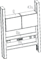
FIG. 8 is a schematic top view of the lift cabinet system of FIG. 3;
FIG. 9 is a schematic cross-sectional view taken along line B-B of FIG. 8;
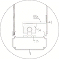
fig. 10 is a schematic view of another connection between the guide rail, the slide and the first vertical connection 4.
Detailed Description
The following describes the structure of the elevator platform cabinet system applying the technical scheme of the invention with reference to the accompanying drawings.
As shown in fig. 1, 2 and 3, the lifting platform cabinet includes a table 9 with a bottom, two right and left combined side columns which are vertically arranged relatively, namely a first combined side column 100, a second combined side column 100a, and storage cabinets (8, 8a, 8 b) arranged in the inner space between the two combined side columns. The first combined side column 100 and the second combined side column 100a are respectively fixed beside the bottom table 9, and when the storage cabinet (8, 8a or 8 b) descends, the storage cabinet is positioned beside the bottom table 9. Of course, in other embodiments, the first and second side posts 100 and 100a may be fixed on the bottom table 9, and the storage cabinets (8, 8a, 8 b) may be located above the bottom table 9. In this way, the first and second side posts 100 and 100a can be stably positioned by the bottom table 9.
As shown in fig. 4 and 5, the first combination side post 100 includes a side post, an outer side fascia 3 inserted into the side post, and a lifting mechanism. The lifting mechanism comprises a driver 61 and a telescopic rod 6 which is driven by the driver 61 to do telescopic motion along the vertical direction. The side columns comprise a front column 1 and a rear column 1a which are correspondingly arranged front and back, and the front column 1 and the rear column 1a are respectively in a hollow section shape. The front pillar 1 and the rear pillar 1a have the same cross-sectional shape when viewed in cross section, and respectively include closed hollow cavities (15, 15 a) defined by side walls, but may also define semi-closed hollow cavities in other embodiments. In this way, the front pillar 1 and the rear pillar 1a are three-dimensional members having a bent structure, and the structural strength and the support strength of the front pillar 1 and the rear pillar 1a are reinforced by the bent structure. Outer slots (11, 11 a) with opposite notches are respectively arranged at positions close to the outer sides of the front column 1 and the rear column 1a, two sides of the outer decorative plate 3 are respectively inserted into the outer slot 11 of the front column 1 and the outer slot 11a of the rear column 1a, the outer decorative plate 3 seals an outer open part of a space between the front column 1 and the rear column 1a, so that the front column 1, the rear column 1a and the outer decorative plate 3 form a first accommodating space 10, and the first accommodating space 10 is provided with a first inner open part 101 facing to the inner direction. The first accommodating space 10 accommodates a first telescopic rod 6 which is a telescopic rod capable of vertically extending and retracting. The automobile rear pillar structure further comprises an inner side trim 31, inner side slots (12, 12 a) with opposite notches are respectively arranged on the positions close to the inner sides of the front pillar 1 and the rear pillar 1a, two sides of the inner side trim 31 are respectively inserted into the inner side slots 12 of the front pillar 1 and the inner side slots 12a of the rear pillar 1a, and the inner side trim 31 is connected to an upper connecting block 17 to be discussed below through a connecting piece (not shown). The inner side trim 31 closes only the upper portion of the inner side opening of the accommodating space 10, but may close only the lower portion of the inner side opening of the accommodating space 10 in other embodiments. In the cross section, at least 2 axial grooves (16, 16 a) for connecting screws are respectively arranged on the front column 1 and the rear column 1a, and of course, in other embodiments, the axial grooves can also be axial holes. And an upper joint block 17 and a lower joint block 18, the upper joint block 17 being fastened to the top end faces of the front and rear pillars 1, 1a by being screwed to the axial grooves (16, 16 a), and the lower joint block 18 being fastened to the bottom end faces of the front and rear pillars 1, 1a by being screwed to the axial holes (16, 16 a). Thus, the upper connecting block 17 and the lower connecting block 18 can not only respectively block the top end and the bottom end of the front column 1 and the rear column 1a, but also strengthen the connecting strength among the front column 1, the rear column 1a, the outer side decorative plate 3 and the inner side decorative plate 31, so that the front pillar 1, the rear pillar 1a, and the outer and inner quarter panels 3 and 31 are combined into a main pillar having a stable coupling structure and structural strength, and thus, when the first combined side column 100 is applied to the counter and the storage cabinet of the counter is driven to move vertically by the telescopic rod 6, the main column can be selected to provide stable and effective guide for the collection cabinet, the shaking of the collection cabinet is reduced, the movement stability of the collection cabinet is improved, in this embodiment, however, the cabinet is provided with vertical movement guidance mainly by means of guide rails and sliders as will be discussed below. The second combination side post 100a also includes a side post, a lifting mechanism, an inner trim panel, an outer trim panel, an upper connection block, and a lower connection block, and the connection relationship, function, and technical effects between them are the same as those of the first combination side post 100, and a discussion thereof will not be repeated.
A first vertical connecting portion 4 is further disposed at the first combined side column 100, the first vertical connecting portion 4 extends vertically for a certain length, and the first vertical connecting portion 4 is dragged by the first telescopic rod 6 to be capable of moving vertically relative to the first combined side column 100. Specifically, the first vertical connecting portion 4 has a plate shape and includes a plate main body 40 and first guide edges (41, 42) facing the first combination side post 100. The plate body 40 is covered on the first inner side open part 101, and the plate body 40 can totally or partially close the first inner side open part 101 along with the up-down movement of the plate body 40. The inner side walls of the front column 1 and the rear column 1a of the first combined side column 100 are respectively provided with a first inner side guide groove (14, 14 a) matched with the first guide edge (41, 42), the notch of the first inner side guide groove (14, 14 a) faces to the inner side direction and is arranged along the vertical extension direction, the first guide edge (41, 42) is inserted into the first inner side guide groove (14, 14 a), and when the first vertical connecting part 4 vertically moves, the first guide edge (41, 42) vertically moves along the first inner side guide groove (14, 14 a). The first vertical connecting portion 4 serves as an inner side plate of the first combination side post 100 and shields internal functional members such as the first telescopic rod 6 and the like stored in the first storage space 10. Of course, in other embodiments, it is also possible that the first vertical connecting portion 4 may take other forms, such as a rod shape, and be arranged inside or outside the first accommodating space 10. The first vertical connecting portion 4 extends vertically for a certain length, so that a connecting area which extends vertically and has a proper area is formed on the first vertical connecting portion 4, and a technical foundation is provided for connecting a plurality of storage cabinets in a vertical manner. A second vertical connecting portion 4a is further disposed at the second combined side column 100a, and the second vertical connecting portion 4a has the same structure, function and technical effect as the first vertical connecting portion 4, and will not be discussed again here. In addition, a first bending edge 43 facing the storage cabinet 8 is provided on the plate body 40 of the first vertical connecting portion 4, a second bending edge 43a facing the storage cabinet 8 is provided on the plate body of the second vertical connecting portion 4a, and the first bending edge 43 and the second bending edge 43a are connected to the storage cabinet 8, respectively.
As shown in fig. 7, a first guide rail 51 and a vertical rod 52 extending in the vertical direction are further provided in the first accommodating space 10, the first guide rail 51 is connected to the vertical rod 52 by a screw 54, the top end of the vertical rod 52 is connected to the upper connecting block 17, and the bottom end of the vertical rod 52 is connected to the lower connecting block 18. The sliding device further comprises a first sliding block 5 which is positioned on the first guide rail 51 in a sliding mode, and the first guide rail 51 is connected with the first sliding block 5 in a sliding mode through a dovetail groove structure, so that the sliding stability of the first sliding block 5 is improved. The first sliding block 5 is fixedly connected to the plate main body 40 of the first vertical connecting portion 4 through a screw 53, so that the first vertical connecting portion 4 is also slidably positioned on the first guide rail 51 through the first sliding block 5, so that the first vertical connecting portion 4 can move vertically under the guidance of the first guide rail 51. The first vertical connecting portion 4 can be vertically moved smoothly by the sliding fit relationship of the first slider 5 and the first guide rail 51. In addition, when the first vertical connecting part 4 has a relatively long vertical extension length, the number of the first sliding blocks 5 can be increased appropriately, the shape of the first vertical connecting part 4 can be corrected by the transverse shape correction function of the first sliding blocks 5, and the bulging deformation of the first vertical connecting part 4 after being subjected to the gravity of foreign objects such as the storage cabinets (8, 8 a) can be reduced. In addition, another connection mode can be adopted among the first guide rail 51, the first slider 5 and the first vertical connecting portion 4, as shown in fig. 10, the first guide rail 51a is fixedly arranged on the front pillar 1, the first slider 5a is slidably positioned on the first guide rail 51a, the front pillar further comprises an L-shaped corner brace 55a, one arm of the L-shaped corner brace 55a is fixedly connected to the first slider 5a, and the other arm of the L-shaped corner brace 55a is fixedly connected to the plate main body 40 of the first vertical connecting portion 4. The second combined side column 100a is also provided with a vertical rod, a second slider, a second guide rail, and a second vertical connecting portion 4a, and the connection relationship and the layout relationship between the vertical rod, the second slider, the second guide rail, and the second vertical connecting portion 4a are the same as above, and are not described herein again. In other embodiments, the storage cabinet may also be connected to the first and second sliders 5 and 5a so that the storage cabinet can be vertically moved under the guidance of the first and second rails 51 and 51 a.
As shown in fig. 6, a first inner open portion 101 of the first combined side column 100 and a second inner open portion of the second combined side column 100a are oppositely disposed, a transverse connecting portion 7 is disposed in an inner space between the first combined side column 100 and the second combined side column 100a, a left end of the transverse connecting portion 7 is connected to a top end portion of the first telescopic rod 6 by a space reserved in the first inner open portion 101, and a right end of the transverse connecting portion 7 is connected to a top end portion of a second telescopic rod, which is a telescopic rod accommodated in the second accommodating space 10, by a space reserved in the second inner open portion. Specifically, a first window 401 is arranged on the plate main body 40 of the first vertical connecting portion 4, a second window is arranged on the plate main body of the second vertical connecting portion 4a, the left end of the transverse connecting portion 7 penetrates through the first window 401 to be directly connected with the top end portion of the first telescopic rod 6, and the right end of the transverse connecting portion 7 penetrates through the second window to be directly connected with the top end portion of the second telescopic rod. Of course, in other embodiments, the left end of the transverse connecting portion 7 and the top end portion of the first telescopic rod 6 may be connected together through a transition connector, the transition connector passes through the first window 401, and the left end of the transverse connecting portion 7 does not pass through the first window 401. The right end of the transverse connecting portion 7 is connected with the top end portion of the second telescopic rod through a transition connector, the transition connector penetrates through the second window, and the right end of the transverse connecting portion 7 does not penetrate through the first window 401. To sum up, the left and right ends of the transverse connecting part 7 are respectively connected to the top ends of the first telescopic rod 6 and the second telescopic rod. When the first telescopic rod 6 and the second telescopic rod vertically extend and retract, the transverse connecting portion 7 can be driven to vertically move. The transverse connecting part 7 becomes a first power output end of the first telescopic rod 6 and the second telescopic rod. In addition, the relative positions of the first telescopic rod 6 and the second telescopic rod in the transverse direction can be solidified through the connection between the transverse connecting part 7 and the first telescopic rod 6 and the second telescopic rod, so that a technical basis can be provided for further solidifying the relative positions of the first combined side column 100 and the second combined side column 100a in the transverse direction. Meanwhile, when the transverse connecting portion 7 vertically moves, the first vertical connecting portion 4 is dragged to vertically move relative to the first combined side column 100, and the second vertical connecting portion 4a is dragged to vertically move relative to the second combined side column 100 a. Of course, in other embodiments, the first vertical connection 4 may be directly connected to the first telescopic rod 6, and the second vertical connection 4a may be directly connected to the second telescopic rod. The first vertical connecting portion 4 and the second vertical connecting portion 4a become the second power output ends of the first telescopic rod 6 and the second telescopic rod.
A first collection cabinet 8, a second collection cabinet 8a and a third collection cabinet 8b are further arranged between the first vertical connecting portion 4 and the second vertical connecting portion 4 a. The first storage cabinet 8 is a cabinet body having a closed storage space, the second storage cabinet 8a is a plate-shaped single-layer shelf (or a plate-shaped multi-layer shelf), and the first storage cabinet 8 and the second storage cabinet 8a are respectively connected to the first vertical connecting portion 4 and the second vertical connecting portion 4a and are connected to the first telescopic rod 6 and the second telescopic rod through the first vertical connecting portion 4 and the second vertical connecting portion 4 a. The third storage cabinet 8 is connected to the first vertical connecting portion 4 and the second vertical connecting portion 4a, the transverse connecting portion 7, and the first telescopic rod 6 and the second telescopic rod through the transverse connecting portion 7. When the first telescopic rod 6 and the second telescopic rod synchronously and vertically extend and retract, the first vertical connecting part 4, the second vertical connecting part 4a and the storage cabinets (8, 8a, 8 b) can be driven to vertically move. Wherein, the transverse connecting part 7 and the third storing cabinet 8b are a part which is combined into a whole. Specifically, the third storage container 8b is in a square column shape, the transverse connecting portion 7 and the power unit 61 are stored therein, and a top wall of the third storage container 8b is a storage layer of the third storage container 8 b. A first driver (not shown in the figure) is further arranged in the first combined side column 100 and drives the first telescopic rod 6 to vertically extend and retract, and a second driver (not shown in the figure) is further arranged in the second combined side column 100a and drives the second telescopic rod to vertically extend and retract; two shaft extension ends of the power device 61 are respectively in transmission connection with the first driver and the second driver, and then respectively drive the first telescopic rod 6 and the second telescopic rod to realize synchronous lifting action. In this way, it is advantageous to control the first vertical connecting portion 4 and the second vertical connecting portion 4a to be kept in a substantially horizontal arrangement during or after the vertical movement, and the transverse connecting portion 7 and the storage cabinets (8, 8a, 8 b) to be kept in a substantially horizontal arrangement during or after the vertical movement. In other embodiments, it is also possible that the transverse connecting portion 7 and the third storage compartment 8b are separated, and the power device 61 may be selectively disposed on the transverse connecting portion 7 or the third storage compartment 8 b.
Claims (12)
1. The lifting platform cabinet system is characterized by comprising two combined side columns which are vertically arranged on the left and right oppositely, namely a first combined side column and a second combined side column, wherein a first accommodating space is arranged in the first combined side column, the first accommodating space is provided with a first inner side opening part facing to the inner side direction, a first telescopic rod capable of vertically stretching and moving is accommodated in the first accommodating space, a second accommodating space is arranged in the second combined side column, the second accommodating space is provided with a second inner side opening part facing to the inner side direction, and a second telescopic rod capable of vertically stretching and moving is accommodated in the second accommodating space; a storage cabinet is arranged in an inner space between the first combined side column and the second combined side column, and the storage cabinet is connected to the first telescopic rod and the second telescopic rod and can drive the storage cabinet to vertically move in the inner space defined between the first combined side column and the second combined side column when the first telescopic rod and the second telescopic rod synchronously vertically extend and retract.
2. The lift table cabinet system according to claim 1, wherein a first vertical connecting portion is further disposed at the first combined side column, the first vertical connecting portion extends a certain length in a vertical direction and is dragged by the first telescopic rod to be vertically movable with respect to the first combined side column, a second vertical connecting portion is further disposed at the second combined side column, the second vertical connecting portion extends a certain length in a vertical direction and is dragged by the second telescopic rod to be vertically movable with respect to the second combined side column, and the stowage bin connects the first vertical connecting portion and the second vertical connecting portion and is connected to the first telescopic rod and the second telescopic rod through the first vertical connecting portion and the second vertical connecting portion.
3. The lift table cabinet system of claim 2, wherein the first vertical connection is plate-like and covers the first interior open area and the second vertical connection is plate-like and covers the second interior open area.
4. The lift table cabinet system according to claim 3, wherein the first vertical connecting portion has a first guide edge facing the first combined side post, and the inner side wall of the first combined side post has a first inner guide groove adapted to the first guide edge, the first inner guide groove extending vertically, the first guide edge being inserted into the first inner guide groove, and the first guide edge moving vertically along the first inner guide groove when the first vertical connecting portion moves vertically; the second vertical connecting portion is provided with a second guide edge facing the second combined edge column, a second inner side guide groove matched with the second guide edge is formed in the inner side wall of the second combined edge column, the second inner side guide groove is arranged along the vertical extension, the second guide edge is inserted into the second inner side guide groove, and when the second vertical connecting portion vertically moves, the second guide edge vertically moves along the second inner side guide groove.
5. The lift table cabinet system of claim 2, wherein a first bent edge is provided on the first vertical connecting portion toward the stowage bin, a second bent edge is provided on the second vertical connecting portion toward the stowage bin, and the first and second bent edges are respectively connected to the stowage bin.
6. The lift table cabinet system of claim 1, further comprising a transverse connection, a left end of the transverse connection being connected to the first telescoping rod, and a right end of the transverse connection being connected to the second telescoping rod; therefore, when the first telescopic rod and the second telescopic rod synchronously and vertically extend and retract, the transverse connecting part can be driven to vertically move; the storage cabinet is connected with the transverse connecting part and is connected with the first telescopic rod and the second telescopic rod through the transverse connecting part.
7. The lift platform cabinet system according to claim 6, wherein a first actuator is further disposed in the first combined side column and drives the first telescopic rod to move vertically, and a second actuator is further disposed in the second combined side column and drives the second telescopic rod to move vertically; the transverse connecting part or the storage cabinet is provided with a power device, and two shaft extending ends of the power device are respectively in transmission connection with the first driver and the second driver so as to respectively drive the first telescopic rod and the second telescopic rod to realize synchronous lifting action.
8. The lift table cabinet system according to claim 1, wherein a first guide rail extending vertically and a first slider slidably positioned on the first guide rail are further provided in the first accommodating space, a second guide rail extending vertically and a second slider slidably positioned on the second guide rail are further provided in the second accommodating space, and the storage cabinet is further connected to the first slider and the second slider so as to allow the storage cabinet to move vertically under the guidance of the first guide rail and the second guide rail.
9. The lift table cabinet system according to claim 2, wherein a first guide rail extending vertically, a first slider slidably positioned on the first guide rail, and a first vertical connecting portion further connected to the first slider so as to allow the first vertical connecting portion to move vertically under the guidance of the first guide rail are further provided in the first accommodating space; and a second guide rail extending vertically and a second sliding block positioned on the second guide rail in a sliding manner are further arranged in the second accommodating space, and the second vertical connecting part is further connected to the second sliding block so as to enable the second vertical connecting part to vertically move under the guidance of the second guide rail.
10. The lift table cabinet system according to any one of claims 1 to 9, further comprising a bottom table, wherein the first and second side pillars are fixed to the bottom table, respectively, and the stowage housing is located above the bottom table.
11. The lift table cabinet system of any one of claims 1 to 9, further comprising a bottom table, said first and second modular side posts being secured to respective sides of said bottom table, said first and second modular side posts being positioned to the sides of said bottom table when said stowage bin is lowered.
12. The lift table cabinet system of any one of claims 1 to 9, wherein the cabinets comprise a first cabinet and a second cabinet, the second cabinet being a single-layer shelf in the form of a plate, and the first cabinet being a multi-layer shelf in the form of a plate.
Priority Applications (1)
| Application Number | Priority Date | Filing Date | Title |
|---|---|---|---|
| CN201911207250.1A CN112871237A (en) | 2019-11-29 | 2019-11-29 | Lifting table cabinet system |
Applications Claiming Priority (1)
| Application Number | Priority Date | Filing Date | Title |
|---|---|---|---|
| CN201911207250.1A CN112871237A (en) | 2019-11-29 | 2019-11-29 | Lifting table cabinet system |
Publications (1)
| Publication Number | Publication Date |
|---|---|
| CN112871237A true CN112871237A (en) | 2021-06-01 |
Family
ID=76039178
Family Applications (1)
| Application Number | Title | Priority Date | Filing Date |
|---|---|---|---|
| CN201911207250.1A Pending CN112871237A (en) | 2019-11-29 | 2019-11-29 | Lifting table cabinet system |
Country Status (1)
| Country | Link |
|---|---|
| CN (1) | CN112871237A (en) |
Citations (6)
| Publication number | Priority date | Publication date | Assignee | Title |
|---|---|---|---|---|
| DE10319941A1 (en) * | 2003-05-02 | 2004-11-18 | Volkswagen Ag | Telescopic table pillar for table, especially in motor vehicle, has inner part consisting of fixed inner part, relatively movable locking pillar additionally joined to table board or holding part |
| CN106455807A (en) * | 2014-05-26 | 2017-02-22 | 利纳克有限公司 | Supporting frame for a piece of furniture |
| CN107234118A (en) * | 2017-07-28 | 2017-10-10 | 广东天赐湾实验室装备制造有限公司 | Vent cabinet with lifting sash |
| CN208687252U (en) * | 2018-07-25 | 2019-04-02 | 泰州市创新电子有限公司 | A thin lift bracket |
| CN109984478A (en) * | 2019-04-04 | 2019-07-09 | 温州医科大学 | File cabinet is used in a kind of management of insane asylum |
| CN211677854U (en) * | 2019-11-29 | 2020-10-16 | 广东天赐湾实验室装备制造有限公司 | Lifting table cabinet system |
-
2019
- 2019-11-29 CN CN201911207250.1A patent/CN112871237A/en active Pending
Patent Citations (6)
| Publication number | Priority date | Publication date | Assignee | Title |
|---|---|---|---|---|
| DE10319941A1 (en) * | 2003-05-02 | 2004-11-18 | Volkswagen Ag | Telescopic table pillar for table, especially in motor vehicle, has inner part consisting of fixed inner part, relatively movable locking pillar additionally joined to table board or holding part |
| CN106455807A (en) * | 2014-05-26 | 2017-02-22 | 利纳克有限公司 | Supporting frame for a piece of furniture |
| CN107234118A (en) * | 2017-07-28 | 2017-10-10 | 广东天赐湾实验室装备制造有限公司 | Vent cabinet with lifting sash |
| CN208687252U (en) * | 2018-07-25 | 2019-04-02 | 泰州市创新电子有限公司 | A thin lift bracket |
| CN109984478A (en) * | 2019-04-04 | 2019-07-09 | 温州医科大学 | File cabinet is used in a kind of management of insane asylum |
| CN211677854U (en) * | 2019-11-29 | 2020-10-16 | 广东天赐湾实验室装备制造有限公司 | Lifting table cabinet system |
Similar Documents
| Publication | Publication Date | Title |
|---|---|---|
| CN108883719B (en) | Caravan | |
| CN202108407U (en) | Cable wiring structure of telescopic translational door | |
| CA2412086A1 (en) | Cargo shield | |
| US20040222723A1 (en) | Pull-out guide fitting for drawers | |
| US9919414B1 (en) | Tool cabinet | |
| US9815189B1 (en) | Tool cabinet | |
| CN211677854U (en) | Lifting table cabinet system | |
| CN113120008A (en) | Driver platform and have its rail vehicle | |
| CN212382268U (en) | Combined side column for lifting mechanism and applied table cabinet | |
| CN108756561A (en) | The furniture part of sliding for multi-part door and furniture with the furniture part | |
| CN112871237A (en) | Lifting table cabinet system | |
| US10988085B2 (en) | Motor vehicle | |
| CN112869347A (en) | Combined side column for lifting mechanism and applied table cabinet | |
| CN104859549B (en) | Mark time mechanism and the movable step device for automobile inspection | |
| CN206663187U (en) | Tool cabinet with lift table | |
| WO2024078940A1 (en) | Item of furniture | |
| CN114212741A (en) | Building materials adsorption equipment convenient to operation | |
| EP3515794B1 (en) | Cabin for industrial vehicle comprising an extractable side ladder to allow access to said cabin | |
| DE102016123834B4 (en) | Building structure and vehicle with a building structure | |
| CN220948233U (en) | Lifting square cabin suitable for vehicle | |
| CN216508046U (en) | Folding table plate for commercial vehicle | |
| KR101358262B1 (en) | Horizontal Folding type Sunroof Apparatus | |
| CN215718176U (en) | Door opener with supporting rod | |
| CN223533313U (en) | Rear tailgate opening and closing structure assembly and vehicle | |
| CN217804282U (en) | Carriage assembly and vehicle |
Legal Events
| Date | Code | Title | Description |
|---|---|---|---|
| PB01 | Publication | ||
| PB01 | Publication | ||
| SE01 | Entry into force of request for substantive examination | ||
| SE01 | Entry into force of request for substantive examination |